Zubler Z1-M User manual

Z1- M
www.zubler.de
EN 09-2019
Single suction systems

2
0. User information page 4
0.1 Declaration of conformity
0.2 Intended purpose of use
0.3 Technical requirements
1.
Installation of the appliance
page 6
1.1 Scope of supply and accessories
1.2
Installation of the extraction system
1.2.1 Suction line
1.2.2 Exhaust
1.2.3 exhaust air to the outside
1.2.4 Setting up Z1-M (with handle)
1.2.5 Z1-M (with suspension)
1.2.6 Mains connection
1.3 Connection of working tools
1.3.1
Appliances without interface
1.3.2 Appliances with switching output
(Potential free e.g. Relais)
1.3.3 Appliances with switching
output
230V socket
1.4 Intake system
2.
Functional description
page 12
2.1 Control unit
2.2 Commissioning
2.3 Automatic operation
2.4
Selecting and saving suction levels
2.5 Current suction power
2.6 Setting the suction overrun time
2.7
Fine tuning of the automatic operation
2.8
Switching the extraction system off
Content

3
3. Warranty terms page 18
3.1 Filter bag
3.2Main filter
3.3 Motor
3.3.1 Motor replacement
3.3.2 Carbon brush replacement
3.3.3 Reset carbon brush time
3.4 Spare parts
3.5 Technical structure
4. Status Messages page 23
5. Technical Data page 25
6. Warranty
page 26
7.
Disposal instructions
page 27
Advanced settings are provided by the Zubler Sucti-
on-Technology APP , which is available for Android
tablets or phones.
Therefore follow the users manual of the Zubler Suc-
tion-Technology APP, which is downloadable from
www.zubler.de.

4
0.
We, Zubler Gerätebau GmbH
Buchbrunnenweg 26
89081 Ulm Jungingen
declare, that the product vacuuming unit
Z1 - M
conforms to the health and safety
requirements set out in the directives
2014/30/EC EMV-Directive
2014/35/EC Low-Voltage Directive
2006/42/EC Machines Directive
Any modification not specifically approved
by us voids the validity of this declaration.
Kurt Zubler
ceo
0.1 Declaration of conformity
Introduction
Dear customer,
we are pleased, that you have decided for a Zubler extraction system and
hope it will enhance your work. The continuous development of our tech-
nology is based on the co-operation with experienced
dental technicians. The focus lies on the aim to optimize the extraction
technology in the fields of performance, noise and reliability.
Please read this operating manual carefully in order to ensure a prob-
lem-free operation.

5
0.2 Intended purpose of use
0.3 Operating Environment
Temperature: +5°C bis +40°C
Max. permissible relative humidity: max. 80% (bei 30°C)
Total connected load : 10A
This extraction system is designed exclusively for dry dusts!
Its use for the extraction of other types of dust or gases must be clarified
with the manufacturer before putting into operation.
Work must be stopped immediately and the system switched off in the
event of the appearance of visible clouds of dust or noticeably insufficient
suction power.
Inform your dealer or our service team.
The Z1 is designed for indoor use.
The volume of air circulated by the system and returned to the room may
not exceed 50% of the room air volume in closed rooms.
Use is restricted to persons who have been trained in its handling and are
authorised to do so. We reserve the right to make changes even without
updating this manual.

6
1.
0,34kg
Item Number
Adaptor C14 / CEE
012-00701
H14-Filter H-Typ 556-0052
Activated carbon filter C-Typ
556-0051
exhaust adapter RD72 /DN75
896-1103
diffusor-holder (without filter)
556-0057
Installation of the appliance
1.1 Scope of supply and accessories
1x Z1 - M suction unit mobile
1x Power cable
1x
cable C13/C14 (ECOonly)
1.8m hose 38 mm
1x elbow adaptor 50/40 mm
Special Accessories

7
10
1
3
2
16
10
1.2.1 Suction line
nProvide a sufficiently stable and
leveled surface. Ensure that the
housing does not touch the furniture
to avoid noise production by
resonances.
nPlug in the muffle of the enclosed
suction hose to the intake nozzle (2)
and the other side firmly to your intake
system.
1.2 Installation of the Z1 - M
1 Closure
2 Exhaust connection
3 Filter door
16 Diffusor
30
Exhaust Adaptor
1.2.2 Exhaust
nIf using the unit in non-stop operation,
the exhausting air temperature is
increased.
nTo avoid overheating, the exhausting
air must be able to flow out and
spread free.
nAlternatively it is recommended to
giude the exhaust air to the outside.
1.2.3 exhaust air to the outside
nBy turning counterclockwise, the
exhaust cover 16 and the exhaust air
fleece can be removed.
nA hose DN50 or a rigid HT pipe DN50
can be attached to the nozzle and the
exhaust air directed to the outside.
Fig. 1
Fig. 2

8
21
23
22
1.2.4 Setting up Z1-M (with handle)
nPlace the exhaust system on a flat,
smooth surface in an easily accessible
location near the intake system.
1.2.5 Z1-M (with suspension)
nAttach the hanging plate 21 in an
easily accessible place near the
aspiration system with 6x SPAX
5x20mm or M5.
nFor attaching the Z1-M, 400mm are
needed forwards and downwards, for
the suction hose to the rear 200mm.
nPush the suction unit with the
suspension 22 into the hanging plate
21. Fix the suction unit with the two
knurled screws 23.
Installation in the furniture
When installing in cabinets or narrow
niches, the following points must be
observed:
nThe extraction system must be able to
suck in cool air from the front. (Fig.4)
nWarm exhaust air that is blown out
to the rear must not come forward.
For this purpose, it is necessary that
all around the suction provided a
close-fitting partition to the rear, or,
as described in 1.2.2 and 1.2.3, the
exhaust air is passed away.
Fig. 4
Fig. 6
Cooling air

9
77
48
6
ZUBLER Gerätebau GmbH
Buchbrunnenweg 26
D-89081 Ulm
Tel. +49(0)731 1452-0 / www.zubler.de
Suction unit
Z1-M
Spannung 230V
Gesamtleistung max. 2000W
Absaugung max. 700W
Automatiksteckdose 1200W
Z1 ECO 00-11111-22
Made in
Germany
1.2.6 Mains connection
nBefore connecting the unit to the
mains power supply, check if the
voltage given on the number plate
(Fig.6) corresponds with the local
voltage.
nPlug the enclosed power cord into the
IEC C14 connector 6 and the mains
plug into a local power socket.
nThe suction unit must not be switched
ON/OFF with the mains power supply.
The mains power supply must be
connected permanently.
4 Data interface
6
Mains power supply (IEC C14)
7 Main fuse (10A)
7 Fuse power socket (6A)
8
Autom. power socket (IEC F)
9 24V interface
Fig. 7:
Fig. 8:
Connectors

10
3
2 4
1 5
6
1.3.1
Appliances without interface
n
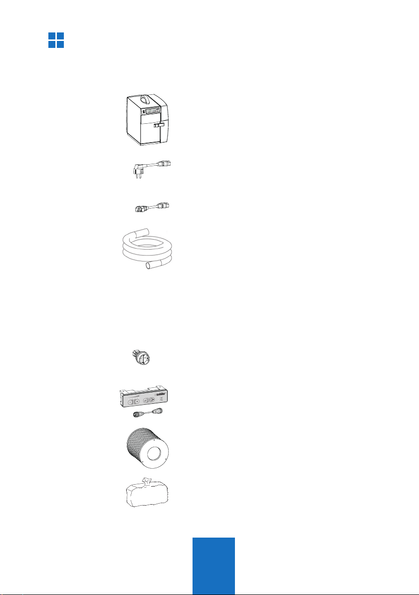
If your appliance is equipped with a IEC
plug type C14, use the enclosed IEC
power cord (C13/C14) to connect the
appliance to power socket 8.
The power cord which was enclosed
with your appliance is not needed.
n
If your appliance is equipped with a CEE
mains plug type F or C, you will need an
optional CEE-adaptor (CEE/C14) O.No.
012/00701.
The max. power rate of the appli-
ance is limited to 600W (120V)or
1200W (240V)!
1.3.2 Appliances with switching output
nIf your working appliance has a
switching output, a control cable
(special accessory) can be used to
connect to the extraction system.
Instead of C13 low temperature power
outlet 8, use the data interface 4.
nSome handpiece controls, e.g. The
Zubler K50, Kavo K-Control or Schick
Qube can also be coupled with the
suction point opener via a control
line instead of the power supply.
(Matching adapter cable on request).
1.3.3
Appliances and machines with
230V output
nIf there is a 230 V outlet on the
machine for the extraction, use
exclusively the SL230 accessory
adaptor
1.3 Connecting the working tools
Pin Cabel
assignment plan
1 grey Start 2 (IN)
2 (pink) NC
3 white
Freigabe (OUT)
4 brown GND
5 green Start (IN)
6 yellow GND
PIN assignment Connector 15

11
C
B
A
/
R1200
Basic system requirements include
optimal particle flow, minimal noise
production and ergonomic posture
promotion.
The following criteria promote these basic
requirements and are specifically adapted
to Zubler suction systems.
nSuction funnel R1200,
nRectangular pipe R1000, R1300
nRectangular silencer R1100
nThe R1200 suction funnel (21) was
tested according to GS-IFA-M20 test
no. 1305026 for a minimum suction
performance of 20 l/s.
nSitting in the upright position in a
posture preserving ergonomically
designed chair.
nWorkpiece as close as possible to
the suction funnel 21; no dust cloud
may be visible. Trails of dust must be
drawn into the hopper.
nDirection of viewing of the workpiece
perpendicular to the protective screen.
1.4 Intake system
A Suction funnel R1200
B
Rectangular pipe R1300
C Rectangular pipe R1000
Fig. 12

12
T1 T2 T3 T4
L6
L4
L5
29
L2
L3L1
2.
L1 LED Power level display
L2 LED Bluetoothanzeige
L3 LED “ON”
L4 LED Filter
L5 LED Service
L6 LED “OFF”
T1 minus-button
T2 plus-button
T3 Enter-button
T4 ON / OFF - button
29 Main switch
nThe extraction system must be
installed and connected as described
in section 1.
nSwitch on the main switch 29.
nOne ore more LEDs of the suction
level L1 are flashing.
After approx. 5s the suction unit is
ready and the last saved suction level
is displayed. (At setup level 1).
nBy pressing the ON/OFF button T4 the
suction is started with the selected
suction level L1.
nIf changeing the suction level for the
first time, the unit will take some time
to calibrate the suction volume and
compensate the flow resistances.
nFor setting and saving suction levels,
see section 2.4.
Functions
Fig. 13
2.1 Control unit
2.2 Commissioning

13
-+
T1 T2
If a dust producing appliance is connected
to the extraction system, the sensitivity
must be adjusted for an automatic start of
the extractor.
The following steps are necessary in
order to teach the appliance:
nThe appliance (max. 6A, 120V:600W,
240V:1200W) must be connected to
the socket of the extraction system.
nPreselect the handpiece speed at
which the extraction system should be
started.
nStart the appliance or the handpiece
nd keep it running.
nWhile the appliance is running, press
and hold the buttons T1 (minus) and
T2 (plus) at the same time for at
least 3 seconds until a signal sounds
and the LEDs of the display L1 light
up. The extraction system will start
running for approx. 3 seconds.
nStill keep the appliance running.
nAs soon as another signal sounds
and the LEDs of the display L1 start
flashing, switch off the appliance or
stop the handpiece immediately.
nWait until a final signal sounds and
the LEDs of the display L1 show the
preselected suction level again.
2.3 Setting up automatic operation:

14
T1 T2
-+
T3
n
The suction levels 1 – 5 can be selected
with the T1 (minus) and T2 (plus) buttons.
nThe suction level shown on the display
L1 is the currently saved level with which
the extraction system switches on.
2.4 Selecting and saving suction levels
nPress the Enter button T3 to save the
new suction level
nIf the suction level is changed
without pressing the Enter button
T3, the extraction system will run the
lastsaved suction level the next time
the unit is started.
n
Suction level 5 (“Turbo mode”) is only
avail. for short time usage (factory set to
5 min.) and can therefore not be saved
in regulation mode.
n
While in “Turbo mode” the LED for
suction level 5 is flashing.
Once the time is elapsed, the suction
will fall back to the saved suction level
1-4.
n
Further adjustments can be made with
the Zubler Suction-Technology APP
(Android only).
Level Z1-M
1 20 l/s
2 25 l/s
3 30 l/s
4 35 l/s
5(„turbo“) max 40 l/s

15
If the LEDs of display L1 light up
according to the selected suction level
during suction operation, this means that
the preset air flow rate of the suction
level is also actually being provided
and the motor has not yet reached its
maximum power.
If the desired air flow rate cannot be
attained (due to flow resistance or
filter clogging), then LED lights that are
solidsignify the attainable setting, while
the flashing LEDs signify the setting
and corresponding suction loss. The
volumetric flow control device is preset
in the factory so that a warning signal
sounds and the Filter Maintenance LED
L4 lights up only at minimum suction
power.
In the advanced settings (see section 3)
it is possible to set this so that the filter
warning is given as soon as the suction
power decreases to the next lower
suction level.
nFurther adjustments can be made with
the Zubler Suction-Technology APP.
2.5 Current suction power
Example:
Suction level 3 is selected, but
the air flow rate
corresponds only
to level 2.

16
T1
-
T2
+
T3 T2
T1
-
npress and hold the plus button T2
for at least 3 seconds until only the
middle LED of display L1 is lit
nthe suction time can be reduced by 1
sec per LED jump to the left with the
T1 (-) button or increased by 1 sec per
LED jump to the right with the T2 (+)
button.
npress the Enter button T3 to save the
new value
npress the fan button T4 to abort the
procedure without saving
nthe suction overrun time can be
prolonged by a further 2 sec by
repeating the procedure.
n
Further adjustments can be made with
the Zubler Suction-Technology APP
(Android only).
2.6 Setting the suction cutoff time
For the extraction of the residual dust in the air, it is possible to extend the
time the extraction system should continue to run during breaks or after the
end of dust production. The factory setting is 3 seconds.
npress and hold the minus button T1
for at least 3 seconds until only the
middle LED of display L1 is lit
nlower the switch-on threshold with the
T1 (-) button (extraction starts earlier
neasier; this is a solution if the
extraction system switches off or
doesn’t start-up immediately despite
dust being produced)
2.7 Fine tuning of the automatic operation (ECO only)
If the automatic sensitivity matching of the dust producer to the extraction
system has not yet led to an ideal result after section 1, the switch-on
threshold of the extraction can still be manually readjusted.

17
T2
+
T3 T2
nthe switch-on sensitivity of the T2
(+) button (extraction starts later /
less easily; this is a solution if the
extraction system occasionally starts
up on its own or already runs in
standby).
npress the Enter button T3 to save the
new value
npress the fan button T4 to abort the
procedure without saving
nthe switching sensitivity can be set
even higher or lower by repeating the
procedure.
nsee section 3 for advanced settings
and troubleshooting.
The Z1 extraction system is intended only
for switched-on standby operation.
If the extraction system is switched off
or disconnected from the power supply, a
switch-off time of at least 10 seconds is
necessary.
If the extraction system is inadvertently
switched back on immediately, or in the
case of a short-term power failure of less
than 10 seconds, the system can enter
the error state. LED L5 lights up. In this
case the extraction system must remain
switched off for longer than 2 minutes in
order to be able to start it again.
Note! The Z1 extraction system cannot
be switched on and off by external
switching electronics that interrupt the
power supply to the extraction system.
2.8. Switching the extraction system off

18
3.
u
v
w
y
1
x
9
3
3
Removal of the filter basket
nswitch the system off at the main
switch 29 (fig. 9) and also switch
your working appliance off at the
associated main switch to prevent
inadvertent start-up.
uopen closure 1 by lifting it
vrotate closure 1 by 180°.
wpull the filter door 3 approx. 15 cm
towards you.
xyou can now completely remove the
filter door 3 by lifting it slightly.
ypull the filter cage out in a forward
direction (fig. 15).
Replacement of the filter bag or fine
filter is to be done only when wearing
suitable protective equipment.
(gloves, dust mask)
3.1 Filter bag replacement
Maintenance
Fig. 14
Fig. 15

19
11
12
17
If the red LED display L4 „Filter“ lights up despite replacing the filter bag,
or if the replacement intervals become noticeably shorter, the reason is
usually that the fine filter is clogged with dust. To replace the fine filter
cartridge, proceed in the following order:
nopen the filter door 3 as described in
section 4.1.
npull the filter cage 12 out. You can now
reach inside the filter chamber behind
the fine filter 17 and pull it forwards
and out.
nplace the fine filter 17 immediately in a
dust-tight closable container (plastic bag).
ndispose of the fine filter 17 according
to the legal regulations applicable in
your country.
ninsert the new fine filter 17.
nwhen inserting the fine filter 17, a little
pressure should be exerted towards the
rear to ensure that the door closes
correctly.
nyou can now insert the filter cage 12
with filter bag 16 again. It is advisable
to replace the filter bag 16 at the same
time when replacing the fine filter
Fig. 18
3.2 Replacement of the main filter
16 Exhaust filter
17 Fine filter
28 Exhaust hood
Fig. 19

20
u
v
w
x
19
19
13
3.3 Motor
Due to our innovative motor control, the
wear of the motor and the carbon brushes
is reduced significantly. Resulting in a
maintenance-free runtime of 1500h (ECO)
and 1000h (CAM).
Moreover the carbon brushes can be
changed more often, enabling a total
motor lifetime of several thousands of
working hours.
The lifetime depends strongly upon the
operating mode (Suction level, Filter filling
grade).
3.3.1 Motor replacement:
nRemove the suction hose and all plug
connections and pull the extraction
system out.
ufirst of all, remove all 8 screws on the
bottom plate
v
Remove the Danch bottom plate
w
Disconnect engine connector.
x
Pull out the engine
Fig. 20
Fig. 21
Note! Unplug the power cord before
and wait at least 2 minutes opening
the appliance!
Please take care, that in case of a
motor change, the diffusor must also
be replaced.
(See chapter 3.3)
Table of contents
Other Zubler Dental Equipment manuals
Popular Dental Equipment manuals by other brands

Eighteeth
Eighteeth Helios 600 user manual

Dentsply Sirona
Dentsply Sirona Purevac HVE Directions for use

GNATUS
GNATUS COBRA CONTRA ANGLE INTRA 32 CA owner's manual

BRASSELER USA
BRASSELER USA HygienePro Air Operation manual

iTero
iTero Element 5D Configuration operation manual

DentalEZ
DentalEZ Simplicity LED Light Head REPLACEMENT PART INSTRUCTIONS