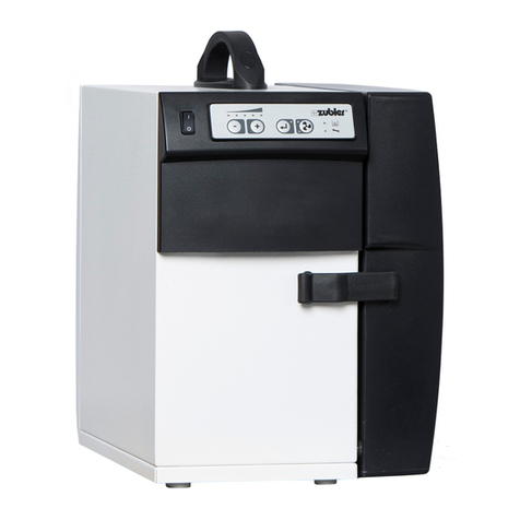
Zubler Z4 VARIOmatic User manual

Z4 VARIOmatic
www.zubler.de
EN 10-2021
Multi suction system

2
Advanced settings are provided by the Zubler Suction-
Technology APP, which is available for Android tablets or
phones.
Therefore follow the users manual of the Zubler Suction-
Technology APP, which is downloadable from www.zubler.de

3
0. User information page 4
0.1 Declaration of conformity
0.2 Intended purpose of use
0.3 Operating Environment
1. Installation of the appliance page 6
1.1 Scope of supply and accessories
1.2 Setting up the suction unit
1.3 Connecting the suction system
1.3.1 Suction
1.3.2 Exhaust
1.3.3 Compressed air
1.4 Connecting the AP601 port openers
1.4.1 Install the port valve
1.4.2 Install the control unit
1.4.3 Connecting the control units
1.5 Intake system
2. Functions page 15
2.1 Control unit
2.2 Commissioning
2.3 Basic functions
2.3.1 Vacuum levels
2.3.2 Starting the suction manually
(for test purposes only!)
2.3.3 Multi-user vacuum level
2.3.4 Central vacuum level mode
3. Maintenance page 17
3.1 Dust removal
3.1.1 Checking the fill level
3.1.2 Adjusting the container timer
3.1.3 Disposal of dust
3.2 Filter cartridges
3.3 Spare parts
4. Error Codes page 22
5. Technical Data page 25
6. Warranty page 26
7. Disposal instructions page 27
Content

4
0.
0.1 Declaration of conformity
Introduction
Dear customer,
we are pleased, that you have decided for a Zubler suction system and hope it
will enhance your work. The continuous development of our technology is based
on the co-operation with experienced dental technicians. The focus lies on the
aim to optimize the extraction technology in the fields of performance, noise and
reliability.
Please read this operating manual carefully in order to ensure a
problem-free operation.
We, Zubler Gerätebau GmbH
Buchbrunnenweg 26
89081 Ulm Jungingen
declare, that the product suction unit
Z4 VARIOmatic
conforms to the health and safety
requirements set out in the directives
2014/30/EC EMV-Directive
2014/35/EC Low-Voltage Directive
2006/42/EC Machines Directive
2011/65/EU RoHS,
Any modification not specifically approved by
us voids the validity of this declaration.
Kurt Zubler
ceo

5
0.2 Intended purpose of use
0.3 Operating Environment
Temperature: +5°C bis +40°C
Max. permissible relative humidity: max. 80% (bei 30°C)
Voltage supply 230V AC +/-5% 50-60Hz
Total connected load : 10A
Compressed air, free of oil and moist min.5,0bar
This suction system is designed exclusively for dry dusts!
The Z4 VARIOmatic is a central suction system for the simultaneous operation
of a maximum of 4 workstations and can be used for up to 10 alternatively used
stations.
The suction system consists of the central suction unit Z4 and port openers
AP601 connected to the suction system via network cable.
The suction system allows working with 5 vacuum levels as long as only one
workstation is opened.
With simultaneous operation of 4 workstation, all stations have regardless of
their setting, the same suction power which corresponds to suction level 2
(factory setting).

6
1. Installation of the appliance
1.1 Scope of supply and accessories
1x Z4 VARIOmatic
suction unit
1x Power cord
Suction hose Ø75mm length 800mm
Exhaust hose Ø75mm length 800mm
Compressed air hose Ø8mm
with quick connector
1x Closure cap for suction port (mounted)
2x Closure plug 75mm
Note: Automatic port openers AP601 will
be included according to the number of
workstations ordered which will come with
their own instructions and accessories.

7
u
v
w
x
19
18
52
51
20
38
31
17 Door removal
Transporting and positioning the suction unit is
much easier with the door (18) removed. The
door can be removed as shown in Fig.1:
ulift the latch of closure (19)
vrotate the latch by 90°.
wswivel the door (18) approx. 10° to the
front.
xnow you can remove the door (18)
completely by lifting it slightly.
Fig. 1
Fig. 2
ZUBLER Gerätebau GmbH
Buchbrunnenweg 26
D-89081 Ulm
Tel. + 49(0)731 1452-0 / www.zubler.de
Absauganlage
Z4
Spannung 230V
Gesamtleistung max. 1800W
Z4 VARIOmatic 00-11111-22
Made in
Germany
17 Exhaust cover
18 Door
19 Closure
31 Dust container
38 Clamping lever
51 Automatic circuit breaker
52 Pressure gauge
Compressed air
QFor queries, service, spare parts and
accessories, you will find the serial number
on the inside of the suction unit, at the
front next to the dust container (31).
Type plate, serial number
1.2. Setting up the suction unit

8
54
53
27
55
57
56
48
49
59
58
450
Set up
QPull down the Clamping lever (38) to
lower the dirt container (31), check if
the container is empty and there are no
accessories in it.
QPlace the suction unit on a level surface.
If necessary, an alignment is possible by
adjusting the height of the threaded feet
up to max. 8mm. see Fig. 3
QThe housing of the suction unit must
not touch furniture parts, to avoid a
transmission of vibrations and noise
amplification.
27 Connectors AP601
48 Suction port, top
49
Suction port, bottom
53 Exhaust air Motor cooling
54 Mains connector
55 Motor silencer
56 Exhaust port
57
Compressed air connector 8mm
58 Pressure reducer
59 Compressed air tank
Backside accessibility
QEnsure that the connections are easily
accessible from the backside or from
the sides, especially the right-side of the
suction unit. Partition walls of furniture
units must be recessed from a depth of
450 mm to the rear, see Fig. 4.
QEnsure that it is possible to pull out
the applliance to the front. This is
necessary for servicing the motor and the
compressed air system.
QThe suction and exhaust air lines can be
connected or disconnected much easier
with the enclosed Ø75mm hose adapters.
A direct connection with pipe is not
recommended and is only possible if the
suction unit is completely accessible.
Fig. 4:
Fig. 3:

9
1.3.1 Suction
QThe suction hose (socket/socket 45°)
Fig. 6 is connected with the angled side
to the suction port of the suction unit.
Furthermore it ensures a correct pipe
installation (pipe pointing to suction)
Article number: 752/3480
one-sided
QIf all workstations are on one side of
the suction system, one of the suction
ports can be closed with a closure cap.
(preinstalled on bottom port 49)
QIf the suction hose must be routed away
within the construction depth of the
suction system, the connection must be
made according to the arrangement in Fig.
5. If necessary, swap the closure cap to
the other port.
two-sided
QIf there are workstations on both sides
of the suction system, both suction
ports (48/49) must be used. Within the
construction depth of the extraction
system, a suction hose leading to the
left can only be connected to the bottom
suction port.
QAn additional suction hose, Fig. 6, item
number 752/3480 is required.
1.3. Connecting the suction unit
Fig. 5:
Fig. 6

10
9
1.3.2 Exhaust
QThe exhaust can be moved to the left or
bottom of the motor silencer (55) by
swapping the exhaust cover (17) and the
exhaust port (56). Fig. 1.
QThe usage of the bottom exhaust port
should be avoided if possible, otherwise
it may not leave enough space for suction
and compressed air lines.
QThe exhaust hose (socket/pipe) Fig. 8 is
used to route the exhaust air from the
suction system to the installed piping. The
exhaust hose can additionally be used as
an extension or flexible intermediate piece
in the suction or exhaust air line. Item
number: 752/3481
QWe recommend to guide the exhaust air
to the outside. If the length of the duct
exceeds 10m, Ø 110mm pipe should be
installed.
QFor an exhaust into the room, we offer
a diffuser (Fig.9), which reduces the air
velocity and outflow noise. This can be
installed in a suitable position and can also
be connected via a Ø75mm pipe.
Dimensions: 450x300x300 mm
Fig. 7:
1.3.3 Compressed air
QPlug the enclosed 8mm compressed air
hose firmly into the swivelling connector
on the pressure reducer, Fig.10, take care
to overcome the pressure point of the
sealing.
QNow the quick connector (7mm) can be
plugged into a suitable quick coupling in
the laboratory.
Fig. 8:
Fig. 10:
Fig. 9:

11
12
2
11
16
75
3
9
62
60
20
B
10
1
1
27
28
A
76
9
8
Fig. 11: Schematic layout of a
workstation with multistation suction
system Z4 VARIOmatic
1 Pipe system
2 Suction hose workstation
3 Port valve
8 Comp. air line port valve
9 Comp. air supply
10 Handpiece control unit
e.g. Zubler K50
11 Handpiece
12 Power cord handpiece
control unit (with 28 only!)
16 Exhaust hose Ø75mm
20 Z4 VARIOmatic Multi-
station suction unit
27 Connectors AP601
28 Start signal K50
60 Autom. port opener AP601
62 Mains cable AP601
75 Network cable
76
Power cord K50
A Suction funnel R2200
B Rectangular pipe R2000
1.4 Connecting the AP601 port openers

12
8
7
5
6
45
61 63
72
69
1.4.1 Install the port valve
QPlug the port valve (3) directly into the
40mm branch pipe.
Q
Connect the port valve and the workstation
with 40mm hose. The Length should not
exceed 1.5m.
1.4.2 Install the control unit
QInstall the control unit with at least 2
screws at the workbench close to the
workstation.
QConnect the compr. air connector (6) of
the port valve with the compr. air connector
(72) of the AP601 control unit, using the
enclosed Ø6mm compr. air hose.
QConnect the compr. air supply (69) of the
AP601 control unit (pressure reducer) with
your local compr. air supply, using the
enclosed Ø8mm compr. air hose.
QPlug the handpiece or other tool into the
IEC C13 socket (63), using the enclosed
C13/C14 power cord adapter.
QIf your working equipment is not equipped
with a C13 socket, you may need a suitable
power adapter which is not included.
QPlug the enclosed power cord into the
IEC C14 power socket (61) of the AP601
control unit and plug it into a local power
socket.
Fig. 12
Fig. 13
4 Valve body
5 Suction ports Ø40mm
6 Compr. air connector
7 Push ring
8
Compr. air hose Ø6mm

13
Fig. 14:
1.4.3 Connecting the control units
QThe AP601 port openers must be connec-
ted to the suction unit via a data bus (Fig.14).
QTherefore use the 3m network cable,
which comes with the AP601.
QThe AP601 is equipped with two RJ45
network sockets, which are used for
interconnection (daisy chaining).
QThe suction unit is also equipped with two
RJ45 network sockets, which only have to
be used both, if there are workstations on
both sides of the suction unit.
It is recommended to route the network
cable parallel to the suction line.
QIf the distance between two neighbouring
AP601 or between an AP601 and the suc-
tion unit is greater than 3m, longer network
cables are required, which are also available
from the Zubler accessory list.
Length Article number
5m 822/0661
10m 822/0662
QFor further information, please refer to the
schematic illustration on page 11 or the
detailed instructions for the AP601 port
opener.

14
A
B
Basic system requirements include optimal
particle flow, minimal noise production and
ergonomic posture promotion.
The following criteria promote these basic
requirements and are specifically adapted to
Zubler suction systems.
QSuction funnel R2200,
QRectangular pipe R2000
QSitting in the upright position in a posture
preserving ergonomically designed chair.
QWorkpiece as close as possible to the
suction funnel R2200; no dust cloud may
be visible. Trails of dust must be drawn
into the hopper.
QDirection of viewing of the workpiece
perpendicular to the protective screen.
1.5 Intake system
A Suction funnel R2200
B Rectangular pipe R2000
Fig. 15
Attention!
The protective glass shield is essential for
the dust collection and must be mounted.

15
2.
T1 T2 T3 T4
L6
L4
L5
29
L2
L3L1
52
L1 LED Vacuum level
L2 LED Bluetooth
L3 LED “ON”
L4 LED Dust container/Filter
L5 LED Service
L6 LED Central vacuum mode
T1 minus-(-)
T2 plus-(+)
T3 Enter
T4 ON / OFF
29 Main switch
QSwitch on the main switch (29).
QAt first, the suction unit opens all
connected port openers AP601 one after
the other for a few seconds to clean the
hoses and pipes from dust deposits with
maximum suction power.
QAfter the hoses have been cleaned, the
filters are cleaned with 6 successive blasts
of compressed air.
Please pay attention to this function
and check that the pressure gauge (52)
reaches 5 bar again after each compressed
air blast Fig.17 (Fig.1, page 7).
QThe suction system is ready when the red
LEDs L4 and L5 stop flashing.
QSettings of the individual suction points
can be made in accordance with the
operating instructions for the AP601.
- Adjustment of the sensitivity for
automatic operation.
- Automatic pipe cleaning for each main
pipe run
- Set the suction level, sequence and
names for the workstations.
Functions
Fig. 16
2.1 Control unit
2.2 Commissioning
Fig. 17

16
T1 T2
-+
Mehrplatz - Einzelplatz (Anlage)
Level suction power
1 20 l/s
2 25 l/s
3 30 l/s
4 35 l/s
5 max 50 l/s
2.3.1 Vacuum levels
QAs long as the power limit of the suction
motor is not reached (depending on
the number of simultaneously opened
workstations), the following volume flows
can be achieved approximately with the 5
factory set vacuum levels:
QVacuum level 5 is the maximum motor
power (no volume control).
QThe specified air volumes are determined
by the attached vacuum and refer to
the port valve diameter of the AP601
automatic port opener.
2.3 Basic functions
QThe suction power of the vacuum levels
1-4 can be changed via the Zubler suction
technology APP.

17
2.3.2 Starting the suction manually
(for test purposes only!)
QThe suction can only be started manually
by pressing T4 ( )on the suction unit,
if there are no AP601 port openers
connected to the suction unit! LED L6
starts flashing once the mode is activated.
QThe vacuum levels can be adjusted with
the T1 (-) and T2 (+) keys.
QOnce there are AP601 port openers con-
nected, button T4
()
on the suction
unit is blocked. Starting the suction is only
possible via the AP601 port openers.
2.3.3 Multi-user vacuum level
QThe multi-user vacuum level is factory set
to level 2. If more than one workstation is
opened, vacuum level 2 is applied.
QThe multi-user vacuum level can be
adjusted with the T1 (-) and T2 (+) keys
and can be saved by pressing T3 (Enter).
2.3.4 Central vacuum level mode
QUsually the vacuum level is defined by the
AP601 port openers. However, under some
circumstances a central vacuum level mode
may be required. With this mode all work-
stations use the same vacuum level regard-
less of the vacuum levels of the AP601
port openers.
QThe central vacuum level can be adjusted
with the T1 (-) and T2 (+) keys and can
be saved by pressing T4 ( ). LED L6 is
lighted. Press T4 ( ) again to disable the
mode again.
Q
The status of the central vacuum level mode
is saved even after a restart of the suction unit.
Further system settings are possible with the
Zubler suction technology APP.
T3
T4
T1 T2
-+
T4
Mehrplatz - Einzelplatz (Anlage)
T1 T2
-+
Mehrplatz - Einzelplatz (Anlage)

18
3.
35
31
38
Maintenance
Fig. 18
Maintenance
3.1.1 Checking the fill level
QOnce the timer for the dust container has
expired, the LEDs L4 (dust container) and
L5 (service) start flashing. Next time the
suction unit is switched ON, the unit stops
working and the dust container (31) must
be checked as follows:
QLeave the suction unit switched ON
QRemove the door (18) as described in
section 1.2 and lower the clamping lever
(38). The LED L5 (dust container) stops
flashing and is permanently lit.
QPull out the dust container and empty it if
necessary, according to section 3.1.3.
QSlide the dust container back into the
suction unit until limit stop and pull the
clamping lever upwards.
QThe LEDs L4 and L5 are blanked and the
timer is reset.
3.1.2 Adjusting the container timer
QThe dust container timer is factory set to
40h motor running time. Initially you may
have to check the filling of the dust con-
tainer dayly or weekly to evaluate the
expected amount of dust.
QIf the dust container is already filled more
than half after one week, the interval
should be shortened.
QIf the container timer is too short, we re-
commend adjusting it only, if the dust
container is less than 1/3 full of dust once
the timer has expired.
3.1 Dust removal
31 Dust container
35 Filter cover
38 Clamping lever
QChange the container timer according to
the instructions for the Zubler suction
technology APP.

19
u v w x
3.1.3 Disposal of dust
ATTENTION!
Sealing edge!
Must not be
be damaged.
Fig. 19
Fig. 20
For the following work, gloves and a mouth
guard should be used to safely protect the
skin and respiratory tract.
QKeep 2 commercially available drawstring
waste bags 60l with a width of 63-64cm
ready.
QPull the dust container slowly out towards
the front.
QPull off the waste bag from the inner rim
of the sealing channel and close the draw-
string before slowly lifting the filled bag
upwards out of the container. (Fig.20)For
safe transport out of the laboratory, another
bag should be pulled over the dust-filled bag.
QClean the container and pay particular
attention to the cleanliness and integrity of
the two circumferential sealing rims of the
channel Fig.19 .
QUnfold the new bag, pull it with the draw-
string over the inner rim of the sealing
channel and push the bag into the con-
tainer avoid overlapping over the outer
container edge.
QCarefully slide the container back into the
suction unit and pull it up against the sealing
with the clamping lever.

20
35
31 38
24
Fig. 21
Q
The Z4 VARIOmatic is equipped with 3 filter
cartridges (24) that must be replaced to-
gether when their efficiency is no longer
given.
QIf no increase of suction power is reached
after 3 successive cleaning cycles, the
filter cartridges must be replaced.
QThe LEDs L4 (dust container) and L5
(service) are lit permanently.
QIf this condition is already reached after
less than a year, the lifetime may be
extended by shortening the cleaning
interval.
Q
Switch off the unit at the mains switch (29).
QRemove the door (18) and put it aside.
QLoosen the 8 pcs. M4 nuts on the filter
cover (35) with a 7mm socket wrench
and pull off the filter cover (35) from the
threaded bolts.
Respiratory protection and gloves must be
used for further steps! For the soiled dirty
filters, have a suitable waste bag ready.
3.2 Filter cartridges
24 Filter cartridge
31 Dust container
35 Filter cover
38 Clamping lever
Table of contents
Other Zubler Dental Equipment manuals
Popular Dental Equipment manuals by other brands

Amanngirrbach
Amanngirrbach laserpin user manual

Micromega
Micromega HEROfill Obturator n 20 operating instructions

Amanngirrbach
Amanngirrbach MILLING UNIT 5X Instructions for use

Pac-Dent
Pac-Dent PROMATE CL instruction manual

DentalEZ
DentalEZ Heritage user manual

B.A. International
B.A. International Optima OS600L Instructions for use

SAESHIN
SAESHIN TRAUS ATN400 instruction manual

Heraeus
Heraeus PALA Palamat elite Operating instruction

NSK
NSK S-Max pico QD Operation manual

ROLENCE ENTERPRISE
ROLENCE ENTERPRISE ELiTEDENT Q-6 user manual

Durr Dental
Durr Dental VistaScan Nano Easy Installation and operating instructions

Acteon
Acteon I-Surge user manual