Zumtobel ONLITE local SB 128 Controller User manual

ONLITE local
SB 128 Controller
Operating instructions
with quick commissioning
guide and installation check
list
Art. No.: 00072417


ONLITE local SB 128 Controller 1
Contents
Copyright .......................................................................................................................5
Manufacturer address................................................................................................... 5
Validity and technical state of this manual................................................................. 5
1 Notes regarding security and use of the operating instructions...................... 6
1.1 Use of symbols and identification of security notes........................................ 6
1.2 Important notes regarding industrial and operational safety .......................... 7
1.3 Notes on illustrations and circuit diagrams..................................................... 7
2 Product description............................................................................................... 8
2.1 Specified use.................................................................................................. 8
2.2 Description ..................................................................................................... 9
2.3 Example circuit diagram ............................................................................... 10
2.4 Technical Data ............................................................................................. 11
2.5 Communication and data exchange ............................................................. 12
2.5.1 Communication and data exchange interfaces .................................. 12
2.5.2 DALI bus ............................................................................................ 13
3 Installation............................................................................................................ 14
3.1 Who is allowed to perform the installation?.................................................. 14
3.2 Mounting the ONLITE local SB 128 Controller ............................................. 14
3.3 Connecting the DALI bus ............................................................................. 15
3.4 Connecting the ONLITE local Switch module .............................................. 16
3.5 Connecting a GSM module .......................................................................... 17
3.6 Connecting a remote display device ............................................................ 19
3.6.1 System and error messages assignment ........................................... 21
3.7 Connecting the ONLITE local Extender ....................................................... 22
3.8 Connecting the ONLITE local Repeater ....................................................... 23
3.9 Connecting the 230 V mains supply ............................................................. 24
3.10 Completing the installation ........................................................................... 24
4 Commissioning.................................................................................................... 25
4.1 Important notes prior to commissioning ....................................................... 25
4.2 General notes concerning operation ............................................................ 25
4.2.1 Control keys on the touch panel......................................................... 26
4.2.2 LEDs on the device ............................................................................ 29
5 Main menu............................................................................................................ 30
5.1 Overview ...................................................................................................... 30
5.2 Display.......................................................................................................... 30

2 ONLITE local SB 128 Controller
6 Quick menu.......................................................................................................... 31
6.1 Block system ................................................................................................ 31
6.2 Start function test ......................................................................................... 32
6.3 Start duration test......................................................................................... 33
7 Test functions...................................................................................................... 34
7.1 Overview ...................................................................................................... 34
7.2 Test book ..................................................................................................... 34
7.3 Automatic function test................................................................................. 35
7.4 Automatic duration test ................................................................................ 36
7.5 Inspection test .............................................................................................. 38
7.6 Relay / buzzer test ....................................................................................... 38
8 Luminaires ........................................................................................................... 39
8.1 Overview ...................................................................................................... 39
8.2 Luminaires status ......................................................................................... 39
8.3 Luminaires settings ...................................................................................... 40
8.4 Luminaires setup.......................................................................................... 42
8.5 Setting up groups with ONLITE local Extender............................................ 47
9 Message assignments to relays / buzzer / GSM............................................... 50
9.1 Overview ...................................................................................................... 50
9.2 Status ........................................................................................................... 50
9.3 Assignments................................................................................................. 50
10 Connected devices ............................................................................................. 52
10.1 Overview ...................................................................................................... 52
10.2 ONLITE GSM module .................................................................................. 52
10.3 Printer........................................................................................................... 55
10.4 IrDA interface ............................................................................................... 55
10.5 ModBus ........................................................................................................ 57
11 System (equipment) configuration.................................................................... 58
11.1 Overview ...................................................................................................... 58
11.2 Options......................................................................................................... 58
11.3 Display ......................................................................................................... 59
11.4 Service ......................................................................................................... 59
12 Error checklist for luminaires operated on an SB 128 controller................... 61
12.1 Using the error detection tables ................................................................... 61
12.2 Luminaire cannot be found during re-initialisation or system extension....... 62
12.3 Luminaire is reporting communication error during operation...................... 64
12.4 Luminaire is reporting lamp error during operation ...................................... 65
12.5 Luminaire is reporting battery error .............................................................. 66

4 ONLITE local SB 128 Controller

ONLITE local SB 128 Controller 5
Copyright
Without the expressed written permission of Zumtobel Lighting GmbH, no part of this
manual may be reproduced, published or transmitted in any form or by any means.
© 2006 Zumtobel Lighting GmbH. All rights reserved.
Manufacturer address
For information, support concerning technical problems, services and orders we are at
your disposal.
Zumtobel Lighting GmbH
Schweizer Straße 30
6851 Dornbirn, Austria
Phone: +43 (0) 5572 390-0
Validity and technical state of this manual
This operating manual only relates to devices of the type ONLITE local SB 128 Controller
with the article number 22 156 829.
Technical modifications made after printing this manual are not considered. Subject to
changes.
Issue date: Version 06/2013 June 2013

6 ONLITE local SB 128 Controller
1 Notes regarding security and use of the operating
instructions
1.1 Use of symbols and identification of security notes
Instruction
This symbol indicates that the described instruction has to be performed by the
user.
Displays and messages
This symbol indicates that the described values or texts are shown in the display
or contained in messages and can not be edited.
Note
This symbol represents a reference to hints and recommendations which are
useful when performing the instructions and handling the device or system
components.
Caution!
This symbol warns of improper handling. Disregarding the instructions may result
in damages to system components.
Warning!
This symbol points to sources of danger which may cause personal injuries or
severe damages to system components.
Danger!
This symbol points to sources of danger which may cause critical personal
injuries or acute damages to system components.

ONLITE local SB 128 Controller 7
1.2 Important notes regarding industrial and operational safety
The device is part of the emergency and general lighting and consequently part of a
building's safety equipment. Thus, appropriate care and precision are to be applied when
installing and commissioning the system.
Warning!
Non-authorised or non-professional system installation and handling may result
in outages of the safety equipment. This implies immediate danger for people and
the security equipment itself. In addition, damages to machines and plants as well
as loss of productions are possible consequences at production sites.
During normal operation, the following maintenance operations have to be performed
continuously:
• Regular checking and inspection of the system.
• Inspection and logging of device functions.
• Safety measures in the event of failures.
Note
Inspections, safety tests and documentation are restricted to authorised technical
staff.
National laws and guidelines are to be observed, regarding
• execution of inspections and safety tests and
• implementation of general and emergency lighting.
1.3 Notes on illustrations and circuit diagrams
Illustrations and circuit diagrams in these installation and operating instructions are partly
for demonstration purposes only. Drawings and plans that were especially created for the
lighting system and are in accordance with local requirements must be observed.

8 ONLITE local SB 128 Controller
2 Product description
2.1 Specified use
The ONLITE local SB 128 Controller is intended for central controlling and monitoring of
emergency lighting systems. Parameterisation and operation of the system is restricted
to authorised technical staff.
Personal danger may occur in case of
• improper use or
• non-observance of safety regulations.
The device and connected system components may only be operated if these are in
perfect technical condition and in compliance with
• the safety and danger notes contained in these installation instructions,
• operating and safety instructions stipulated by the system operator,
• the installation and operating data listed in section 2.4 on page 11.
Failures are to be reported to management and rectified.
Operating and safety regulations arise from these installation instructions as well as
organisational instructions by management, and general as well as technical guidelines
and regulations for accident prevention.
The manufacturer will not assume warranty or liability for consequential damages that
occur due to:
• improper use,
• non-observance of regulations,
• unauthorised modifications or modifications made by technically non-competent
persons to device connections and settings,
• operating unauthorised or unsuitable devices or device groups.
Caution!
Also pay attention to all laws, norms and guidelines applicable in the country in
which the system is being installed and operated.
Verify whether electrical installations comply with the application environment.
Verify whether all used ballasts and luminaires fulfil the requirements of an
emergency lighting system and the operation of an ONLITE system.

ONLITE local SB 128 Controller 9
2.2 Description
The ONLITE local SB 128 Controller centrally controls and monitors single battery supplied
emergency luminaires of the types ONLITE local and ONLITE Emergency Set via the DALI
bus. Devices for the following busses are supported:
•DALI(
Digital Addressable Lighting Interface
, device type 1)
•eD(extended
protocol based on the DALI connection
, device type 1)
The ONLITE local SB 128 Controller allows to monitor two groups with 64 luminaires each.
The maximum cable length from the controller to the last luminaire can be up to 300 m (line
cross section at least 1.5 mm²). By using ONLITE local Extender modules, the complete
installation can be expanded to 256 monitored luminaires and in this case the maximum
cable length may be up to 600 m.
All settings of the ONLITE local SB 128 Controller are stored to a non-volatile memory. Due
to this, the settings will not get lost even if the device is completely switched off. Via the
infrared interface on the controller’s front panel, a PC or a PDA can be connected. This
way, the configuration of the ONLITE local SB 128 Controller and the test book can be
transmitted to the PC or the PDA for the purpose of data storage.
The ONLITE local SB 128 Controller monitors the emergency luminaires by communicating
via the DALI bus. Each single emergency luminaire is monitored individually and the result
is indicated on the display. In parallel to the operation of the ONLITE local SB 128
Controller, lighting control commands (e.g. issued via the EMOTION touch panel) can be
transmitted via the DALI bus. This allows the operation of emergency lighting luminaires as
a part of the general lighting without having additional installation efforts.
The ONLITE system provides the following supplementary functions:
• Automatic addressing and monitoring of luminaires
Each ONLITE local emergency luminaire is detected by the ONLITE local SB 128
Controller and assigned to the corresponding DALI group. Consequently, each
luminaire can be monitored and operated individually.
• Potential-free signaling contacts for remote indication of the operating state
Three potential-free signaling contacts are available for the remote indication of the
ONLITE local system’s operating state. The system events can be freely assigned to the
signaling contacts.
• Failure reports and luminaire configuration via GSM-mobile radio communication
(optional)
The ONLITE GSM module, which can be connected to the ONLITE local SB 128
Controller, allows to easily configure the luminaires via any MFV telephone when
commissioning the installation. Using a GSM mobile phone, failure reports of the
controller can also be received via the SMS service.
• Printing of test logs (optional)
The ONLITE IR-Printer, which can be connected to the ONLITE local SB 128 Controller
via the infrared interface, allows to print the recorded test logs and the current
configuration of the system.

10 ONLITE local SB 128 Controller
2.3 Example circuit diagram
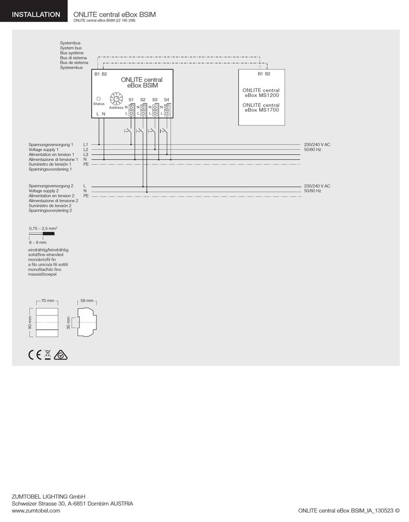
Figure 1: Example circuit diagram of the ONLITE local check system

ONLITE local SB 128 Controller 11
2.4 Technical Data
Item name
Designation:
Art.-No.:
ONLITE local SB 128 Controller
22.156.829
Power supply
Supply voltage:
Mains frequency:
Power consumption:
230 V AC ± 10 %
50 to 60 Hz
10 W max.
Connections
Connections: Mains, 2 x DALI, 3 potential-free signaling contacts,
infrared, RS 232
Infrared interface
Transfer rate:
Transfer protocol:
Range of transmission:
19.2 - 115 kBaud
irDA, IR printer protocol
0.5 m
RS 232 interface
Transfer rate:
Transfer protocol:
Maximum cable length:
19.2 - 115 kBaud
8 bit, 1 start bit, 1 stop bit, no parity
3m
Housing
Dimensions L/W/H:
130 / 155 / 65 mm
Figure 2: ONLITE SB 128 Controller mechanical
characteristics
Weight
Weight (mass): 0.7 kg
Allowed temperature range:
Storage:
Operation:
-20°C…+80°C
0°C…+40°C

12 ONLITE local SB 128 Controller
2.5 Communication and data exchange
2.5.1 Communication and data exchange interfaces
IR interface
The IR interface located on the ONLITE local SB 128 Controller front panel establishes a
direct connection to the ONLITE IR-Printer or to an external PC (e.g. a Notebook). Via
this interface, the current configuration data as well as the test logs can be read out.
RS 232 interface
The serial RS 232 interface allows the data exchange with the optional GSM module.
Protection type
Protection type:
Protection class:
IP20 according to DIN EN 60 529
Class 1 according to DIN EN 60 529
Optional modules
ONLITE IR-Printer: Infrared printer for printing test logs and system
configuration data.
ONLITE GSM Module: GSM mobile radio communication for setting up
luminaires and reporting failure messages via SMS
(Short Message Service).
ONLITE local Extender: Allows expansion from 128 to 256 emergency
luminaires. One ONLITE local Extender module is
able to handle a maximum of 64 emergency
luminaires (see also the circuit diagram on page 10).
ONLITE local Repeater: Allows extending the DALI line with up to 300 m.
ONLITE local Switch Module: Permits independent switching from maintained to
non-maintained of up to four emergency lighting
groups or individual luminaires of an emergency
lighting group connected to the SB 128 controller.
ONLITE local Remote Interface: Is used to remotely display the emergency lighting
system operating status via LEDs.

ONLITE local SB 128 Controller 13
2.5.2 DALI bus
The DALI bus (Digital Addressable Lighting Interface) is used for the communication of
the ONLITE local SB 128 Controller with ONLITE local emergency luminaires and for
connecting general lighting DALI luminaires. The ONLITE local SB 128 Controller
provides two separate DALI busses with an integrated bus supply (terminals A-D1, A-D2
for bus A and terminals B-D1, B-D2 for bus B).
Figure 3: Application example of integrating general lighting luminaires into the
ONLITE local check system through the DALI bus
The possibly available general lighting connected to the same bus is not affected by the
ONLITE local SB 128 Controller and can be controlled using an EMOTION Touch module
or LM-DALI, for instance.

14 ONLITE local SB 128 Controller
3Installation
Warning!
Only qualified electrical specialists may perform work on the 230 V mains supply.
Wiring of current-carrying lines as well as signal and control lines must be done
in accordance with the relevant guidelines and norms.
National guidelines and regulations applicable in the country in which the system
is being installed and operated have to be observed.
3.1 Who is allowed to perform the installation?
In principle, the installation may only be performed by suitably qualified professional
electrical specialists who have been briefed on local and operational conditions. Other
persons may only perform the installation under the supervision and control of authorized
technical staff, after having received appropriate briefing and if the tasks and jobs have
been fully understood.
3.2 Mounting the ONLITE local SB 128 Controller
The ONLITE local SB 128 Controller can be mounted using the drilling holes in the rear
panel or on a top-hat rail according to EN 50022.
The required drilling hole distances can be found in the accompanying drawing.
The drilling hole diameter is 3.5 mm.
Figure 4: Mounting the SB 128 Controller

ONLITE local SB 128 Controller 15
3.3 Connecting the DALI bus
Connect the cable for the first DALI bus to terminals A-D1 and A-D2 and the cable of the
second bus to terminals B-D1 and B-D2. The cable polarity is insignificant.
Please observe the required line cross sections:
• up to 100 m 0.5 mm2
• 100 m - 150 m 0.75 mm2
• 150 m - 200 m 1.0 mm2
• 200 m - 300 m 1.5 mm2
Recommendation: Always use a line cross section of 1.5 mm2.
Figure 5: Creating a DALI connection with the ONLITE SB 128 Controller

16 ONLITE local SB 128 Controller
3.4 Connecting the ONLITE local Switch module
The ONLITE local check Switch module is a DALI input device for independent switching
from maintained to non-maintained of up to four emergency lighting groups or individual
luminaires of an emergency lighting group connected to the SB 128 controller.
Caution!
The ONLITE local Switch module must not be used together with light controllers
of the types Emotion Touch or LM-DALI.
The ONLITE local Switch module may only be connected to group 1 of the ONLITE local
SB 128 Controller. It provides four switching inputs (S1 to S4) which can be used for an
individual switching of security luminaires and/or emergency exit sign luminaires. The
push button inputs may only be operated potential-free.
Figure 6: Connecting the ONLITE local Switch module to the ONLITE local
SB 128 Controller

ONLITE local SB 128 Controller 17
3.5 Connecting a GSM module
The ONLITE GSM module is intended as an additional module for the ONLITE local
SB 128 Controller. It enables the communication between the controller and a standard
telephone. Even telephone conversations are possible via the integrated microphone and
speaker. The GSM module enables the ONLITE local SB 128 Controller to send
messages (e.g. failure messages) to a mobile phone using the SMS service (Short
Message Service). Conversely, it is also possible to issue commands to the ONLITE local
SB 128 Controller using the buttons of a tone-dialling telephone.
Warning!
Prior to clamping, both the ONLITE local SB 128 Controller and the device to be
connected must be switched dead.
The ONLITE GSM Module is connected to the controller's RS 232 interface as follows:
Connect the RS 232 cable to the terminals Rx, Tx and Gnd of the ONLITE local SB 128
Controller. Connect the other end of the RS 232 cable to the terminals Rx, Tx and Gnd
of the ONLITE GSM module.
Figure 7: Creating a RS 232 connection with the ONLITE SB 128 Controller
Caution!
Ensure that the same wires are connected to the terminals with identical labels at
both devices. The maximum allowed RS 232 cable length is 3 meters.
Furthermore, take note of the information given in section 2.4 on page 11.
RS 232 cable

18 ONLITE local SB 128 Controller
Figure 8: Connecting the ONLITE GSM module to the ONLITE local SB 128
Controller
This manual suits for next models
1
Table of contents
Other Zumtobel Controllers manuals
Popular Controllers manuals by other brands

Plast-O-Matic
Plast-O-Matic CAFE Installation, operation & maintenance instructions

KiWi Lighting
KiWi Lighting TopLedLight BY-CON-DR1903A manual

Clean Logix
Clean Logix ALX-ELITE user manual

Ebmpapst
Ebmpapst CGCXX00000 Operating and maintenance instructions

XPR Access
XPR Access WS4-1D quick start guide

Lily Tech
Lily Tech ZL-6280A instruction manual