ZyXEL Communications SHD1112 User manual

1
SHD1112
MOTION DETECTOR
The Motion Detector is a Z-WaveTM enabled device and is fully compatible with any
Z-WaveTM enabled network. Z-WaveTM enabled devices displaying the Z-WaveTM
logo can also be used with it regardless of the manufacturer, and ours can also be
used in other manufacturer’s Z-WaveTM enabled networks. This Motion Detector is
controllable to our modules, such as On/Off Module SHD2110 and Lamp Module
SHD2210. Inclusion of this Motion Detector on other manufacturer’s Wireless
Controller menu allows remote turn-on of connected modules and their connected
lighting when the Detector is triggered. Z-WaveTM nodes in the system also act as
repeaters if they support that function.
The Motion Detector is designed to detect movement in a protected area by
detecting changes in infra-red radiation levels caused, for example, when a person
moves within or across the devices field of vision, a trigger radio signal will be
transmitted.
Adding to Z-WaveTM Network
In the rear casing, there is a tamper switch which is used to carry out inclusion,
exclusion or association. Put a Z-WaveTM Wireless Controller into
inclusion/exclusion mode, press the tamper switch on the detector to complete the
inclusion/exclusion process. The Motion Detector supports one association group
with five nodes. This has the effect that when the Detector trigger, all devices
associated with Detector will be operated.
The Motion Detector will stay “awake”for ten minutes when changing the status of
tamper switch from being pressed to be released or from being released to be
pressed to allow time for configuration. (FIGURE 1)
FIGURE 1
Choosing A Mounting Location
The recommended position for a Motion Detector is in the corner of a room
mounted 2m from the floor. At this height, the detector will detect movement
up to 6-12m depending on adjustment. (FIGURE 2a) Also, in this position, the
100 degrees fan-shaped detection pattern can normally offer greater protection
than mounting on a flat wall. Before selecting a position for a Motion Detector
the following points should be noted:
1. Do not position the detector facing a window or direct sunlight. Motion
Detectors are not suitable for use in conservatories or draughty areas.
2. Do not position the detector directly above orfacing any source of heat, eg:fires,
radiators, boiler etc.
3. Where possible, mount the detector so that the logical path of an intruder would
cut across the fan pattern rather than directly towards the detector.(FIGURE
2b)
FIGURE 2a FIGURE 2b
Installation
60 2
2.0
2
0
10
6
(M)
10 (M)
100°
4 8
4
8
2
4
6
8
10

2
Front Cover
Battery
Motion Sensor
Rear Cover
Time-off Knob
Tamper Switch
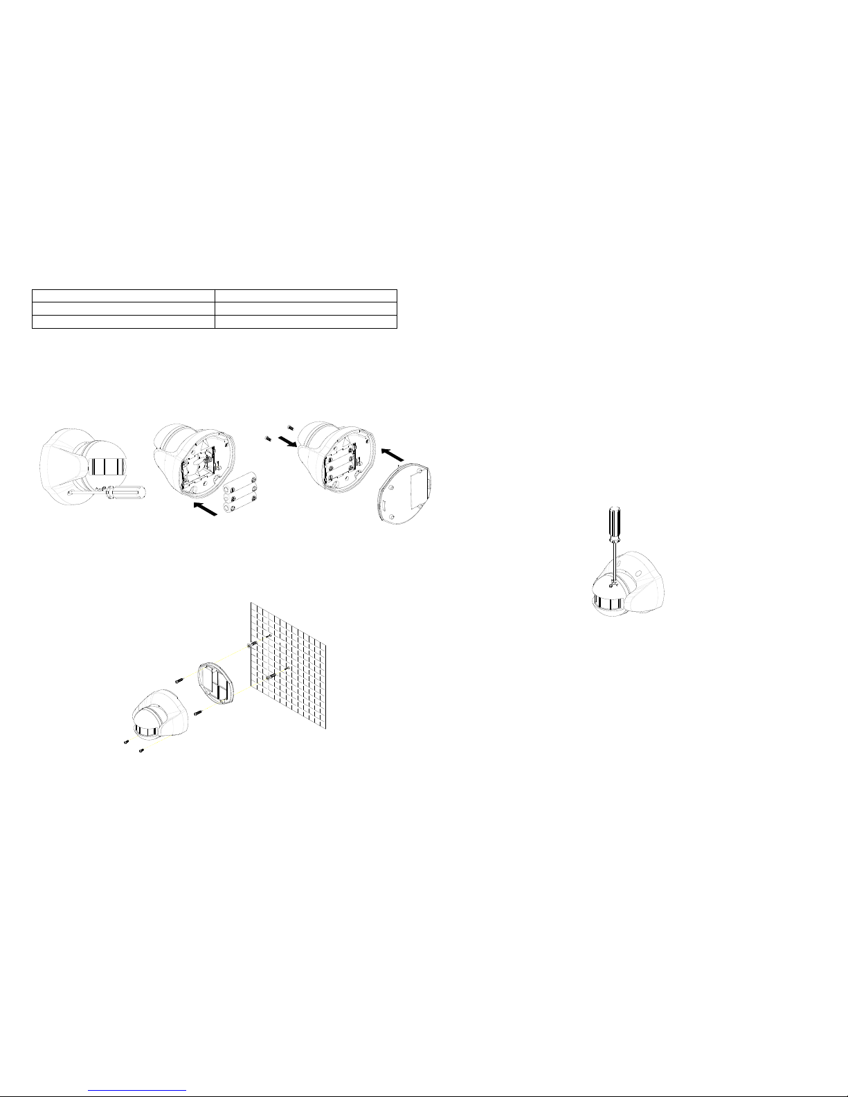
1. Use a Phillips screwdriver to detach the rear cover. (FIGURE 3a)
2. Insert 3 AA-size 1.5V batteries to the battery compartment, ensuring that
correct polarity is put. (FIGURE 3b)
Note: The adoption of alkaline battery is highly recommended, as it would last
for longer period.
3. Refit the rear cover. (FIGURE 3c)
FIGURE 3a FIGURE 3b FIGURE 3c
4. Hold the rear cover in position and mark the two mounting holes. Drill the holes,
insert the plastic wall plugs and screw the rear cover to the wall using the
screws supplied. Offer the Detector up to the rear cover using screws as
originally supplied. (FIGURE 4)
FIGURE 4
Note: After removing batteries, wait for 5 seconds to refit batteries.
Operation
1. With the tamper switch not being pressed, the unit enters test mode, which
allows the user to make a test. When the movement has been detected, the
red indicator LED on the Detector will illuminate and the load or the lamp
plugged into the On/Off Module SHD2110, Lamp Module SHD2210 will turn ON.
It implies that the unit is working properly.
Note: When the battery is connected, the LED behind the lens will be on for
about 1 minute as warming-up duration until the Motion Sensor has stabilized
when the LED turns OFF.
Time-off knob controls how long the connected load or lamp will stay on after
the motion has been detected. It is set from 5 seconds to 12 minutes. “T”
means 5 seconds, while “+”is 12 minutes. After the expiry of preset time-off, the
Detector will turn OFF the load or the lamp plugged into the On/Off Module
SHD2110, Lamp Module SHD2210. The red indicator LED on the load or the
connected lamp will be off too.
2. When the tamper switch is pressed, the unit will enter normal mode. Upon
motion being sensed, the Detector will turn ON the load or the lamp plugged
into the On/Off Module SHD2110, Lamp Module SHD2210.
After the elapse of preset time-off, the Detector will turn OFF the load or the
lamp plugged into the On/Off Module SHD2110, Lamp Module SHD2210.
In normal mode with the tamper switch being pressed, the red indicator LED on
the Detector will not illuminate to conserve battery life when the detector is
triggered, (unless the battery is low).
3. By pressing the tamper switch for more than 5 seconds, and then release it.
The Detector will send an alarm command (ALARM_REPORT, Alarm Type ==

3
0x01, Alarm Level == 0x11) to the Module. The load or the lamp plugged into
the On/Off Module SHD2110 or Lamp Module SHD2210 will flash for 10
seconds.
Advanced Operation
The following information is for someone that has some experience setting up a
Z-Wave system or someone that has computer software running a Z-Wave
controller.
Enabling/Disabling Power Saving Function (for testing)
When no movement has been detected for 10 seconds, the SHD1112 will enter the
power saving mode. It can be disabled or enabled power saving function by setting
Configuration Parameter # 3.
This parameter can be configured with the value of 0 through 127, where 0 means
power saving being enabled and others mean power saving being disabled.
Note: As long as the batteries have been refitted, the Detector will enable the
power saving function automatically.
Configuring the Phase Level of ON Command
The Configuration parameter that can be used to adjust the phase level of ON
command is transmitted is Configuration Parameter # 1. This parameter can be
configured with the value of 0 through 127.
Value 0: Set Device OFF(0x00)
Value 1-99: Set Device On (1-99)
Value 100-127: Set Device On to the last phase (0xFF)
Note: 0xFF means the device will be on to the last phase before the device was
turned off.
Wakeup Command Class
The Motion Detector will send a Wakeup Notification Command if it has been
included into a Z-Wave network. The prerequisite is the connected Z-Wave
controller needs to emit a node ID and wakeup time interval to the Detector.
The Motion Detector will wake up periodically as desired depending on time interval
you set from wake up command class and resend the Wakeup Notification
Command unless configured for another time interval. The Motion Detector will stay
awake for 10 seconds and then go back to sleep to conserve battery life.
The time interval between Wakeup Notification Commands can be adjusted if you
have a device in which that is supported. Refer to that device’s instructions.
Troubleshooting
Symptom
Possible Cause
Recommendation
Cannot carry out
inclusion and association
1. Run out of battery
power
2. Check if reverse
battery polarity
3. Check if the detector
is out of order
1. Replace a new
battery
2. Refit the battery
with correct polarity
3. Ensure the
detector is
working properly
Cannot control the
connected modules
1. Run out of battery
power
2. Check if the detector
is out of order
1. Replace a new
battery
2. Ensure the
detector is working
properly
The detector not working
1. Run out of battery
power
2. Check if the mounting
location is proper
3. Check if the detector
is mounted above a
radiator or heater
4. Check if the detector
is out of order
1. Replace a new
battery
2. Reposition its
mounting location
3. Remove the
source of
interference or
reposition its
mounting location
4. Ensure the
detector is working
properly

4
Specifications
Battery
1.5V AA size x 3
Range
Up to 100 meters line of sight
Warm Up Time
About 1 minute
PIR Detection Coverage
Up to 10m x 100°(at 2m mounting height & below 20°C)
Frequency Range
908.42 MHz (US) / 868.42 MHz (EU)
*Specifications are subject to change without notice A501110874R03
Federal Communication Commission Interference Statement
This equipment has been tested and found to comply with the limits for a Class B
digital device, pursuant to Part 15 of the FCC Rules. These limits are designed to
provide reasonable protection against harmful interference in a residential
installation. This equipment generates, uses and can radiate radio frequency
energy and, if not installed and used in accordance with theinstructions, may cause
harmful interference to radio communications. However, there is no guarantee
that interference will not occur in a particular installation. If this equipment does
cause harmful interferenceto radio or television reception, which can be determined
by turning the equipment off and on, the user is encouraged to try to correct the
interference by one of the following measures:
- Reorient or relocate the receiving antenna.
- Increase the separation between the equipment and receiver.
- Connect the equipment into an outlet on a circuit different from that to which the
receiver is connected.
- Consult the dealer or an experienced radio/TV technician for help.
This device complies with Part 15 of the FCC Rules. Operation is subject to the
following two conditions: (1) This device may not cause harmful interference, and (2)
this device must accept any interference received, including interference that may
cause undesired operation.
FCC Caution: Any changes or modifications not expressly approved by the party
responsible for compliance could void the user's authority to operate this
equipment.
This transmitter must not be co-located or operating in conjunction with any other
antenna or transmitter.
WARNING:
Do not dispose of electrical appliances as unsorted municipal waste, use separate
collection facilities.
Contact your local government for information regarding the collection systems
available.
If electrical appliances are disposed of in landfills or dumps, hazardous substances
can leak into the groundwater and get into the food chain, damaging your health
and well-being.
When replacing old appliances with new ones, the retailer is legally obligated to take
back your old appliance for disposal at least for free of charge.
Other ZyXEL Communications Accessories manuals