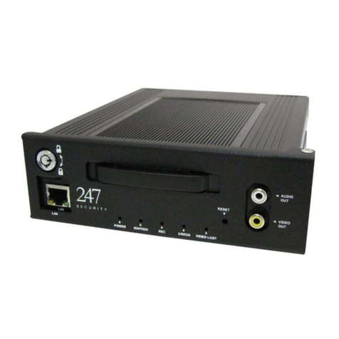
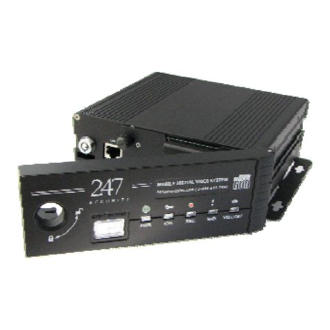
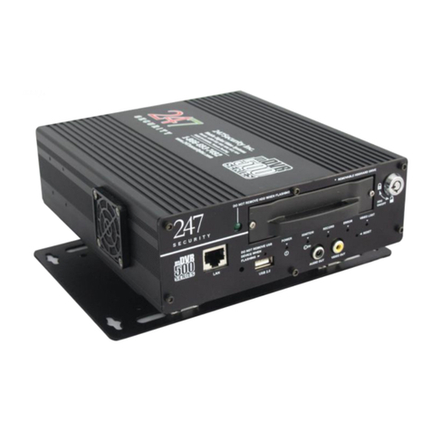
247Security mDVR400 Series User manual

Copyright © 2009, 247Security Inc. | 4400 North Point Parkway, Suite # 158, Alpharetta, GA 30022, USA | 1-866-693-7492 | www.247securityinc.com
USERS MANUAL
mDVR400 Series

247Security Inc. | 4400 North Point Parkway, Suite # 158, Alpharetta, GA 30022, USA | 1-866-693-7492 | www.247securityinc.com
NOTICE
No part of this document may be reproduced, transmitted, transcribed, stored in a
retrieval system, or translated into any language or computer language, in any form or
by any means, electronic, mechanical, magnetic, optical, chemical, manual, or
otherwise, without the prior written permission of 247 Security Inc.
DISCLAIMER
The information in this document is provided for reference purpose only. 247Security
Inc. does not assume any liability for the use of this information or any products
described in this document. Users are advised to take all necessary precautions in
handling, interfacing and using this product along with any peripheral devices. Please
consult the manufacturers of the respective peripheral for specific interface
requirements and precautions.
The information in this manual is subject to change without notice.
If you require further information please contact 247 Security technical support.
TECHNICAL SUPPORT
Technical support is available from 8:30 AM to 5:30PM, Eastern Time:
By phone 1-866-693-7492
TRADE MARKS
Intelligent Thermal Management is registered Trade-Marks of 247 Security Inc.
UNIX is a registered trademark of AT&T Bell Laboratories.
Pentium and x86 are registered trademarks of Intel Corporation.
PC, PC/XT, PC/AT are trademarks of International Business Machines.
MS-DOS and Windows are registered trademarks of Microsoft Corporation.
Copyright ©2005 247 Security Inc®. All rights reserved
No part of this manual may be reproduced in any form or by any means without the
expressed written permission of 247 Security Inc.
1

247Security Inc. | 4400 North Point Parkway, Suite # 158, Alpharetta, GA 30022, USA | 1-866-693-7492 | www.247securityinc.com
CONTENTS
1 DVR400 PRODUCT DESCRIPTION 6
1.1 INTRODUCTION ...............................................................................................................................6
1.2 DVR400 SERVER FEATURES .........................................................................................................6
1.3 CLIENT FEATURES.........................................................................................................................7
2 HARDWARE SPECIFICATIONS 9
2.1 HARDWARE OVERVIEW .................................................................................................................9
2.2 COMPRESSION ................................................................................................................................9
2.3 RECORDING RESOLUTION..............................................................................................................9
2.4 FRAME RATE...................................................................................................................................10
2.5 VIDEO AUDIO RECORDING CHANNELS .........................................................................................10
2.6 REMOVABLE STORAGE MEDIA .....................................................................................................10
2.7 GPS...................................................................................................................................................10
2.8 INDUSTRIAL STANDARD INTERFACES ........................................................................................10
2.9 WIRELESS INTERFACE (OPTIONAL) ............................................................................................11
2.10 ALARM OUTPUTS............................................................................................................................11
2.11 SENSOR INPUTS .............................................................................................................................11
2.12 POWER REQUIREMENT..................................................................................................................11
2.13 IGNITION SIGNAL / POWER DOWN TIMER DELAY OFF...............................................................11
2.14 REAL TIME CLOCK..........................................................................................................................11
2.15 ENVIRONMENTAL...........................................................................................................................11
2.16 MECHANICAL ..................................................................................................................................11
3 SYSTEM OVERVIEW 12
3.1 FRONT VIEW..............................................................................................................................14
3.2 BACK VIEW................................................................................................................................15
4 CONNECTING TO THE DVR 16
4.1 STANDARD IP CONFIGURATION ....................................................................................................16
4.2 CONNECT WITH CROSS-OVER CABLE ...........................................................................................16
4.3 CONNECT WITH LAN ......................................................................................................................16
5 DVR400 CLIENT SOFTWARE 12
5.1 GETTING STARTED.........................................................................................................................17
5.1.1 DVR400 CLIENT LOG IN .................................................................................................17
5.1.2 DVR400 CLIENT PREVIEW WINDOW............................................................................18
5.2 DVR400 SETUP................................................................................................................................19
5.2.1 SYSTEM CONFIGURATION .............................................................................................19
5.2.2 CAMERA CONFIGURATION ............................................................................................22
5.2.3 SENSOR CONFIGURATION .............................................................................................25
5.2.4 DVR STATUS ...................................................................................................................26
5.3 PLAYBACK OF RECORDED VIDEO..................................................................................................27
5.3.1 CHOOSING SERVER TO PLAYBACK ...............................................................................27
5.3.2 SEARCH VIDEO FILES BY CALENDAR AND TIME LINE ..............................................28
5.3.3 PLAY BACK SPEED.........................................................................................................29
5.3.4 SEARCH VIDEO FILES BY EVENT .................................................................................29
5.3.5 CREATE CUSTOM VIDEO FILES.....................................................................................29
5.3.6 CAPTURE SCREEN..........................................................................................................30
5.3.7 MULTIPLE SCREEN PREVIEWING ...............................................................................31
5.4 USER MANAGEMENT INTERFACE ................................................................................................33
5.4.1 USER MANAGEMENT WINDOWS ..................................................................................33
5.4.2 ADD NEW USER WINDOWS............................................................................................33
5.4.3 CHANGE PASSWORD WINDOWS....................................................................................33
6 DVR400 SERIES HARDWARE INSTALLATION ……….............………………………………………33
6.1 GENERAL PURPOSE I/O & RELAY .................................................................................................34
6.2 POWER INPUT AND RELAY CONTACT ..........................................................................................34
6.3 VIDEO AUDIO INPUT/OUTPUT .......................................................................................................34
6.3.1 VIDEO / AUDIO INPUT ....................................................................................................34
6.3.2 VIDEO / AUDIO OUTPUT .................................................................................................35
6.4 COM RS232/RS485 USB PORT AND NETWORK INTERFACE ........................................................35
6.4.1 RS232 AND RS485 COM PORT ........................................................................................35
6.4.2 USB 1.1 AND USB 2.0 INTERFACE ................................................................................36
6.5 KEYBOARD AND MOUSE.................................................................................................................36
7 DVR400 MAINTENANCE AND SUPPORT SERVICE 37
2
247Security Inc. | 4400 North Point Parkway, Suite # 158, Alpharetta, GA 30022, USA | 1-866-693-7492 | www.247securityinc.com
1DVR400 PRODUCT DESCRIPTION
1.1 INTRODUCTION
Thank you for purchasing the 400 Series DVR from 247Security INC, state-of-the-art
technology provided by an engineering, manufacturing, sales and support company with school
transportation knowledge, here to handle all your video needs now and into the future.
DVR stands for Digital Video Recorder with one common goal, allowing end-users to record /
retrieve real time video files with a few mouse clicks. Within the last decade, video
encrypt/decrypt algorithms achieved noticeable improvement along with the availability of large
capacity digital storage devices that draw attention to designing DVR systems. With this in
mind, 247Security Inc has engineered the DVR-400 Series equipment to make this transition
smooth for the transportation industry, specifically the School Bus Market.
DVR400 Model employs high performance video compression H.264 standard to optimize
video/audio data stream so that it can be sent over a network or store directly on a local disk.
The compression algorithm mainly runs on a DSP Engine, therefore freeing up valuable
resources within the system to do other jobs. The DVR400 has features such as dynamic bit
rate, controllable frame rate (max 30fps/channel), Image quality control, Real-time previewing
on all channels, Alarm triggers, sensor configuration, easy retrieval and transfer of video files
over WIFI/LAN and much more. In addition, DVR400 allows End-Users to independently
manipulate these parameters for each camera if desired.
DVR400 consists of two critical components (hardware and software). Both components play
a key role in contributing to the overall system performance. The purpose of this User Manual
is to address, in detail, both components so the End-User can begin using the product as quickly
and easily as possible.
1.2 DVR400 SERVER FEATURES
Supports H.264 encoding
Video, Audio and Power on a CAT5 cable to simplify installation
Supports up to four recording video channels
Adjustable ten levels of video image quality
Real Time high-speed recording up to maximum 30 fps per channel
Video Frame Rate adjustable from 1 fps to 30 fps per channel
Support four levels of video resolution 352x240, 704x240, 528x320 and 704x480
Flexible Video Recording Mode
•Continuous Mode: Continuously record video files to local hard drive
•Trigger by Sensor Mode: Record video files only when any specific programmable
sensor is triggered
3

247Security Inc. | 4400 North Point Parkway, Suite # 158, Alpharetta, GA 30022, USA | 1-866-693-7492 | www.247securityinc.com
•Trigger by Motion Mode: Record video files only when motion is detected. Six
levels of motion sensitivity are available.
•Trigger by Sensor/Motion: Record video files only when either sensors or motions are
triggered
Up to 20 Min of Pre-record and Post-record can be set for even- triggered recording
OSD (On-Screen-Display) information such as Camera Name, Date, Time, GPS location, or
speed can also be recorded in each frame
Four inputs are available for connecting sensors. Each sensor is assigned with a name,
programmable to trigger special event for recording.
Six Outputs are available to be used as Alarms. Alarms are programmed to link to various
events such as video signal lost, motion detection, video recording, storage running low, over
speed detection etc…End-Users can also define their own alarm states
Recorded Video Files that were marked with event marker button are locked files, and cannot
be automatically deleted when hard drive space runs low,” ring recording”. However,
operators can manually delete these files if necessary
Ring Recording Mode: During recording if hard drive space runs low, oldest video files will be
erased first to clear up space for new video files (Except locked files described above)
Flexible Video Recording Files that can be break by sizes or by time
Allow multiple hard drives to be prioritized as recording devices. DVR400 automatically
scans first available storage device to record video files. The priority sequence is defined by
End-Users in the “Priority Hard Drive” box.
Shut down delay time out is set by operators to delay power-off from system after the
ignition switch is turned off. This feature ensures the system shuts down properly thus
preventing file corruption.
DVR400 keeps track of all events in a log file that records data such as sensor activities,
event marked button activities, video files (Capture Start/Stop), video signal lost, GPS info
etc…
1.3 CLIENT FEATURES
Multiple Channel Screen Pre-view formats: 2x2, 3x3, 4x4 and 1, 2 & 4 channels
Real time remote Preview, Remote Search / Playback, Video Screen Snap Shot
Fast Forward / Backward, Slow Play, Frame by Frame stepping, 10 Seconds jump forward /
backward, and Pause are supported in Play Back Mode
Client Software can remotely configure DVR400 or update software patches, firmware.
Locally Search / Play Back if removable storage device (from DVR400) is connected to local
computer
Convenient coded color bar to retrieve video files by time /date/month in a few clicks. A
calendar is also available to allow users to search files in the month of interest.
User can manually create their video files by “begin – end” time format and upload these
files to their computers
4

247Security Inc. | 4400 North Point Parkway, Suite # 158, Alpharetta, GA 30022, USA | 1-866-693-7492 | www.247securityinc.com
User Administration Control Menu allows ONLY Admin login to gain complete access to
DVR400 system such as configuration, update maintenance, copy/delete video files, create
users account. Alternatively, normal User login has limited access to DVR400 system.
2HARDWARE SPECIFICATIONS
2.1 HARDWARE OVERVIEW
Optional Encrypted Video/Audio, Data entered by User and other data collected with
3DES encryption for irrefutable court evidence
Easy to install SNAP connectors using CAT5 cable for Video, Audio and Power
connection to each camera.
Wireless auto-upload marked video files without user intervention
MPEG4 /H.264 modified compression, DVD quality
Full motion video on all channels, 30fps on each channel.
-35°C to +60°C operating temperature
Video channels and 4 Audio channels recording simultaneously
Up to 300 hours recording length with internal removable 60Gbytes Hard Disk Drive
(2 channels at 704X240 or 528X320 @ 10fps/each)
Up to 1200 hours recording length with additional external hot swap video storage
module (2 channels at 704X240 or 528X320 @ 10fps/each)
Optional Up to 50 hours of recording length with internal Flash Disk Drive
Selectable recording resolution (704X480/528X320/704X240/352X240)
Frame rate selectable (1 to 30fps) on each channel
Recording On/Off switch (Optional)
Video/audio files stored on Removable Hard Drive and/or on Flash Drive
Operating system and application firmware stored on Flash Disk with write protection
for reliable operation and free of virus attack
System ready to record indicator
Recording LED Indicator
DVR400 Server configurable over network
2.2 COMPRESSION
Mpeg 4 / Modified H.264 compression
10 Levels setting for video quality
600Mbytes per hour per channel for 704X480 resolutions at 25fps at level 7 video
quality
300Mbytes per hour per channel for 528X320 resolutions at 25fps at level 7 video
quality
5

247Security Inc. | 4400 North Point Parkway, Suite # 158, Alpharetta, GA 30022, USA | 1-866-693-7492 | www.247securityinc.com
2.3 RECORDING RESOLUTION
NTSC: 4CIF (704*480), DCIF (528*320), 2CIF (704*240), CIF(352*240)
PAL: 4CIF (704*576), DCIF (528*384), 2CIF (704*288), CIF(352*288)
2.4 FRAME RATE
Each channel can be set from 1 fps to 30fps
All four channels can be set to 15fps/each
(Total of 60fps maximum for four channels at full resolution)
2.5 VIDEO AUDIO RECORDING CHANNELS
Four channels of Video and Audio on 4 Molex Micro-fit connectors
2.6 REMOVABLE STORAGE MEDIA
Internal Hard Disk Drive: Hot swap removable 2.5” Small Hard Disk Drive, 60, 80,
100, 120Gbytes. The hard disk is enclosed in protected, strong extruded aluminum
housing with built- in heater, and hot swap control circuitry and protection circuitry.
External Hard Disk Drive: 100Gbytes 2.5” Small Hard Disk Drive Enclosed/protected
by a strong extruded aluminum housing with built in heater and hot swap control
circuitry and protection circuitry; Up to 4 external hot swap small Hard Disk Drive
can be installed on one system (480Gbytes).
Both internal and external hard disk drive modules are small and housed in a very
strong enclosure.
Built-in intelligent- heater system that automatically prevents HD from Powering up
when ambient temperature is below 0°C.
Optional high temperature protection that prevents system recording
2.7 GPS
Optional GPS module with -149Dbi sensitivity
The GPS/Antenna module is connected to the RS232/GPS port on the DVR400
The GPS module with built in Antenna can be located up to 40 feet away from
DVR400
2.8 INDUSTRIAL STANDARD INTERFACES
One RS232 port that can be used as RS232 or GPS port with +5V power on pin 9
One RS485 port can be used as RS485 port or PTZ control interface or Vehicle
interface (With additional bridge) with 5V power on pin 9
PS/2 KB & Mouse
VGA Interface on DB15
6

247Security Inc. | 4400 North Point Parkway, Suite # 158, Alpharetta, GA 30022, USA | 1-866-693-7492 | www.247securityinc.com
Two USB 2.0 ports
One USB 1.1 port, bootable
10/100Base-T Network interface
PC compatible Stereo Output with 1W/C amplifier
2.9 WIRELESS INTERFACE (OPTIONAL)
Optional Wireless Communication Module
1W output power, 2.4 GHz, and free ISM band
Up to 120Mbytes/minute transfer rate
Operation range up to 300m
2.10 ALARM OUTPUTS
One Relay contact, 2A @ up to 250V
Four Digital outputs with open collectors
2.11 SENSOR INPUTS
Four Digital input sensors, one can be used as On/Off recording switch, one can be
used as Event marker switch, the remaining two can be used as trigger inputs for
Siren or other.
Active HI on 3 digital input sensors, open/close on 1 digital input sensor
2.12 POWER REQUIREMENT
Voltage range: +8V to + 26V DC
Over voltage protection
System draws less than 15ma when off
Power: typical 25W without heater, peak at 70W with built in heater
2.13 IGNITION SIGNAL / POWER DOWN TIMER DELAY OFF
System can be programmed to continue running up to 120 minutes after ignition
switch is off, this is called delay off, and this timer can be set from 1 second to 120
minutes
System draws less than 15mA when off
Protection circuitry to prevent the system from locking up and draining the vehicle
battery
2.14 REAL TIME CLOCK
Built in real time clock, can be set to be synchronized with client computer
Day light savings time automatic recognition
7

247Security Inc. | 4400 North Point Parkway, Suite # 158, Alpharetta, GA 30022, USA | 1-866-693-7492 | www.247securityinc.com
2.15
ENVIRONMENTAL
From –35C to 60C
10% to 90% relative humidity, non-condensing
2.16MECHANICAL
Size: 7.5” X 8.75” X 2.1”
Weight: 4.5 lb
Enclosure material: Fold Aluminum
Vibration / Shock isolator: Wire rope vibration/shock isolator
Mounting options: Vertical, horizontal or an angle
3SYSTEM OVERVIEW
mDVR400
8

247Security Inc. | 4400 North Point Parkway, Suite # 158, Alpharetta, GA 30022, USA | 1-866-693-7492 | www.247securityinc.com
3.1 FRONT VIEW
B
A
C D E F G
H
FRONT VIEW
A: Lock mechanism is employed to prevent unauthorized operators from removing
valuable data storage hard drive. Turn key to position “Close” to lock hard drive in
place or “Open” to remove hard drive
B: The hard drive is hot swappable and can be removed on a fly by turning the key to
unlock position. Then gently pull the hard drive from its compartment.
Caution: If hard drive is absent, no video data will be recorded.
C: In addition, there are 3 LEDS available on storage device from left to right (Power
to HD LED, Hard Drive activity LED, Heater Circuit ON LED)
D: Stereo In/Out: There are two channels of LINE INPUT L/R, two channels of LINE
OUTPUT L/R and a Pre-AMP Microphone Input for PA announcement
E: KB/MS are both available on the same PS/2 connector so that trained personnel can
perform system upgrade/diagnostic/repair at 247 Security Inc facility.
F: External standard DB15 CRT output connector serves the same reason as described
above
G: Two USB 2.0 and One USB 1.1 Ports expand external flash storage ability and
additional USB devices connection. USB ports are also used in the field for 247
Security personnel to upgrade software patches, and run diagnostic to repair
DVR400
H: Four LEDS in the front panel to indicate DVR400 system status such as Power
ON/OFF, High Temp or Low Temp ambient, Hard Drive activity.
9

247Security Inc. | 4400 North Point Parkway, Suite # 158, Alpharetta, GA 30022, USA | 1-866-693-7492 | www.247securityinc.com
3.2 BACK VIEW
C D
A B F G
E
BACKVIEW
A: Two stacked COM PORTS (RS232/GPS and RS485/PTZ). RS232 is full COM
interface that is used to communicate with GPS module. On the bottom is RS485
interface only (optionally can also be configured as RS232). This port is intended
for a PTZ camera
B: A standard 10/100Mbs LAN RJ45 Port
C: Four video & audio channel inputs labeled CAMERA 1, CAMERA 2, CAMERA 3,
and CAMERA 4. Each camera connection has 12V power output to provide power
to each camera.
D: GP I/O connection is used for up to five digital inputs, and one digital output. Used
to connect sensors and alarm devices.
E: RELAY connection
F: EVENT MARKER connection
G: POWER INPUT connection for DC in 8V to 26V
10

247Security Inc. | 4400 North Point Parkway, Suite # 158, Alpharetta, GA 30022, USA | 1-866-693-7492 | www.247securityinc.com
4CONNECTING TO THE DVR
4.1 STANDARD IP CONFIGURATION
The DEFAULT IP address that all systems will be shipped with is 192.168.1.1. The
DVR is set up with a STATIC IP address to allow for a direct connection with a crossover
cable. During installation the DVR can be connected to a laptop allowing the installer to
preview the cameras for aiming purposes.
4.2 CONNECT WITH CROSS-OVER CABLE
To connect to the DVR with a crossover cable you must first set a STATIC IP address
on your personal computer or laptop computer. The STATIC IP must be in the range of
192.168.1.XX where XX denotes any number (i.e. 192.168.1.22). At this point you can open
the Client software to preview the video through the crossover cable.
4.3 CONNECT WITH LAN
To connect to the DVR using a LAN you must first change the DEFAULT IP address of
the DVR server. The easiest way to run from a LAN is to set the server to DHCP so the server
will dynamically set its IP address. If you continue to have problems and are unable to see the
DVR from the client s/w you should contact your LAN administrator to ensure DHCP can be
used on your network.
The CF image on the DVR server is write protected and therefore will not save any
changes unless it is committed to the compact flash. In order to commit the settings you must
run the following command from the command line once the IP address has been changed.
ewfmgr c: -commit
Restart the system to ensure the changes have been properly committed to the compact
flash.
If a DVR server is connected on the same network your PC or laptop is connected to,
you will be able to preview the video from that particular server by simply selecting the server
name from the server selection window. On one particular network you can have multiple DVR
servers connected. To distinguish between them you can use the server name as well as the IP
address.
11

247Security Inc. | 4400 North Point Parkway, Suite # 158, Alpharetta, GA 30022, USA | 1-866-693-7492 | www.247securityinc.com
5DVR400 CLIENT SOFTWARE
5.1 GETTING STARTED
Before you click on “DVR400 Client Software”, please ensure that all cables are
connected properly and firmly secured. After you have all cables assembled correctly you can
turn the ignition key to power up DVR400. Normally the DVR400 takes slightly more than 1
min to completely load the DVR400 application and be ready for recording. You can tell if the
DVR400 is recording by observing the recording LED indicator on your event marker box.
Once the DVR400 has successfully come up and started recording. You can start the
client software for previewing by simply click on the icon “DVRClientInst” which resides on
your laptop/desktop. (All DVR400 software should be included on the installation CD that is
sent along with the unit. Please read the Installation Guide for how to install client software
and assembly).
5.1.1 DVR400 CLIENT LOG IN
LOGIN
The first screen that appears when you start the DVR CLIENT software will be the LOGIN
screen. If this is the first time logging in the default username and password will be as follows:
Username: admin
Password: 247SECURITYINC
Both the Username and password are case sensitive. Please make sure you change your temp
admin password to something else that is easier for you to remember by clicking on the
“Users” button. Follow instructions on the screen to assign your new password.
12

247Security Inc. | 4400 North Point Parkway, Suite # 158, Alpharetta, GA 30022, USA | 1-866-693-7492 | www.247securityinc.com
CHANGE PASSWORD
NOTE:If you forget or lose your password please contact 247 Security Inc Technical Support
for HELP.
5.1.2 DVR400 CLIENT PREVIEW WINDOW
VIDEO PREVIEW
13

247Security Inc. | 4400 North Point Parkway, Suite # 158, Alpharetta, GA 30022, USA | 1-866-693-7492 | www.247securityinc.com
By default, when DVR400 CLIENT software starts, it automatically scans for all
available DVR400 servers. Client Software downloads video data from the very first DVR400
Server that it detects. You will see real time preview video on four channels (let’s assumed all
four cameras are connected correctly). If you connect only one or two cameras then you can
only see one or two video channels respectively etc…
5.2 DVR400 SETUP
In this section, we will discuss how to configure the DVR400 System to meet your
requirements. The process is straightforward and easy to follow; the 247 Security DVR400
Client Software is divided into three major components: SYSTEM, CAMERA and SENSOR.
The system(s) will already have been configured at the factory for your specific system
requirements, but of course can be updated as needed.
You can access the SYSTEM CONFIGURATION by clicking on DVR400 SETUP and
then on SYSTEM; a Window listing all configurable parameters under SYSTEM
CONFIGURATION will be displayed.
5.2.1 SYSTEM CONFIGURATION
SYSTEM CONFIGURATION
5.2.1.1 DVR400 SERVER NAME
DVR400 Server Name allows end-user to individually assign each
DVR400 System installed in the field a unique name so that the
Client Software can easily communicate with each individual
DVR400 system. 247Security client software can communicate and configure multiple
DVR400 systems simply by scanning all DVR400 Server Names. Client Software then
composes a list of all available DVR400 Systems (by their DVR400 Server Names) that end-
user can select to gain access to such systems. This feature is illustrated by clicking on “Pre-
14

247Security Inc. | 4400 North Point Parkway, Suite # 158, Alpharetta, GA 30022, USA | 1-866-693-7492 | www.247securityinc.com
view” or “Play Back”; you will see a list of all DVR400 Server Names that you can selec
Clicking on any selected DVR400 Server Name you gain access to that particular DV
t. By
R400
ystem.
m of
ou can assign any names that may easier to remember or links to that
articular bus.
5.2.1.2 SHUTDOW
ep
in the
30 seconds to 20 minutes) before shutting off DVR400 System’s power
efault value of 45 seconds is loaded to this box if the end-user has entered an invalid
e
re.
to have up to 4 x Cameras,
d 6 x Alarms output
RECORDING FORM
e
enter values
anging
nto or
lues and a new video file is
utomatically generated to continue the recording process.
s
DVR400 Server Name can be any combination of chars/numbers with a maximu
16 characters. Y
p
N DELAY
Shutdown Delay parameter is used to control how long you want to ke
power to DVR400 System after that “Ignition Key” is switched to the
“OFF” position. For instance, after the Ignition Key is switched OFF,
the system will delay another X seconds (X seconds is the number that you have entered
box valid from
completely.
This technique prevents potential file corruption or system crash the next time it boots
up. The d
number.
5.2.1.3 SYSTEM MODULE
FOR INFORMATION ONLY: The box is not re-configurabl
due to its relationship to only particular DVR400 system hardwa
For example, each DVR400 model is built with a prefix of total
available Camera Number, Sensor Number, Alarm Number etc… in
this case you see a DVR400 Series is built
3 x Sensors input, an
5.2.1.4 VIDEO FILE AT
The menu basically defines where and how video files are
recorded in removable hard drive(s). There are two modes that
video files can be recorded. (1) Video files can be recorded by file
size “Break By Size (MB)” or (2) by file length “Break By Tim
(s)”. In the field “Break By Size (MB)”, you can
r from 1 to maximum hard drive capacity.
There are pros and cons associated to each value you enter
into this box. It can either slow down searching files in Play Back
Mode or in the upload process. 247 Security recommends these values from 30Mb to 50Mb or
equivalent 180s to 300s for optimum performance. Each individual video file is broken i
stops recording when it has exceeded these programmable va
a
15

247Security Inc. | 4400 North Point Parkway, Suite # 158, Alpharetta, GA 30022, USA | 1-866-693-7492 | www.247securityinc.com
5.2.1.5 AUTO DETECT DIS
r
.
hard drive. Alternatively, you can try to enter a sequence of letters that you want the
t
dia installed or working properly prior calling
ISK
will delete old video files that it doesn’t need to free up space for
K
In the box of Auto Detect Disk, you can enter a single lette
of hard drive assignment that you want video files to be recorded to
In this scenario you have to know exactly where your storage device
is located. In the DVR400 series, the drive letter is usually “D” for that particular removable
storage
DVR400 system to automatically search in a prioritize manner; first drive, second drive and so
forth.
For example, if you had entered FED into this box then DVR400 system searches for
the first available drive in a sequence F ÆE ÆD to be used in its recording process. The
DVR400 System continues to scan until it finds a drive that it can record video files. Note: If
NO such drive is available then you should see the LED indicator for video recording should no
be ON, which means your DVR400 system is not recording. If such a scenario occurs, please
make sure you have your removable storage me
247 Security customer support.
5.2.1.6 MINIMUM D SPACE
Minimum Disk Space defines when you want to notify the
Operating System (O.S) that your recording storage device is running
out of disk space. You can enter any values you like (in MB) to this
box depending on your storage budget, safety reason(s), reserved for other application etc…
The value can range from 100MB to 1GB. Let’s say you entered 100MB into this box, the
DVR400 system is recording until it detects that you only have another 100MB available space
on that recording media. The DVR400 System will intelligently perform a “ring – recording”.
means the DVR400 system
It
new video files.
Note: The DVR400 system will ONLY delete video files that are NOT marked as Special
Events that are either triggered by the Event Marker or Programmable Sensors. These
ecial video files are locked and NOT delete-able during the “ring-recordin
sp g” process. This
g the oldest files first. The same process is on-going until
method prevents important video files from being deleted by O.S.
he DVR400 System begins deletinT
you have enough recording space.
OPTIONAL: 247 Security Inc has an OPTIONAL FEATURE that allows the DVR400 sy
to continue recording “Cascade-Recording” on the next available storage device(s). This
feature is ONLY available on the DVR400 Series that has additional internal/external
secondary storage media that acts as an “emergency” storage in the event of low disk space on
rimary storage. The LED indicators are used to indicate that primary
stem
storage is full and that
condary storage has taken over the recording process.
p
se
16

247Security Inc. | 4400 North Point Parkway, Suite # 158, Alpharetta, GA 30022, USA | 1-866-693-7492 | www.247securityinc.com
5.2.1.7 EVENT MARK
nu that defines how you want
t
tion device,
an “event
marker button” that a driver can hit to trigger special event.
O NUM
t
Simply select which sensor number you would like to use for
e event marker trigger.
K AN
inutes
Note:
ER
Event Marker menu is a critical me
he DV
t R400 System to mark a special event and save this video file, “no
delete-able” by the ring-recording process.
In the DVR400 Series, there are four digital inputs available for
end-user connecting to any sensors such as brake, speed detec
onal motion detection etc… or simply
stop arm, Break In, additi
5.2.1.8 SENS R BER
Next step is to identify which sensors that you want to use to mark
the event. As mentioned above, there are a total of up to four sensors tha
can be used in the DVR400 Series, any combination of these sensors are
valid choices.
th
5.2.1.9 PRE-LOC D POST-LOCK SECONDS
Pre-Lock (in seconds) defines how many seconds you want to include
in the event marked video file prior to the time that special event occurs.
For instance if the Event Marker Button was hit at 12:00pm and the Pre-
Lock is entered as 60 then the event marked video file is generated to start at 11:59am exactly
or a minute prior to the “event time”.
Similarly, Post-Lock is the time that occurs after the “event time”. For instance a 60
entered in Post-Lock will mark the file to stop at 12:01pm. Therefore, you have a marked
video file that starts from 11:59am until 12:01pm.
The DVR400 System allows the end-user to set the Pre-Lock and Post-Lock up to 10 M
Numbers enter into these boxes are understood as seconds (not Minutes or Hrs)
17

247Security Inc. | 4400 North Point Parkway, Suite # 158, Alpharetta, GA 30022, USA | 1-866-693-7492 | www.247securityinc.com
5.2.2 CAMERA CONFIGURATION
CAMERA CONFIGURATION
DVR400 have a maximum of 4 cameras available. 247 Security Inc has other product
series that supports up to 16 cameras; please contact 247 Security Inc for further information.
Each camera can be configured individually to have different characteristics such as
picture quality, Frame rate, Resolution, Recording Mode, GPS info etc… There are four tabs
corresponding to Camera 1, Camera 2, Camera 3 and Camera 4. You can select any camera by
clicking on its tab. A sub-menu is visible that contains identical configurable parameters for
each camera.
5.2.2.1 ENABLE CAMERA, FRAME RATE AND PICTURE QUALITY
To start off, you can enable or disable each individual camera by simply
clicking on the Enable Box.
There are ten levels of picture quality that you can set from lowest to
highest. You can set to any level by moving that bar to the desired level you want.
Depending on your application, you can set Picture Quality to its highest level for
a crisp, clear picture. NOTE: Recording space is consumed much faster with
highest quality settings.
Frame rate is an important factor that defines how fast you want your
video to record. Frame rate is adjustable from minimum 1 fps to 30 fps maximum
for each individual camera. Frame rate and Resolution together defines how
many cameras are capable of recording simultaneously. DVR400 series allow
recording maximum of 60 fps at full resolution 4CIF 704x480. Therefore, if you
want to record 4 cameras at 4CIF then the only way to achieve this is to set
frame rate to 15fps for all cameras.
18

247Security Inc. | 4400 North Point Parkway, Suite # 158, Alpharetta, GA 30022, USA | 1-866-693-7492 | www.247securityinc.com
5.2.2.2 CAMERA NAME
Each camera can be individually named. The camera name can be up to 16
characters long
.
.
modes.
5.2.2.3 CAMERA RESOLUTION
There are four modes of available resolution 704x480, 704x240, 528x320
and 352x240. Setting the recording resolution to the highest resolution
will shorten the storage recording time but provide a clearer image.
5.2.2.4 DVR400 RECORDING MODE
For recording, there are four modes that you can set
Each camera can record in “Continue”, “Trigger By
Sensor”, “Trigger by Motion”, and “Trigger by Sensor and Motion”
Continue Mode: DVR400 System is continuously recording in the background no matter
what. It never stops unless DVR400 is powered down or the storage media has been removed
from DVR400 system. Therefore video files are constantly generated in the background filling
up storage device. 247 Security recommends this mode as a default mode for video recording.
is
e
lso
5.2.2.5 SENSOR ENABLE, TRIGGERING AND OS
or. You are allowed to enable multiple
sensors, up to 4 sensors simultaneously.
Trigger by Sensor: In this mode, the DVR400 System
ONLY recording if it detects any event trigger on one of th
programmable sensors. If this is the mode that you want your DVR400 System use, then don’t
forget to check “Enable” on chosen sensors. You are allowed to choose multiple sensors for
various trigger events.
Trigger by Motion: DVR400 System can also be triggered
by motion. In this mode, the DVR400 system is ONLY records
if it detects any motion on one or more cameras. Sliding the bar to the desired level can a
control the level of sensitivity.
There are six levels of sensitivity ranging from High to Low. If you set the sensitivity to
high then any movement at all, either in the background or object will trigger the event and
start recording. In fact any small change in the background graphic is detectable by the
DVR400 System and will trigger the event process.
Trigger by Sensor/Motion: It is simply a combination of
the two modes that were described above. Therefore, the
DVR400 System starts recording either by sensor or motion that have triggered programmable
events.
D
As discussed above, the DVR400 has 4 digital inputs
that end-users can connect to sensors. This sensor menu
allows you to select which sensor(s) will trigger the recording
process. By placing a check in the “Enable” box
corresponding to the sensor number on its left, you will
activate that sens
19
Table of contents
Other 247Security DVR manuals

247Security
247Security mDVR514M User manual

247Security
247Security mDVR303 User manual

247Security
247Security mDVR500 Series User manual

247Security
247Security ZEUS User manual

247Security
247Security mDVR300 Series User manual

247Security
247Security ZEUS TITAN User manual

247Security
247Security mDVR304 User manual

247Security
247Security mDVR600 Series User manual

247Security
247Security ZEUS Pt User manual

247Security
247Security Zeus Series User manual