5
every time the push-button ‘START/STOP’ is
pressed.
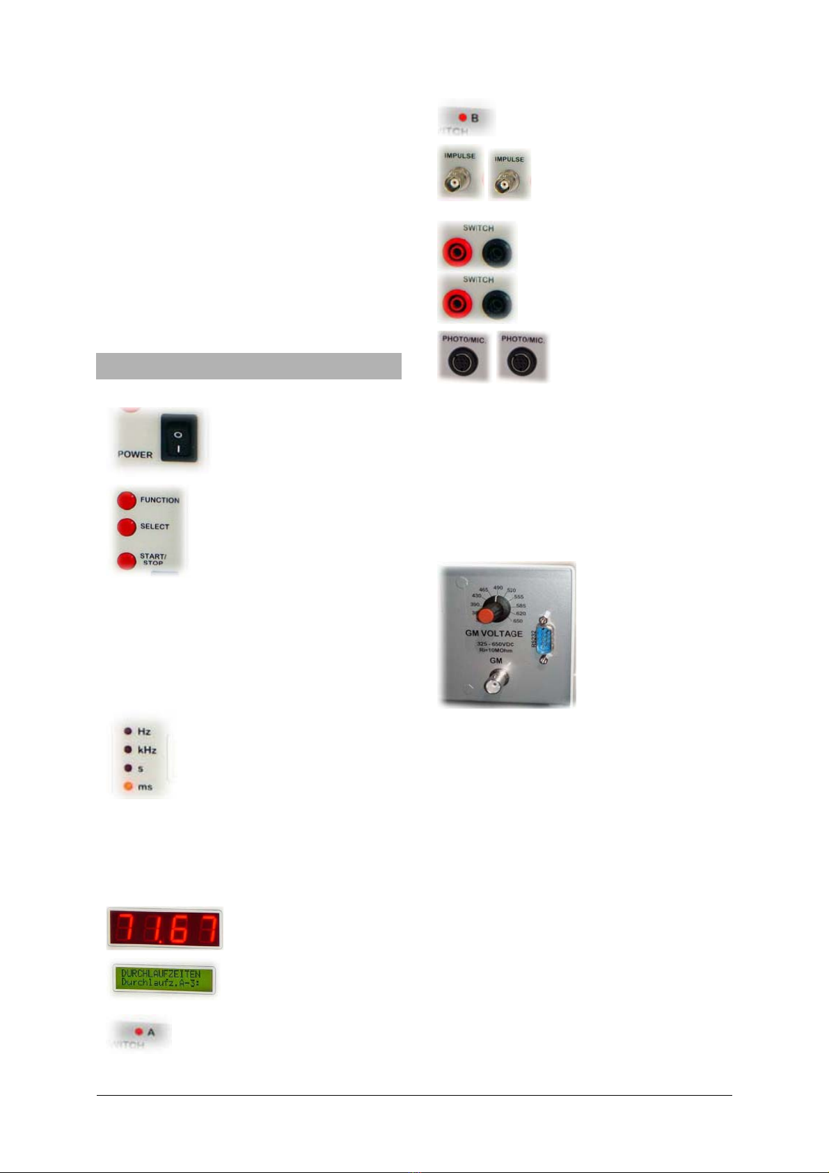
LED ‘Input A’ is lit when the input (the gate) is
open.
Selection of trigger polarity is possible, if pendu-
lum is selected.
The frequency is displayed in Hz or kHz.
5.2 Period measurement
•Select frequency measuring with the push-
button ‘FUNCTION’ and hereafter the wan-
ted measuring function with the push-button
‘SELECT’.
•Press the button ‘START/STOP’ to start the
frequency measurement.
If the measuring function ‘Single measuring’ or
‘Pendulum Single ‘ (pendulum), has been se-
lected, a new period measurement is made,
every time the push-button ‘START/STOP’ is
pressed.
Selection of trigger polarity is possible, if pendu-
lum is selected.
LED ‘Input A’ is lit when the input (the gate) is
open.
The period time is displayed in s or ms.
5.3 Impulse counting
•Select frequency measuring with the push-
button ‘FUNCTION’ and hereafter the wan-
ted measuring function with the push-button
‘SELECT’.
At all counting functions, the ‘Input A’-LED is lit
when counting.
If ‘Continuous’ has been selected, the counter is
started when ‘START/STOP’ is pressed. The
counter can be stopped and restarted (without
resetting the counter) by pressing the
‘START/STOP’.
If the counter has to be reset (count set to zero):
push ‘START/STOP’ to stop the counting, and
thereafter push ‘FUNCTION’ to reset and pre-
pare the counter for a new counting.
If count time has been selected to 1, 6, 10 or 60
seconds, a new counting time is started by
pressing ‘START/STOP’. The counter can not
be restarted if a count is in progress.
If ‘Count. 10s-Hold 5s’ has been selected, the
counter is started when ‘START/STOP’ is pres-
sed. Counting is done in segments of 10 sec-
onds with a 5 seconds’ interval pause. The
counter is reset before each 10 seconds’ count-
ing. The function is stopped when ‘FUNCTION’
is pressed, and the counter is then reset and
prepared for a new measurement.
If ‘10s Continuous’ has been selected, the
counter is started when ‘START/STOP’ is pres-
sed. The counting sequence is continuous, with
10 seconds’ counting followed by a 5 seconds’
displaylock (for reading the result). The counter
is reset (and restarted) every 10 seconds, even
if the display is locked (the counter is still count-
ing). The function is stopped when ‘FUNCTION’
is pressed, and the counter is reset and pre-
pared for a new measurement.
5.4 Start A - Stop B
•The function is selected with the push-button
‘FUNCTION’, and started when
‘START/STOP’ is pressed.
The time measurement starts when an impulse
occurs at input A, and stops when an impulse
occurs at input B. The time is displayed in s or
ms.
The positive- or negative-going triggering is
setup by pressing ‘SELECT’ and ‘FUNCTION’
simultaneously. The current state of the setup is
shown in the display i.e.
Pressing ‘SELECT’ shifts through the four dif-
ferent combinations. When satisfied, press
‘START/STOP’ and the setup is stored in the
internal Lithium Battery backup-memory.
The LEDs ‘Input A’ and ‘Input B’ are lit until an
impulse has occurred at each input. When the
measurement is stopped, a new measurement
is prepared when ‘START/STOP’ is pressed.
The function is aborted if ‘FUNCTION’ is
pressed again, and the counter is reset and
prepared for a new measurement.
5.5 Pass times A and B
•The function is selected with the push-button
‘FUNCTION’, and started when
‘START/STOP’ is pressed.
The positive- or negative-going triggering is
setup by pressing ‘SELECT’ and ‘FUNCTION’
simultaneously. The current state of the setup is
shown in the display i.e.
Pressing ‘SELECT’ shifts through the four dif-
ferent combinations. When satisfied, press
‘START/STOP’ and the setup is stored in the
internal Lithium Battery backup-memory.
The LEDs ‘Input A’ and ‘Input B’ are lit.
The pass times on ‘Input A’ and ‘Input B’ are
measured independent from each other. During
passage of A and B, the light emitting diode at
‘Input A’ or ‘Input B’ is turned off.