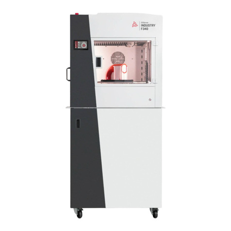
3DGence INDUSTRY F340 User manual

USER MANUAL
3DGence INDUSTRY
F340

2 | 3DGence INDUSTRY F340

3DGence INDUSTRY F340 | 3
version 1.0/07.2017
I INTRODUCTION
1. Introductory comments
2. Printing materials
3. Warning signs
3.1. Auxiliary symbols used in this manual
4. Safety precautions
4.1. General information
4.2. Carrying the device
4.3. Choosing the right site for installation
4.3.1. Connection specications
4.4. Prior to startup
II DEVICE DESCRIPTION
1. Printer construction
1.1. Outline
1.2. Kinematic system
1.3. Printing bed
1.4. Filament chamber
1.4.1. Filament chamber temperature adjustment
1.5. Extruder chamber
1.6. Dual-head module
1.7. Power supply management
1.7.1. Master switch
1.7.2. Printer power switch
1.7.3. Emergency stop button
1.8. Memory card
1.9. Smart Material Manager System
2. Set composition
3. User interface
3.1. Standby menu
3.2. Menu during operation
4. Menu structure
III PREPARING TO OPERATION
1. Installing 3DGence Slicer
1.1. Updating rmware
2. Connectingand turning the printer on
3. Preparing the operating platform
3.1. Calibrating the working area
4. Handling the material
4.1. Installing the material
4.1.1. Material installation is unsuccessful
4.2. Removing the material
6
6
6
7
8
8
8
9
11
12
12
13
13
13
20
20
21
21
22
22
23
23
23
24
25
25
25
25
26
36
38
44
44
44
44
46
46
47
47
49
49

4 | 3DGence INDUSTRY F340
IV OPERATING THE DEVICE (FIRST PRINT)
1. Running a preset code from a memory card
2. Assessing the quality of operation
3. Removing printed models
4. Smart Material Manager
4.1. Material change during printing
5. Cleaning
5.1. Cleaning hotends
5.2. Cleaning heatbed
6. Sleep mode
7. Turning off
V SOFTWARE
1. Introduction
1.1. Quality quarantee
2. Installation
3. Quick start
4. Main software interface
4.1. Model control buttons
4.2. Status bar
4.3. Undo button
4.4. Virtual workspace of the machine
4.5. Print prole selection buttons
4.6. Loaded model
4.7. Virtual buildplate of the machine
4.8. Arrow indicating the physical front of the machine
4.9. Printer axis preview
4.10. Prepare to print button
5. Preview mode of .gcode
5.1. View options
5.2. Options for previewing layers
5.3. Undo button
5.4. .gcode le preview
5.5. Status bar
5.6. File saving button
6. Advanced settings
6.1. Access to advanced settings
6.2. Setting edition window
6.3. Prole sharing
6.4. Advanced proles step-by-step
7. Support and updates
7.1. Support
7.2. Updating print proles
7.3. Software updates
7.4. Update statuses
50
50
50
52
53
53
54
54
54
55
55
56
56
56
56
57
58
58
61
61
61
61
64
65
65
65
65
65
66
66
66
66
66
66
67
67
68
68
69
71
71
72
72
72

3DGence INDUSTRY F340 | 5
version 1.0/07.2017
VI DUAL-HEAD MODULE
1. Module detailed description
2. Unit installation and replacement
2.1. Installing the module
2.2. Module exchange
VII ADDITIONAL INFORMATION
1. Autocalibration and autocompensation
VIII MAINTENANCE
1. Indications for calibrating the heatbed
2. Dual-head module calibration
2.1. Precision axes alignment
2.2. X, Y calibration, dual-head module offset
3. System errors and troubleshooting
IX GLOSSARY
73
73
74
75
75
76
76
77
77
77
77
79
81
83

6 | 3DGence INDUSTRY F340
I INTRODUCTION
1. INTRODUCTORY COMMENTS
2. PRINTING MATERIALS
The FFF (Fused Filament Fabrication) technology used by the 3DGence INDUSTRY F340 printer consists in applying plas-
ticized material layer by layer. This plastic material is a consumable of the printer. It has the form of a plastic lament
(wire, string) of a specic diameter which is wound on a spool (g. 1). 3DGence INDUSTRY F340 uses 1.75 mm diameter
lament only.
Fig. 1. Material spool.
Thank you for choosing a printer supplied by 3DGence INDUSTRY F340. This manual will provide a clear and legible de-
scription of this professional 3D printer allowing you to obtain optimum performance as well as repeatable, safe and
long-lasting operation. The mission of 3DGence is to offer only top professional devices and solutions.
This manual includes information necessary to ensure correct and safe operation. Prior to using the device, it is neces-
sary to read and understand the whole content of this manual. A supplemental document to this manual is avaiable on
the website.
It is forbidden to use the printer by people who have not read the manual. Any misuse can lead to device damage, body
injuries or even endanger operator’s life.
At the end of this manual you can nd a glossary for terms and concepts related to 3D printing. It will facilitate under-
standing professional terms and will explain some of the notions used in this manual.
Using the 3DGence INDUSTRY F340 printer means that you have fully read and understood the manual and accept its
guidelines and exceptions as well as fully accept warranty terms and conditions. A warranty card is attached to the
device.

3DGence INDUSTRY F340 | 7
version 1.0/07.2017
The 3DGence INDUSTRY F340 printer is equipped with two extruders and two printing heads. It makes possible to use two
materials in a single printed model. This solution allows for:
• printing two-colored models,
• printing functional models combining the features of two specic materials in a desired way,
• printing geometrically complex models requiring soluble support structures.
With a wide range of target temperatures, the 3DGence INDUSTRY F340 printer allows for using a wide range of plas-
tics available in a vast palette of colors. Our Certied Material Base has been developed for the INDUSTRY printer and is
available at www.3dgence.com. The base includes a list of all materials supported by the Smart Material Manager (SMM)
system together with typical applications for those materials.
3DGence company recommends using the materials from the Certied Material Base. The materials are supported by the
SMM system making it possible to obtain the most accurate printing performance, automatic material type detection,
and as a result, a top print quality. For more information on SMM system please refer to section 4 Operating the device.
The 3DGence company does not restrict the use of uncertied materials, this however makes it impossible to use the
SMM system.
3DGence takes no responsibility for the quality of prints performed using off-the Base materials, does not take any respon-
sibility for damage caused by utilizing those materials, and provides no support for the quality of prints performed using
laments not listed on the Certied Material Base.
3. WARNING SIGNS
The 3DGence INDUSTRY F340 printer has a number of hazard warning signs. The following sign informs about high tem-
perature utilized in a specic location:
Caution should be exercised when working in zones marked with this sign and it is necessary to wear protective gloves.
Failure to observe the safety rules can result in serious burns.
The INDUSTRY printer is tted with an emergency stop button used to immediately stop its operation. It is red and located
on the top of device housing (g. 2):
Fig. 2. Emergency button location as seen from the front.

8 | 3DGence INDUSTRY F340
4. SAFETY PRECAUTIONS
The information provided below describes the correct operation conditions for the 3DGence INDUSTRY F340 printer. Failure
to observe the indications and contraindications can reduce the printer life, void the warranty or endanger users’ health.
4.1. General information
It is prohibited to install the device:
• in the open, outdoors,
• in damp places or exposed to ooding,
• near volatile or ammable substances,
• in the vicinity of acids, caustic vapors or corrosive substances,
• in places easily accessed by children,
• by using mains power supply without a protective earth (PE) conductor,
• by using mains without a fuse or protected with a fuse of rating current lower than 16A.
It is not allowed to:
• touch the model being printed, printing bed or hotends after printing has started,
• open the operating chamber after printing has started,
• put any parts of the body or objects into the printer operating area – it can result in damage to the device or opera-
tor’s injury,
• touch the hotend with hands, even while wearing protective gloves,
• lean over the heated chamber of the device or open the front door of the device during operation,
• touch live electrical parts,
• touch linear guides or ball screws during device operation,
• operate the device with wet hands,
• put any objects on or under the printer table – both during and out of printer operation,
• put any liquid containers on the device,
• leave the operating device without a supervision of an adult capable of taking appropriate steps in case of failure,
• leave the device operating in the room with children or animals.
DANGER:
The situation or procedure described is potentially hazardous and when improperly handled can result in op-
erator’s injury or damage to the printer. Be careful.
CAUTION:
The situation or procedure described is potentially hazardous and can result in damage to the printer. Use caution.
PROTECTION:
It is necessary to put on the provided gloves in order to carry out the described operation.
3.1. Auxiliary symbols used in this manual:
The whole manual is properly marked with the following signs. Those will allow users to identify actions or situations po-
tentially hazardous to health or the device. It is required to observe recommended rules – failure to observe them can lead
to injuries and damage to the printer not covered by the warranty.

3DGence INDUSTRY F340 | 9
version 1.0/07.2017
It is necessary to:
• use only power supply sources with grounding (to avoid electric shock),
• provide enough free space around the device to open the door to its full extend,
• hold the plug by its casing in order to disconnect the device from the power socket,
• disconnect the device from the mains prior to any repairs or maintenance,
• make sure that mains voltage corresponds to device specications,
• protect the power cord and plug against any damage,
• disconnect the power plug prior to moving the device,
• disconnect the power plug from the mains if the device is to be unused for a longer period of time,
• clean both nozzles periodically removing any external contamination (with a non ammable material),
• always wear protective gloves when operating the printer,
• provide an opportunity to respond quickly in case of failure/unsuccessful print – by providing unobstructed access
to the emergency stop button.
Heated table, hotend and chamber are hot even after printing is completed (g. 3). Check the temperature on the display before
touching those parts, or allow at least 30 minutes after turning off to cool down (e.g in order to clean it, remove the model etc.).
4.2. Carrying the device
To provide users’ safety and to avoid any accidental damage to the device during its carriage observe the following rules:
• prior to moving the device turn it off and disconnect it from the mains,
• the device should be cooled down, and the material and accessories removed from the printer,
• hold the device only by its lifting handles (g. 4-6) and wear protective gloves. Do not hold the device by other parts
while carrying it.
• devices should not be carried by children and older persons due to its considerable weight (140 kg). It is recommend-
ed that the printer is carried by at least 4 people.
Fig. 3. Temperature indications for: 1, 2 – printing head, 3 – working table, 4 – chamber.
1
2
3
4

10 | 3DGence INDUSTRY F340
Fig. 4. Position of lifting handles.
Fig. 5. Position of lifting handles.
handle handle
handle
handlehandle
handle

3DGence INDUSTRY F340 | 11
version 1.0/07.2017
4.3. Choosing the right site for installation
Device installation site should meet the following requirements:
• the device should operate at room temperature,
• the device is not suitable for operating in dusty environments,
• provide a room ventilation adequate to its size,
• the device should be located on a solid, stable ground, capable of long-term bearing of the device work load,
• provide sufcient amount of free space by taking into account device outer dimensions (g. 6 and 7);
provide access from all sides of the printer for maintenance,
• the device should be kept away from other heat sources, direct and long-term exposure to sunlight should
be avoided,
• installation site should be equipped with a mains socket rated 240 V ~ 6A, 50/60 Hz,
• it is recommended to use a UPS to prevent from interrupting printing process in the event of temporary
power failure.
Fig. 6. Maximum dimensions of 3DGence INDUSTRY F340 printer – front view.
Fig. 7. Maximum dimensions of 3DGence INDUSTRY F340 printer – top view.

12 | 3DGence INDUSTRY F340
4.3.1. Connection specications:
A connection suitable for the 3DGence INDUSTRY F340 printer should have the following specications:
Voltage: 230V~
Frequency: 50Hz
Grounded grid with PE, protected with at least a 16A fuse
Maximum power draw: 2700W (2,7kW)
Current: ~11A
4.4. Prior to startup
Prior to each startup make sure that all the following requirements and actions are met:
• check if cables are free from any tears or visible damage. In case of any damage to cables report it to 3DGence
technical support immediately. At the same time it is prohibited to connect the device to the mains and/or make any
repairs on your own,
• check if the lament is dirty, broken, bent or entangled on the spool,
• check if there are any objects or print remains in the printer working area that could cause jamming or damage to
the machine,
• check X and Y axes to verify if nothing obstructs their movements. Check if toothed belts are tensioned and do not
show any visible damage. It can be done through the open printer front door once the device is off and cooled down,
• check if the Z axis stop (g. 8) is not damaged, broken or bent and if it is aligned with the Z axis endstop position (if it
ts into the endstop notch),
• check the correct operation of thermistors (temperature sensors), hotends, chamber and heatbed. To do this start
heating hotends, table and chamber and check if temperature readings on LCD display are increasing. def value
shown on the display indicates a problem,
• directly prior to start make sure that no undesired or dangerous objects are present in the immediate vicinity of the
printer and inside it.
Fig. 8. Stopper and axis Z endstop in correct position.

3DGence INDUSTRY F340 | 13
version 1.0/07.2017
To facilitate the operation of 3DGence INDUSTRY F340 printer and to make reading and understanding the rest of manual
easier, you will nd a number of gures below including the descriptions of the most important device components. Re-
ferring to gures and terms will make it easier to understand the terms used in 3D printing.
1.1. Outline
II DEVICE DESCRIPTION
1. PRINTER CONSTRUCTION
Fig. 9. 3DGence INDUSTRY F340 (front view):
1. Emergency stop button | 2. LCD display | 3. Filament chamber handle
4. Vibroisolator | 5. Chamber’s door | 6. Power button
5
6
1
2
3
4

14 | 3DGence INDUSTRY F340
Fig. 10. 3DGence INDUSTRY F340 (left side view):
7. Emergency stop button | 8. NFC reader | 9. Thermostat display
10. Filament chamber cover handle | 11. Filament chamber’s door
7
8
9
10
11

3DGence INDUSTRY F340 | 15
version 1.0/07.2017
12
14
13
Fig. 11. 3DGence INDUSTRY F340 (rear view):
12. Service cover | 13. Fuse | 14. Power cable slot

16 | 3DGence INDUSTRY F340
Fig. 12. 3DGence INDUSTRY F340 (right view):
15. USB A port | 16. USB B port
15 16

3DGence INDUSTRY F340 | 17
version 1.0/07.2017
Fig. 13. 3DGence INDUSTRY F340 (top view):
17. Filament chamber cover | 18. Heatbed | 19. Dual-head module
20. Rectangular bellows | 21. Working chamber’s doors
17
20
19
18
21

18 | 3DGence INDUSTRY F340
Fig. 14. 3DGence INDUSTRY F340 (izometric view):
22. Filament spool holder | 23. Protective cover
24. SD card slot | 25. Heatbed
22 23
25
24

3DGence INDUSTRY F340 | 19
version 1.0/07.2017
Fig. 15. 3DGence INDUSTRY F340 (front view):
26. SD card slot | 27. LCD display
28. Heatbed | 29. Dual-head module | 30. Power button
27
26
28 29
30

20 | 3DGence INDUSTRY F340
1.2. Kinematic system
The printer works by using Cartesian robot kinematics. The axes described as X and Y move the hotend in horizontal plane,
while Z axis moves the bed in vertical axis. The dimensions of device working space:
X: 260 mm
Y: 340 mm
Z: 340 mm
The printed object cannot exceed those dimensions. The printer software will disable any attempt to generate a le ex-
ceeding the maximum dimensions, however it should be taken into account when designing a printing model.
Fig. 16. Marking of printer axes.
1.3. Printing bed
The entire movable printing bed is marked with a brighter color. Darker color represents the actual printing space. A
heatbed provides a good print adhesion even when the device is operated for dozens of hours with no breaks. The actual
printing bed is installed on a movable mount making it possible to extend it for easier model handling once the printing
is completed.
CAUTION:
Perform all the operations related to print removal, table extension and its re-locking wearing protective
gloves and only when the device is cooled down completely!
Z axis
X axis
Y axis
Other manuals for INDUSTRY F340
2
Table of contents
Other 3DGence 3D Printer manuals

3DGence
3DGence ONE User manual

3DGence
3DGence ONE User manual

3DGence
3DGence DOUBLE P255 User manual

3DGence
3DGence DT3 User manual

3DGence
3DGence DOUBLE P255 Guide

3DGence
3DGence INDUSTRY F340 User manual

3DGence
3DGence ONE User manual

3DGence
3DGence INDUSTRY F420 User manual

3DGence
3DGence INDUSTRY F340 User manual

3DGence
3DGence DOUBLE User manual