3M 4075 Guide

Operations and Instruction Manual
Model #4075
Portable Concrete Anchorage Connector
ANSI Z359.1-07 5,000 lbs / 22kn
OHSA 1910.66 & 1926.502
Effective: 01/2012 Expires: 01/2022 IM-0049 REVA
1. Follow all manufacturer’s instructions.
2. Do not use incompatible connectors.
3. Always inspect your units prior to use.
4. Use the proper method of coupling to anchorage.
5. Remove unit for service if a fall has occurred.
6. Patch all holes with concrete when job is complete.
7. For use by one person only.
8. Pregnant women and minors must not use this product.
9. Designed safe working load is 400 LBS (149.3 kg). Do not
exceed this weight.
10. Not for use with horizontal lifeline systems. Refer to item #4077.
Model #4075 SafeClaw 3/4” anchor is to be used in concrete substrate only.
DO NOT use in steel, wood or any other substrate.
This product is designed for use in cured concrete only and may be pulled in all directions up to 90.
SafeClaw Fall Protection Anchor can be placed in:
* Horizontal surfaces
* Vertical surfaces
* Overhead / ceiling surfaces
*** Warning ***
Do not use incompatible connectors with any SafeClaw Anchor.
Refer to separate instructions supplied with your anchorage connector.
Spoon
End Termination
Bushing Guide
Stop Sleeve Trigger
Spring Swage
Anchor Loop
Heavy Duty Return Wire
3/4” SafeClawAnchorage Connectors
3/4” SafeClaw Fall Protection Anchor
Model - #4075
Designed safe working load: 400 lbs.
Tested - ANSI Z359.1-2007
OSHA - 1910.66 & 1926.502
Strength - 5,000 lbs / 22kn
Color coded in orange tubing
IMPORTANT
All persons using this equipment must read and understand all instructions. Failure to do so may result in serious injury or
death. If a fall occurs, the SafeClaw anchor must be disposed of according to the manufacturer instruction. Users should be
familiar with pertinent regulations governing this equipment. All individuals who use this product must be correctly
instructed on how to use this device.

2
APPLICATIONS
USE: The SafeClaw anchorage connector is designed for fall protection, life line systems, restraint, work
positioning, tie back anchors, and rescue.
REQUIREMENTS
Follow all manufacturer’s instructions with this device. Only trained personnel should install,
maintain, inspect and use this product and its components or other personal protective
equipment in conjunction with this product.
Do not use this device if its components are damaged, cracked, broken or have any deformation to
its structure. Do not use device if it does not operate smoothly or freely.
OSHA requires that any personal fall arrest system be removed from service if a fall has occurred.
This product is not designed to be repaired or altered in any way. The unit must be removed from
service.
Use only compatible connectors with this device. Use only self-locking snap hooks or carabiners
meeting a minimum requirement of ANSI Z359.1-99. Only use connectors that are designed for each
application. Ensure that all connectors are fully closed and in the locked position. Connectors
strength must meet the 5,000 lb requirement.
All personal fall arrest systems must meet all applicable state, federal, city, OSHA and ANSI
requirements and any other regulating government body. It is the responsibility of the employer to
regulate its worker and make sure all laws are being complied with concerning this device.
This anchorage point attachment must be identified by a qualified or competent person. For fall
arrest, the anchor point must meet the 5,000 lb requirement per single user. It is the responsibility of
the user and employer that the concrete can meet the anchor requirements and the proper
anchoring techniques be used with this device.
This anchor point must be used with care. Determining the proper placement of this device must
take into consideration that in combination with a lanyard the user will not be allowed to free fall
more than 6 feet (1.8 M). Make sure the fall path is clear of obstructions and no swing falls occur.
The structure or substrate that this device is anchored to must meet the capabilities of withstanding
the 5,000 lb static load capacity per person. (5,000 lbs for one person) (10,000 lbs for two person)
Pregnant women and minors must not use this product.
Designed safe working load is 400 LBS (181 kg). Do not exceed this weight.

3
Swing Fall
Swing Fall Obstacle - Danger
Danger: Avoid swing falls
Max fall distance 6’
Obstruction/Deck/Floor/Ground
Do not work above anchorage point
Work Surface
Anchorage connector
Shock absorbing lanyard
2’ clearance
Consider D-ring strength
distance and deceleration
distances from shock absorbers
and make sure you obtain a
minimum 2’ clearance.
Swing fall can occur when the worker is
not directly under the anchorage point.
Avoid a swing fall by working directly
underneath your anchorage point. Swing
falls can jeopardize the clearance required
with retractable, shock absorbing
lanyards and other sub-systems of your
fall protection system. Avoid swing fall at
all circumstances. Swing falls can cause
serous injury or death.

4
GENERAL INSTRUCTIONS AND CARE
Inspection:
Make sure unit is straight and operates smoothly.
Make sure cable is not kinked, frayed or damaged.
Make sure metal components are not damaged.
Make sure the Hole Plug slides freely along main cable.
Make sure the label is affixed to unit and legible.
When reusing a previously drilled hole, always inspect the hole carefully.
Storage and Cleaning:
After each use clean with compressed air.
Store in clean dry environment.
Store in secure area at the end of each work day.
Do not pile objects onto or step on the unit.
Keep unit free of grout, grease, oils and dirt or other contaminates.
Never lend your unit to other workers.
Disposal:
Dispose of unit after any fall has occurred.
Dispose of unit if cable becomes kinked or bent.
Proper disposal requires the units main cable to be cut.
Follow all manufacturer’s instructions.
Use only compatible connectors.
Always inspect your units prior to use.
Use the proper method of coupling to anchorage.
Remove unit from service if a fall has occurred.
Patch all holes with concrete when job is complete.
For use by Single User only.
Pregnant women and minors must not use this product.
Designed safe working load is 400 LBS (181 kg). Do not exceed this weight.
Important Warnings
This product is to be used by trained fall protection personnel only. It is to be anchored in accordance with
manufacturer’s requirements. All persons using this equipment must read and understand all instructions.
Failure to do so may result in serious injury or death. If a fall occurs, the SafeClaw must be disposed of according
to the manufacturer instructions. Users should be familiar with regulations governing this equipment. All
individuals who use this product must be properly trained before using this device.
Use only compatible connectors with any SafeClaw . Refer to separate instructions supplied with your connecting
device.
Keep unit free of grout, grease, oils, dirt or other contaminates. This could effect the performance of the unit.

5
This product is to be used by qualified fall protection personnel only. It is to be anchored in accordance with manufacturer’s
requirements in concrete substrate only. Do not anchor in uncured/wet concrete.
The SafeClaw model #4075 is color coded in ORANGE TUBING, and is to be used for FALL PROTECTION ONLY. This unit
is not to be used in any other anchoring situation. Concrete must have a compressive strength of at least 3,000 PSI (20.7MPa)
DO NOT drill anchor hole less then
6” from any corner.
If a hole is 6” from an edge or corner the concrete
substrate must be 12” thick and 12” wide
(example - a 12” x 12” column)
If a hole is 8” from an edge or corner the concrete
substrate must be 10” thick and 16” wide
(example - a 10” x 16” column)
If a hole is 10” from an edge or corner the concrete
substrate must be 8” thick and 20” wide
(example – a 8” x 20” column)
If a hole is 12” or more from any corner or edge the
concrete substrate must be 5” thick.
Drilling for Fall Protection
It is important that you drill your SafeClaw anchor hole to the manufacturer’s required depth
and hole structure. All holes must be 3/4” in diameter and drilled at least 3” into the substrate.
The bored hole walls must be straight and parallel. NOTE: The bored hole must be of uniform
diameter and free of peaks and valleys on the inner wall surfaces. Only use quality industrial
grade rotary hammers and rotary hammer drill bits.
NEVER USE A BENT DRILL BIT!!
Drill a straight 3/4” diameter hole at least 3” deep into your substrate utilizing a rotary hammer
drill that uses industrial grade SDS bits.
Only use industrial grade rotary hammer drills and drill bits.
DO NOT USE masonry drill bits
Drill a 3/4” diameter hole at least 3” deep.
Blow hole clean with compressed air.
Drill hole straight into substrate.
When reusing a previously drilled hole always inspect the hole
carefully to ensure adequate integrity.
Insert unit 3 inches deep into hole.
Set the unit with a slight tug on the anchor loop.
The Stop Sleeve must always be partially inserted into the hole.
Always inspect a previously drilled hole for deformation. Drill
another proper hole if needed.
Inspect the unit for damage each time you use it. If damage has
occurred, dispose of unit.
Never rely on a unit placed by unqualified workers.
Remove your unit at the end of each day.
Never leave a unit inserted in a hole overnight.
Never drill hole closer than 6” to any edge or corner.

6
Inspection:
1. Make sure unit is straight and operates smoothly.
2. Make sure the label is affixed to unit.
3. Make sure trigger stop is not bent or damaged.
4. Make sure cables are not kinked, frayed or damaged.
5. Make sure metal components are not damaged.
6. Make sure metal spoons and conical end fitting operate smoothly
and no metal burrs have occurred.
7. When reusing a previously drilled hole, always inspect the
hole carefully.
Storage and Cleaning:
1. Blow off unit after each use with compressed air.
2. Store in clean dry environment.
3. Store in secure locked area.
4. Store and put away at the end of each day’s work.
5. Do not pile any objects on top of unit during storage.
6. Keep unit free of grease, oils and dirt.
7. Avoid lending your unit to other workers.
Disposal:
1. Dispose of unit after any fall has occurred.
2. Dispose of unit if cable becomes kinked or bent.
3. Dispose of unit if trigger stop is bent or damaged.
4. Dispose of unit if trigger action is rough or sticky.
5. Dispose of unit if return wire becomes bent or frayed.
6. Proper disposal requires the unit’s spoons be cut off the
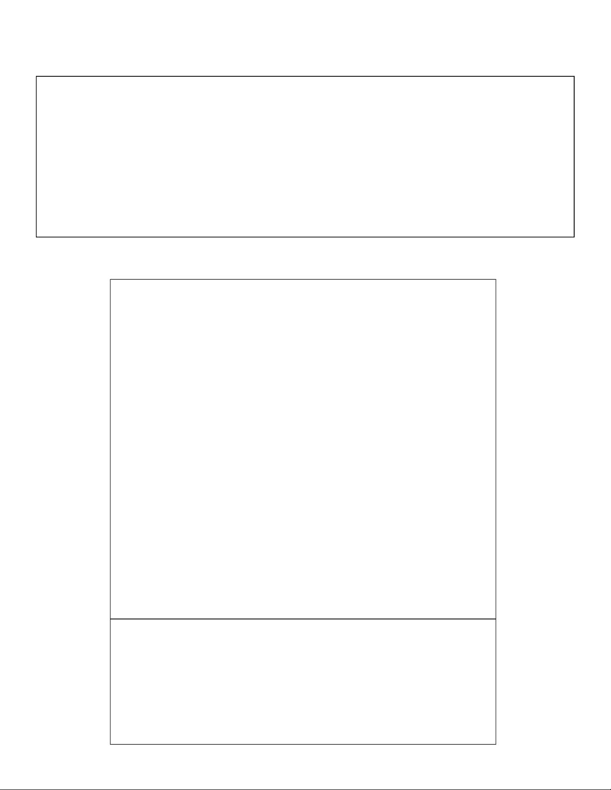
When installing the SafeClaw, place your thumb inside the anchor loop
and your first two fingers around the trigger. Retract the trigger until
the spring bottoms out. With your other hand, pinch the two spoons
between your thumb and index finger. Hold the trigger fully retracted
while inserting the unit into bottom of the hole.
Company Logo
Hole Diameter/Size
Manufactured Date
Batch Number
Model Number
ANSI Z359.1 Mark
Warning Instructions
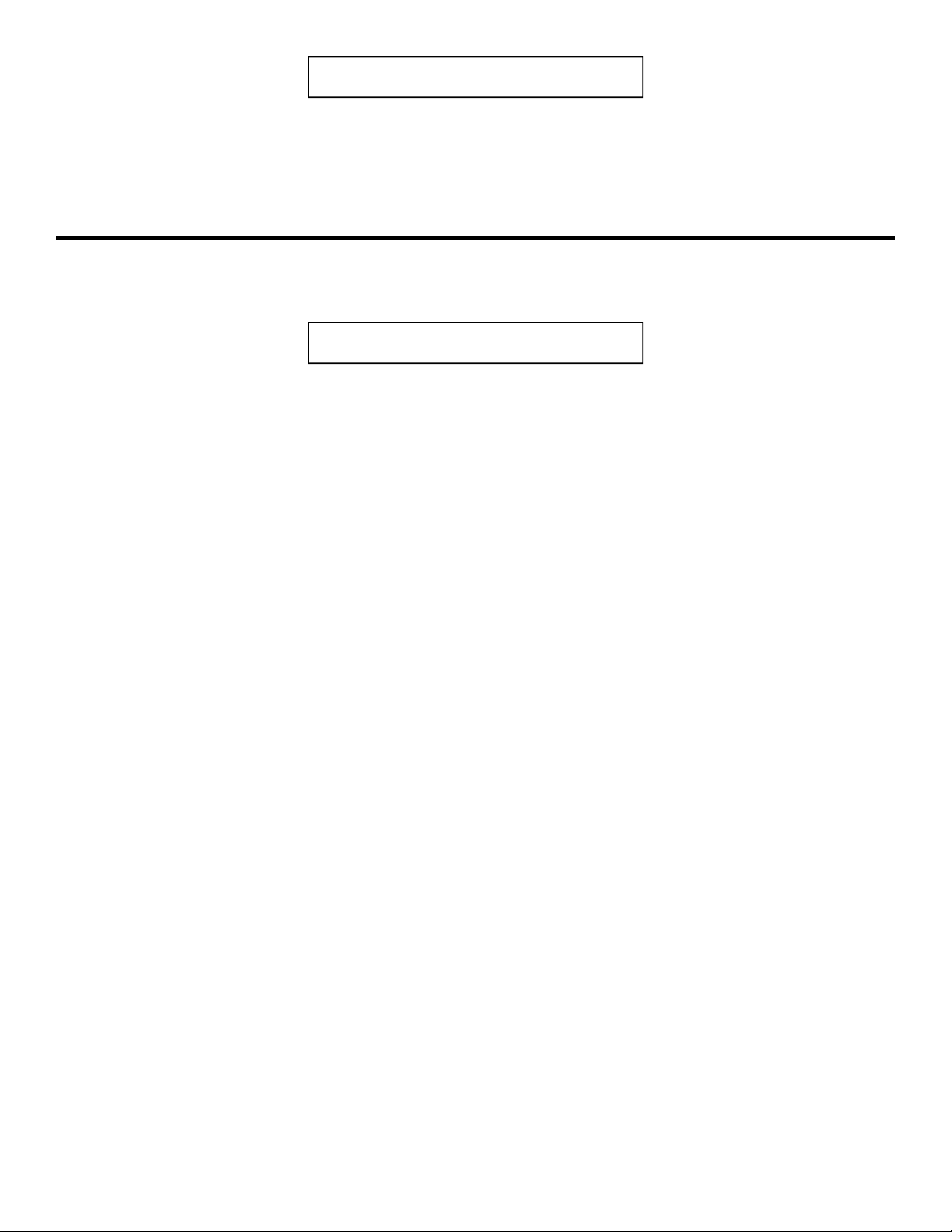
Compliance:
ANSI Z359.1-07 5,000 lbs.
OSHA
1910.66 & 1926.502
Model # 4075 / Batch 000
Manufactured 00/00/00
US Patent 6,729,821
US Patent 7,011,281
US Patent 7,357,363
3/4”
Warning:
All persons using this
equipment must read,
understand and follow all
instructions. Failure to do
so may result in serious
injury or death.
WARNING DO NOT use in
wet or uncured concrete.
Use in normal weight
concrete with a compression
strength at least 3,000 PSI
(20.7 MPa) Use for Fall
Protection Only
Patent Markings
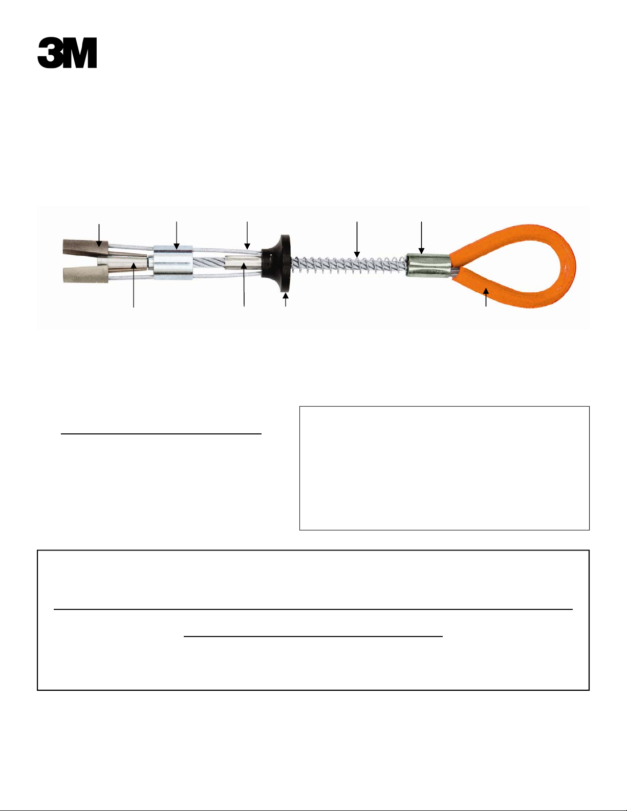
Main Cable 7x19 Aircraft Cable
End Termination 304 Stainless Steel
Spoons 304 Stainless Steel
Bushing Guide 304 Stainless Steel
Stop sleeve 304 Stainless Steel
Trigger 6061 T-6 Aluminum
Spring Zinc Coated Spring Steel
Swage Zinc Coated Copper
Return Wire 1x19 Aircraft Cable
Plastics Polyurethane
If a SafeClaw becomes stuck, insert a punch, screwdriver
or pointed object into the hole until the tip rests on the
striker plate Give a LIGHT, blunt tap with a hammer or
suitable object. The Striker Plate will be easily visible at
the edge of the hole.
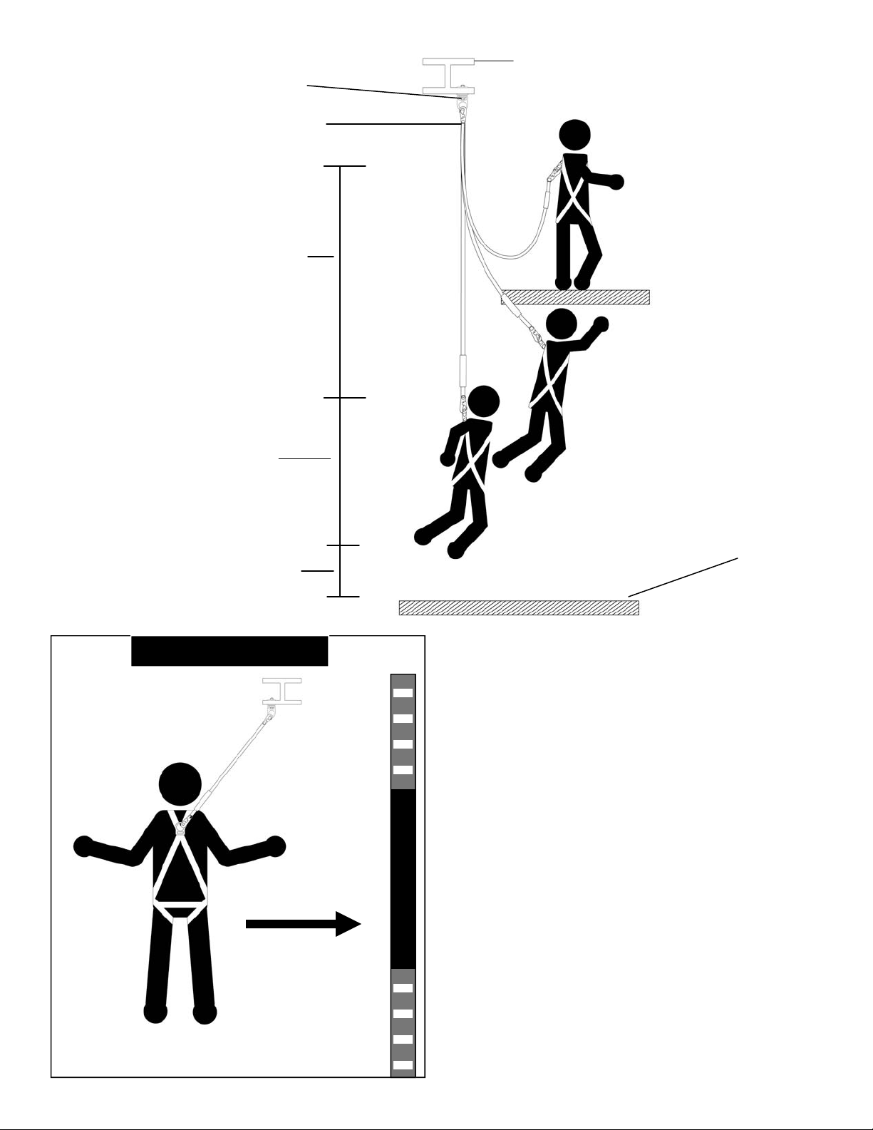
SafeClaw Anchor inserted
into a 3” hole
The metal Stop Sleeve
must be inserted half
way into the hole.
1-800-560-1094
SafeClaw
Reference #
70071532330

7
Date Pass Fail Corrective Action Name of Inspector Signature
INSPECTION AND MAINTAINANCE LOG
DATE PURCHASED: ________________________________________________________
DATE OF MANUFACTURE: _________________________________________________
MODEL NUMBER: _________________________________________________________
3M Occupational Health & Environmental
Safety Division
3M Center Building 235-2W-70
Saint Paul, MN 55144-1000
USA
Technical Assistance: 1-800-243-4630 in U.S.
and 1-800-267-4414 in Canada
www.3M.com/FallProtection
www.3M.com/PPESafety
Table of contents
Other 3M Cables And Connectors manuals
Popular Cables And Connectors manuals by other brands

Goobay
Goobay 58482 user manual

Tecnosystemi
Tecnosystemi smart clima SCC300008 user manual

Masimo
Masimo LNCS LNC Series Directions for use

Austere
Austere Audio Cable Series user guide

Rehab
Rehab 62733-5 User manual & assembly instructions

Crestron
Crestron DigitalMedia Connectors DM-CONN-20 Installation and operation