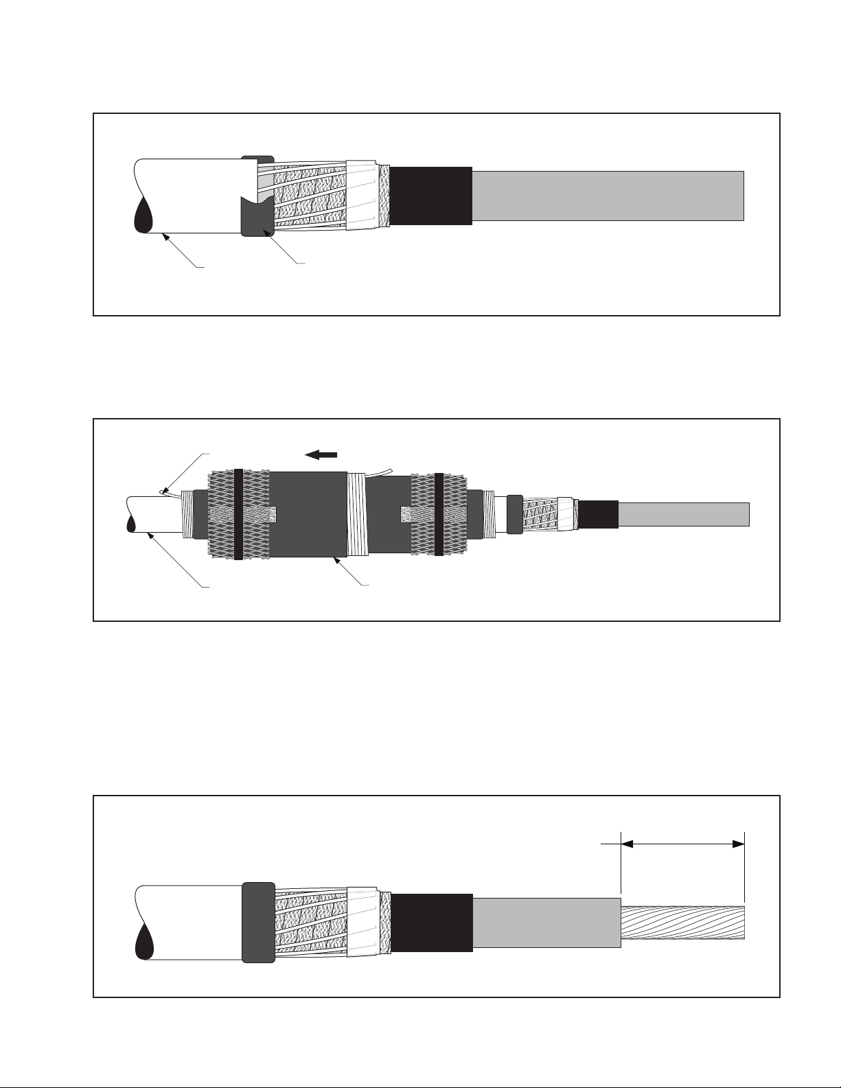
manuals.online logo
Brands
  1. Home
  2. •
  3. Brands
  4. •
  5. 3M
  6. •
  7. Cables And Connectors
  8. •
  9. 3M 5458A-IJ User manual

3M 5458A-IJ User manual

Other 3M Cables And Connectors manuals

3M 8832-JG1 UPC SM User manual

3M

3M 8832-JG1 UPC SM User manual

3M 103 12R1-00 Series User manual

3M

3M 103 12R1-00 Series User manual

3M Cold Shrink QS-III Splicing Kit User manual

3M

3M Cold Shrink QS-III Splicing Kit User manual

3M 3104 User manual

3M

3M 3104 User manual

3M Cold Shrink QT-III 7620-S-INV-3G Series User manual

3M

3M Cold Shrink QT-III 7620-S-INV-3G Series User manual

3M VF-45 User manual

3M

3M VF-45 User manual

3M 36110-3000 Series User manual

3M

3M 36110-3000 Series User manual

3M SafeLok Anchorage 4011 Guide

3M

3M SafeLok Anchorage 4011 Guide

3M 45116 Manual

3M

3M 45116 Manual

3M 7620-S-2 User manual

3M

3M 7620-S-2 User manual

3M ECAM-20 MM-D User manual

3M

3M ECAM-20 MM-D User manual

3M 3443-107N Assembly instructions

3M

3M 3443-107N Assembly instructions

3M 5811 Series User manual

3M

3M 5811 Series User manual

3M 5415A-IJ User manual

3M

3M 5415A-IJ User manual

3M Litmann Quality 3100 User manual

3M

3M Litmann Quality 3100 User manual

3M 8865-C User manual

3M

3M 8865-C User manual

3M 4604GW User manual

3M

3M 4604GW User manual

3M 8800-APC/AS/AGC User manual

3M

3M 8800-APC/AS/AGC User manual

3M 4075 Guide

3M

3M 4075 Guide

3M 10350-1230 User manual

3M

3M 10350-1230 User manual

3M 3443-112 Assembly instructions

3M

3M 3443-112 Assembly instructions

3M 8250 Assembly instructions

3M

3M 8250 Assembly instructions

3M QCI Series User manual

3M

3M QCI Series User manual

3M 5810 Series User manual

3M

3M 5810 Series User manual

Popular Cables And Connectors manuals by other brands

StarTech.com ST124HD20 quick start guide

StarTech.com

StarTech.com ST124HD20 quick start guide

Philips SWV4543S/10 Features

Philips

Philips SWV4543S/10 Features

Larson Electronics 10-50C instruction manual

Larson Electronics

Larson Electronics 10-50C instruction manual

Grip MEK-PM Assembly and operating manual

Grip

Grip MEK-PM Assembly and operating manual

Ultra Products Travel Pack #3 ULT31436 Specifications

Ultra Products

Ultra Products Travel Pack #3 ULT31436 Specifications

Surpass QCH-F Operation manual

Surpass

Surpass QCH-F Operation manual

Philips SWA6310 Specifications

Philips

Philips SWA6310 Specifications

StarTech.com CRJ4550PK quick start guide

StarTech.com

StarTech.com CRJ4550PK quick start guide

Nohau EMUL-IP2K-PC user guide

Nohau

Nohau EMUL-IP2K-PC user guide

Foxun SX-SP144E-HD4K2K operating instructions

Foxun

Foxun SX-SP144E-HD4K2K operating instructions

Philips SWA3305W Specifications

Philips

Philips SWA3305W Specifications

opticis Stretch DVIM1-1P0x user manual

opticis

opticis Stretch DVIM1-1P0x user manual

Volkswagen VAS 6558A operating manual

Volkswagen

Volkswagen VAS 6558A operating manual

NEXIBO N-13 user manual

NEXIBO

NEXIBO N-13 user manual

CYP PU-1H3HBTL Operation manual

CYP

CYP PU-1H3HBTL Operation manual

Allen-Bradley 1784-u2dhp installation instructions

Allen-Bradley

Allen-Bradley 1784-u2dhp installation instructions

Global Caché Flex Link Blaster quick start

Global Caché

Global Caché Flex Link Blaster quick start

Hauppauge USB-Live2 Quick installation guide

Hauppauge

Hauppauge USB-Live2 Quick installation guide

manuals.online logo
manuals.online logoBrands
  • About & Mission
  • Contact us
  • Privacy Policy
  • Terms and Conditions

Copyright 2025 Manuals.Online. All Rights Reserved.

3M™ Cold Shrink Integrated Splice
Kit QS-III 5458A-IJ
for Jacketed Concentric Neutral (JCN) Cable
Instructions
IEEE Std. 404
25/28 kV Class
200 kV BIL
 CAUTION
Working around energized systems may cause serious injury or death. Installation should
be performed by personnel familiar with good safety practice in handling electrical
equipment. De-energize and ground all electrical systems before installing product.
KitSelectionTable
Kit Number Cable Insulation O.D. Range Conductor Size Range
5458A-IJ 1.24"–2.07"
(31,5–52,6 mm)
500–1000 kcmil*
(240–500 mm2)
* Splices (including size transitions) can be made to smaller or larger conductors (but larger conductors may require special neutral
handling), provided both cables are within the Insulation O.D. Range and the connector meets the dimensional requirements
shownbelow.
ConnectorDimensionalRequirements
Minimum Inches (mm) Maximum Inches (mm)
Outside Diameter 1.05" (26,7 mm) 2.07" (52,6 mm)
Length
Aluminum (Al/Cu) Compression —7.50" (191 mm)
Length
Copper Compression and
3M™ Shearbolt Connector QCI 500-1000
—8.25" (210 mm)
September2010
78-8127-8872-3-B3
 2 78-8127-8872-3-B
1.0 Kit Contents
a. 3M™ColdShrinkIntegratedSpliceBody5458A-IJ(1ea.)
b. ConstantForceSprings(4ea.)
c. RedCompoundTubes(non-siliconegrease)(2ea.)
d. Scotch®RubberMasticTape2228Rolls,2"x48"(2ea.)
e. Scotch®MasticSealingStrips2230,6"length(8ea.)
f. ColdShrinkAdapterTube(1ea.*)
g. 3M™CableCleaningPadsCC-3(1ea.)
h. Scotch®ElectricalShieldingTape24,1"x15'(1ea.)
i. 3M™AluminumFoilTapeStrips1115B,10"length(2ea.)
j. Cut-backTemplate(2ea.**)
k. InstructionBooklet(1ea.)
*Cold shrink adapter tube may not be included in all kits.
**Kits contain either 1 or 2 cut-back templates as needed per conductor size.
Note: Do not use knives to open plastic bags.
Note: Connector not shown, but if included, it is indicated on the packaging label.
78-8127-8872-3-B 3
2.0 Prepare Cables
2.1 Checktobesurethecablefitswithinthekitrangesasshownonthecoverpage.
2.2 Preparecablesaccordingtostandardprocedures.Refertotemplateprovidedorillustrationbelowforproper
dimensions(Figure1).
“A”
“B”
3 1/2"
(89 mm)
Insulation
Semi-Con
Neutral Wires
Cable Jacket
Typical Conductor Size*
kcmil (mm2)
Insulation OD Range
Inches (mm)
Jacket Cutback "A"
Inches (mm)
Semi-con Cutback "B"
Inches (mm)
500**-750
(240-400)
1.24–1.70
(31,5–43,2)
15 3/4
(400)
9 1/4
(235)
1000**
(500)
1.59–2.07
(40,4–52,6)
15 1/4
(387 mm)
8 3/4
(222)
*For 100% and 133% insulation levels, Insulation OD is the final determining factor.
**Cables must be within the Insulation OD Range of the splice kit and the connector must meet the dimensional requirements shown on the front page.
Figure1
2.3 Carefullybendthecutneutralwiresupandawayfromthecablesemi-conasshown.FoldoneScotch®Mastic
SealingStrip2230inhalflengthwiseandapplyonewraponlyatcablejacketedgeundertheneutralwires
(Figure2).
Insulation
Semi-Con
Neutral Wires
Scotch® Mastic Sealing Strip 2230
Fold mastic strip in half lengthwise
Figure2
 4 78-8127-8872-3-B
2.4 Markthecablesemi-con4"(102mm)fromthecablejacketedge.Applytwohalf-lappedlayersofScotch®
ElectricalShieldingTape24overthecablesemi-con,startingfromthemasticedgeouttothemarkonthe
semi-conandback.Half-hitchtotieoff(Figure3).
Insulation
Semi-Con
Neutral Wires
Scotch® Mastic Sealing Strip 2230
4"
(102 mm)
Scotch® Electrical Shielding Tape 24
Figure3
2.5 Carefullylayneutralwiresbackdownontopoftheshieldingtapeandpressintomastic.Keepwireprofilelow
byfollowingtheconcentricturninthecable(Figure4).
2.6 Removethelinerfromone3M™AluminumFoilTapeStrip1115Bandsecuretheendsoftheneutralwires.
Wrapthealuminumtapeontopofitselfandtightlypressdownontheedgeofthetapetowardtheendofthe
electricalshieldingtape(Figure4).
Insulation
Semi-Con
Neutral Wires
3M™ Aluminum Foil Tape Strip 1115B
Scotch® Electrical Shielding Tape 24
Press down edge tightly
Figure4
78-8127-8872-3-B 5
2.7 ApplyaScotch®MasticSealingStrip2230overthepreviouslyappliedmasticstripandoverlappingontothe
cablejacket.Kneadmasticaroundneutralwires.Overwrapmasticwithvinyltape,takingcarenottoextend
tapealongneutralwires(Figure5).
Scotch® Mastic Sealing Strip 2230
Overwrap with vinyl tape
Cable Jacket
Figure5
2.8 Cleanorcovercablejacket30"(760mm)fromjacketedgeonsidewheresplicebodywillbeparked.
2.9 Slideintegratedsplicebodyontocleancablejacket,loosecoreendfirst(Figure6).
Loose core end
Integrated splice body
Cleaned cable jacket
Figure6
3.0 Install Connector
Note: If using a crimp-type connector, go to step (3.3).
3.1 Ifusinga3M™ShearboltConnectorQCI500-1000,refertotheinstructionsincludedwiththeconnectorfor
insulationcut-backdimension.Insulationremovallengthshallnotexceed33/4"(95mm)fromconductorend
(Figure7).
Refer to connector instructions for dimensions
Figure7
 6 78-8127-8872-3-B
3.2 Install3M™ShearboltConnectorQCI500-1000accordingtotheinstructionsincludedwiththeconnector
(Figure8).
Connector
Shearbolt
Figure8
Go to section 4.0 “Install Splice.”
3.3 Ifusingacrimptypeconnector,removecableinsulationfor1/2connectorlengthplusanallowance*for
increasesinconnectorlengthduetocrimping.Insulationremovallengthshallnotexceed4-1/8"(105mm)from
conductorend.Donotinstallconnectornow(Figure9).
*Note: This assumes that the installer has determined the increased length of an aluminum connector crimped
with a specific tool and die.
Aluminum (Al/Cu) Crimp Connector Growth Chart
Conductor Size Typical growth allowance (per end)
500 kcmil 1/4" (6 mm)
750–1000 kcmil 3/8" (10 mm)
Note: 1) Copper connectors do not require a length change allowance.
2) Maximum aluminum connector crimped length allowed is 8.25" (210 mm).
One-half connector length
+ growth allowance*
Figure9
78-8127-8872-3-B 7
3.4 For500kcmilcopperconnectors,orconnectorswithanO.D.between1.05–1.24"(26,7–31,5mm):
Parkcoldshrinkadaptertubeoncableinsulation(Figure10).
Cold shrink adapter tube
Figure10
3.5 Installconnector.Seetable(oncover)forproperconnectordimensions.(Forstandard3M™Connectors,refer
totableattheendofthisinstructionforcrimpinginformation).Removeanyexcessoxidationinhibitorfrom
connectorendsifaluminumconnectorisused(Figure11).
Connector
Figure11
4.0 Install Splice
4.1 Applyatapemarkertosemi-coninsulationshieldoncablewhichdoesnotcontainsplice.Measure11-1/2"

(292mm)fromcenterofconnector(Figure12).
Tape Marker
Semi-con
11 1/2"
(292 mm)
Figure12
 8 78-8127-8872-3-B
4.2 Ifusingcoldshrinkadaptertube:Positionadaptertubeovertheconnector.Shrinkadapternearcenterof
connectorbypullingandunwindingtheloosecoreendinacounter-clockwisedirection(Figure13).
Cold shrink adapter tube
Figure13
4.3 Cleancablesusingstandardpractice:
 a.Donotallowsolventorabrasivetocontactthecablesemi-conductiveinsulationshield.
 b.Donotreducecableinsulationdiameterbelow1.24"(31,5mm)specifiedforthesplice.
 c.Theinsulationsurfacemustberound,smoothandfreeofcuts/voids.Sandingmaybenecessary,finish
sandingshouldbedonewitha300gritorhigherelectricalgradeabrasive.
 d.Makecertainthatthecableinsulationissmooth,cleananddrybeforecontinuing.
4.4 Applyredcompoundoncableinsulations,makingcertaintofillinedgeofcablesemi-con.Donotuse
siliconegrease(Figure14).
Apply Red
Compound
Apply Red
Compound
Fill semi-con step Fill semi-con step
Figure14
78-8127-8872-3-B 9
4.5 Positionthesplicebodyoverconnectorarea,aligningendofthesplicebody(notthecore)atthecenter
ofthetapemarker.Slowlystarttoremovethesplicecorebypullingandunwindingtheloosecoreend
counterclockwise,allowingonly¼"(6mm)ofthesplicetoshrinkontothetapemarker.Carefullyslidethe
splicebodyoffthetapemarkerbypullingandtwistinguntiltheentiretapemarkerisexposed.Continue
removingthecoretocompletethesplicebodyinstallation(Figure15).
Note: The splice body ends must overlap onto the semi-con of each cable by at least 1/2" (13 mm).
Note: Do not push the splice body toward the tape marker as this may cause the end to roll under. If the end
does roll under, DO NOT use sharp-edged tools to pull it out as this could cut and damage the splice.
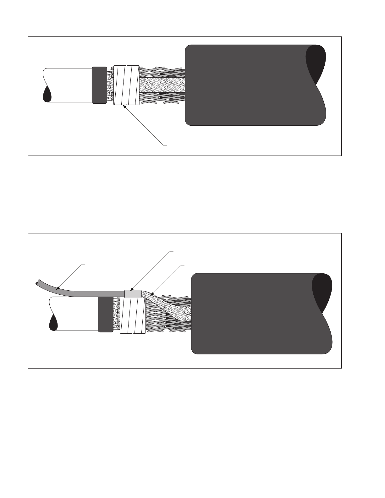
Unwind Counter-clockwise
Align splice body with tape marker
Figure15
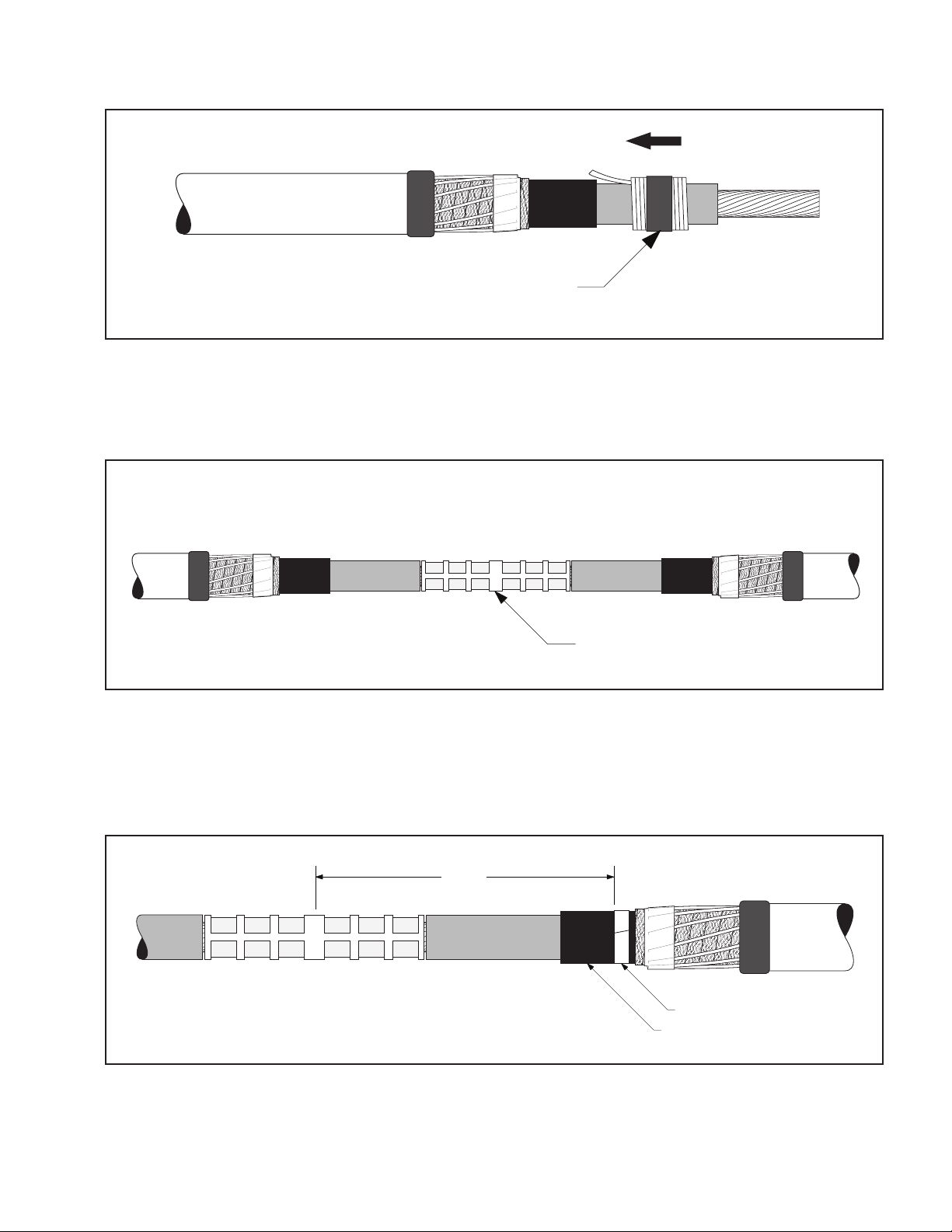
5.0 Connect Shielding
5.1 Removethevinyltapeholdingtheshieldsleeveontherejacketingtube,andspreadtheshieldsleeveouttoward
thecablejacket.
Note: The 3M™ Cold Shrink Integrated Splice Body includes a pre-installed ground braid for external
grounding on either side of the splice body. If not using the ground braid, it may be tied into the ground
system with the shield sleeve using constant force springs as shown below.
5.2 Hand-tightentheshieldsleeveoutwardandsecureit(alongwiththegroundbraidifnotgroundingexternally)
totheneutralwiresoneithersideofthespliceusingtwoconstantforcespringsoneachendbetweenthe
vinlytapeatthejacketedgeandthealuminumfoiltapeasshown.Trimexcessgroundbraidifneeded.Cinch
(tighten)thespringafterwrappingthefinalwinding(Figure16).
Ground Braid
Aluminum Foil Tape beneath Shield Sleeve
Constant Force Springs
Cable Jacket
Rejacketing Tube
Vinyl Tape
Figure16
 10 78-8127-8872-3-B
5.3 Wraptwohalf-lappedlayersofvinyltapeovertheconstantforcesprings(Figure17).
Vinyl Tape
Figure17
6.0 External Grounding (Optional)
Note: Use these instructions if circuit grounding is required at this location.
6.1 Connectagroundwiretothepre-installedgroundbraidontheintegratedspliceusinganappropriateconnector.
Keepconnectorprofileaslowaspossible.ForC-taporH-tapconnectors,positionflatagainstthecable.Crimp
connectorfollowingtheconnectormanufacturer’srecommendations(Figure18).
Ground Wire
Connector
Ground Braid
Figure18