3M VF-45 User manual

VF-45™ Fiber Optic Connector
Quick Install Kit
Instructions
January 2004
78-8097-8734-0-D

2
• Cable Jacket Stripper
• Snips
• Buffer Stripper
• Duplex Stripper
• Puck Assembly
• Cotton Swabs
• Lint Free Cloths
• Alcohol Bottle
• Polishing Station
• Lapping Film
• Carrying Case
• Tool Pouch
• Instructions
• Cleaning Wires
• Fiber Microscope (with three adapters and case)
• Removable Cleave Blade
1.0 3M™ VF-45™ Fiber Optic Connector Quick Install Kit Contents
Warning: Do not touch cleave blade. Any material or solvent that contacts the blade can cause damage.

3
2.0 Features
The 3M™ VF-45™ Fiber Optic Connector Quick Install Kit is used to field terminate VF-45 multimode and single
mode sockets. The VF-45 sockets are dual optical fiber connectors that are primarily used in fiber-to-the-desk LAN
applications. The duplex fibers are terminated simultaneously using this tool kit.
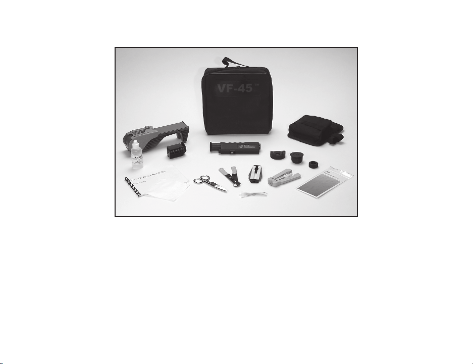
The VF-45 Fiber Optic Connector Quick Install Kit has the following hardware features and benefits:
a) Carrying case for ease of use with compartments for all required tools.
b) Integrated installation tool comprising:
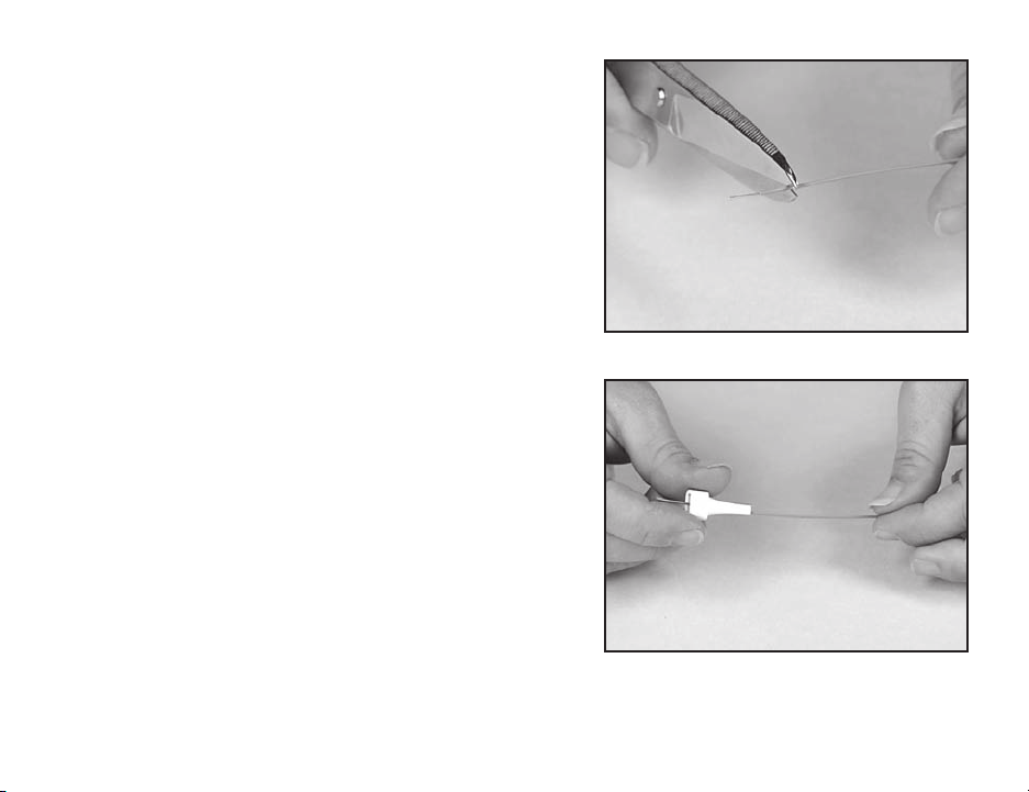
• Easy scribe and break of fibers to prepare for polishing
• Fiber stub catcher
• Slip resistant polishing base
• Tool pouch storage for all hand tools
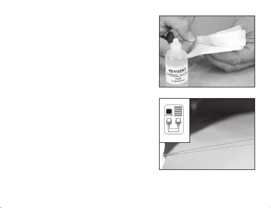
• Adhesive backed lapping film for polishing
• Versatile dual illumination microscope with adapters for inspection of:
1) Polishing puck end-face
2) Patch cord plug-fibers
3) Standard ferruled connectors
c) All fiber measurements made with hand tools (no precise measuring)
d) Easy fiber insertion and socket assembly
e) Audible click verifies socket assembly
f) Cleaning with cotton swab
g) Quick assembly of VF-45 socket
h) Angle polishing for low loss, low reflectance connections
i) Replaceable polishing pad
j) Replaceable scribe assembly
k) Replaceable polishing face
Caution: Wear safety glasses during all work operations.

4
a
cb
d
3.0 3M™ VF-45™ Socket
3.1 Contains the following:
a) Housing c) Boot
b) Socket fiber holder (SFH) d) Base
Note: The VF-45 Socket is sold separately.
4.0 Installation
4.1 Position polishing base.
At the patch panel area, place the polishing base on the
patch panel work tray or on a nearby suitable surface. At
the work area outlet, choose a suitable surface. Open the
hinged scribe cover.
Attach a sheet of lapping film to polishing surface of the
station. Removal of the release liner from lapping film
exposes adhesive backing to secure the lapping film to the
polishing surface.
Tech Tip: Before placement of the lapping film, clean the
polishing surface with a lint free wipe moistened
with isopropyl alcohol. Lapping film will last for
about 50 connectors.
Tech Tip: All Isopropyl Alcohol should be reagent grade, 99%
or better. The use of inferior alcohol will adversely
effect interconnect losses. This can be purchased
from a chemical supply house.

5
Note: Carefully follow safety, health and environmental
information on container label or Material Safety Data
Sheet for isopropyl alcohol being used.
4.2 Position the polishing puck assembly.
Remove the polishing puck assembly from the storage
compartment beneath the polishing pad and place it on
the dovetail on top of the hinged scribe cover.
Open the top of the polishing puck assembly by
unlatching it from the side and opening it by its hinge to
expose the inner cavity.
4.3 Position socket fiber holder in polishing puck
assembly.
Ensure that the cavity is clean of debris and that the face
of the puck is in the up position. Position a socket fiber
holder into the cavity of the polishing puck assembly.
Tech Tip: Do not press on the activation cap of the SFH
during insertion. It should be held by the four
prongs only. (See insert)

6
4.4 Adjust the jacket stripper so they cut only the outer jacket
and not the Kevlar® strands. Move the stop location
with a small, flat-head screwdriver until the hole size is
correct.
4.5 Remove outer cable sheath.
Cut outer cable jacket at a length of 1 meter (39 in.) and
set tool aside.

7
Remove the outer sheath by pulling on the end of the
cable jacket, sliding it off the Kevlar® strands and inner
optical fiber buffer tubes. Do not use the tool to slide the
outer jacket off the inner Kevlar strands and buffer tubes.
Discard the outer jacket.
4.6 Remove Kevlar strands.
Use the snips to cut the Kevlar strands flush with the
cable jacket. Discard the strands.
Use a cable tie to strain relief cable in patch panel or
outlet within 2.5 mm (1 in.) of end of sheath.
Note: Do not over tighten the cable tie around the cable jacket.
Pinched fibers may experience optical power loss.

8
4.7 Even-up the fiber and buffer tube.
If the fiber extends past the buffer tube, trim the
end so the tube and fibers are the same length.
4.8 Position boot.
Place the boot onto the buffer tube, small end
first. Slide the boot along the buffer tube until it
is out of the way.

9
4.9 Remove buffer tube.
Verify that length guide is pushed flush against
back of tool. Insert the buffer tube into the buffer
tube stripper until it bottoms against the tool.
Squeeze the handles of the tool together and
pull the buffer tube off to expose the two 250 µ
optical fibers.
4.10 Strip the buffer coating from the fibers.
Insert both of the 250 µ fibers into the tube guide
of the dual fiber stripper until the buffer tube
is flush with the outer edge of the tube guide.
Squeeze the handles of the dual fiber stripper
together and pull the fibers out.
Note: Clean the stripper blades with the brush end of
the cleaning tool when needed. See “Dual Fiber
Stripper Maintenance” section.

10
orange
blue
4.11 Clean the fibers.
Moisten a section of a lint-free wipe with isopropyl
alcohol. Wipe the residue from the fibers using the
moistened lint-free wipe until the fibers squeak.
Tech Tip: All Isopropyl Alcohol should be reagent grade, 99%
or better. The use of inferior alcohol will adversely
effect interconnect losses. This can be purchased
from a chemical supply house.
Caution: Care should be used when handling fibers so as not
to break them, or to handle them in such a way that
they could penetrate your skin.
Note: Carefully follow safety, health and environmental
information given on container label or Material Safety
Data Sheet for isopropyl alcohol being used.
4.12 Thread the fibers into the holder.
Spread the fibers slightly apart between your fingers
to feed them into the socket fiber holder. Refer to
label inside polishing puck for duplex A-B crossover
orientation. (e.g., patch panel A-to-B, outlet B-to-A).
Every link must cross (i.e. patch panel to patch panel).
Tech Tip: Make sure that the face of the polishing puck
assembly is in the closed position before the fibers
are inserted.

11
Slide the fibers along the fiber guide grooves of the
polishing puck assembly and into the socket fiber holder.
Fiber insertion is complete when the color coded fibers
enter the socket fiber holder and positively stop.
Tech Tip: If resistance is felt when inserting the fibers, back
the fibers out of the SFH and verify that all of the
coating residue has been removed then reinsert. If
resistance continues, it may be necessary to replace
the SFH.
Place the buffer tube into the strain relief foam so that
the two fibers are held with a slight bow in the socket
fiber holder.
Caution: Use care as bare fibers are now protruding through
the face of the polishing puck.
Caution: Care should be used when handling fibers so as not
to break them, or to handle them in such a way that
they could penetrate your skin.

12
4.12 Actuate the fiber holder.
Rotate and close the top section of the polishing puck
assembly by its hinge to actuate the socket fiber holder.
The top section will latch with an audible click when it is
fully closed.
4.13 Scribe and polish fibers.
Open the hinged scribe cover by rotating the polishing
puck assembly along with the dovetail to expose the
scribe area.
Lift the polishing puck assembly off of the dovetail.

13
Place the polishing puck assembly into the scribe
entrance by inserting the exposed fibers into the fiber stub
basin.
Caution: The catch basin of the polishing base should be
emptied often and before storing. Safely dispose of
fibers per your company’s practice. The basin should
only be used for fiber scraps, no other debris should
be inserted.
Tech Tip: Ensure that the polishing face is in the correct
orientation for the scribe motion. Note outline
of puck face in scribe track. Also, care should be
exercised in landing the polishing puck assembly
into the scribe entrance.
4.14 Move the polishing puck assembly smoothly through
the scribe channel. As the puck slides through the scribe
channel, continue the motion all the way across the
lapping film.
Tech Tip: Use caution when sliding puck through scribe
channel. Keep pressure on polishing puck. Do not
lift when going across scribe.

14
With medium pressure, slide the puck back and forth
across the entire length of the lapping film 10–15 times.
Use a different area of the film for each connector to
extend film life.
4.15 Clean the fibers.
Place the polishing puck assembly back onto the dovetail.
Moisten a lint-free wipe with isopropyl alcohol. Wipe the
polishing puck face assembly using the moistened lint-
free wipe.
Note: The puck face should feel completely smooth with
no fiber protrusion whatsoever. If resistance is felt,
continue to polish until the face is smooth.
Tech Tip: All Isopropyl Alcohol should be reagent grade, 99%
or better. The use of inferior alcohol will adversely
effect interconnect losses. This can be purchased
from a chemical supply house.
Tech Tip: This wipe can also be used to clean the lapping film.
Clean after every connector for maximum film use.
Note: Carefully follow safety, health and environmental
information on container label or Material Safety Data
Sheet for isopropyl alcohol being used.
Warning: Do not touch cleave blade. Any material or solvent
that contacts the blade can cause damage.

15
4.16 Inspect the fibers.
Attach the VF-45 puck adapter to the fiber microscope.
DANGER—LASER
DO NOT use the microscope to view active fiber signals under
ANY circumstances. Active fiber signals contain laser light, and
direct eye contact with laser light should be avoided. The failure
to avoid direct eye contact with laser light can result in serious
damage to the eye. The microscope may magnify the laser
light in active fiber signals; direct eye contact with magnified
laser light should be avoided.
Insert the polishing puck into the puck adapter. An
audible click will be heard when the puck is fully seated.
(Note: the adapter is keyed to accept the puck in only one
direction).

16
Press the LED toggle switch to the desired illumination
mode and focus image at the eyepiece.
The microscope will show either coaxial or oblique
lighting views based on the direction of the toggle switch.
Slide the adapter side to side to view each fiber
individually.
coaxial (II) oblique (I)

17
Examine the fiber ends for flaws. Any flaw in core of the fiber is unacceptable.
Coaxial Illumination—UNACCEPTABLE
Coaxial Illumination—ACCEPTABLE
Oblique Illumination—UNACCEPTABLE
Oblique Illumination—ACCEPTABLE

18
4.17 Rotate open the polishing face of the polishing puck
assembly to expose the ends of the fibers. Use a cotton
swab moistened with isopropyl alcohol to clean the fibers.
Clean both fibers by running the applicator along the
length of the two exposed fibers, toward the fiber ends.
Stroke past the ends of the fiber in an outward motion to
make sure the entire shaft of fiber has been cleaned.
Tech Tip: Two strokes of the applicator on each side of the
fiber should be adequate.
Note: Carefully follow safety, health and environmental
information on container label or Material Safety Data
Sheet for isopropyl alcohol being used.

19
4.18 Socket Assembly.
Close the hinge scribe cover and open the polishing puck
assembly top by releasing the latch.
Leave the fiber holder in polishing puck assembly.
Align the “pins” of the housing over the “hinge” of the
fiber holder.
Snap the housing onto the socket fiber holder.
Remove the housing from the polishing puck assembly
(the fiber holder will be attached to the housing).
Make sure the SFH sits flush in the housing.

20
Hold the base and align the base “hinge” over the pins of
the housing. Snap the “hinge” over the “pins.”
Rotate the base on the housing until the housing and base
latch closed with an audible click.
Table of contents
Other 3M Cables And Connectors manuals

3M
3M Liqui-Cel MM 0.5x1 Series Manual

3M
3M Crimplok 8700-PS/APC User manual

3M
3M 8865-C User manual

3M
3M 5321 User manual

3M
3M Cold Shrink QT-III 7620-S-INV-3G Series User manual

3M
3M 3443-112 Assembly instructions

3M
3M 4604GW User manual

3M
3M 36110-3000 Series User manual

3M
3M 8250 Assembly instructions

3M
3M Cold Shrink QS-III Splicing Kit User manual