3M ECAM-20 MM-D User manual

June 2011
78-8140-3820-0-B
3M™External Cable Assembly Module (ECAM)
Double Cable Entry Port
ECAM-20 MM-D
Instructions
3

278-8140-3820-0-B
1.0 General
The 3M™External Cable Assembly Module (ECAM) Double Cable Entry Port ECAM-20 mm-D is designed to
accept fiber optic loose buffer tube & central tube ribbon type cables with external diameters of up to
20 mm /0.78". The kit will accommodate cables with single or dual cable strength members (CSM).
2.0 Kit Contents
2.1 For all loose buffer tube and dielectric central tube cables.
AB
L
C
O
J
E
H
K
I
D
G
F
N
M
P
A. Mastic tape rolls (1)
B. Oval gasket
C. Sheath scuff
D. Silicone lubricant
E. Cable clamp shells (4 sets)
F. Vinyl caps (2)
G. Alcohol wipe
H. Cable clamp with 3 mtg. screws
I. Washers set (1 set shown) (4 sets)
J. Cable ties
K. Cable gauge decal
L. Mastic rope
M. Housing bottom half
N. Housing top half with 3 mtg. screws
O. Strength member clamps (2)
P. CSM bracket (riveted to housing bottom)
Q. Instruction Manual 78-8140-3820-0-B (Not shown)

3
78-8140-3820-0-B
2.2 For armored loose tube and armored central tube cables.
J D FOC
H
P
L
M
G
B
E
A
K
I
N
A. Mastic tape roll
B. Oval gasket
C. Sheath scuff
D. Silicone lubricant
E. Cable clamp shells (4 sets)
F. Alcohol wipe
G. Cable clamp w/3 mtg. screws
H. Washers set (4 sets)
I. Cable ties
J. Cable gauge decal
K. Mastic rope
L. Housing bottom half
M. Housing top half w/3 mtg. screws
N. Number 6 gauge ground wire (2)
O. 3M™Scotchlok™Shield Bond Connector 4460-D/FO-SS (2)
P. Instruction Manuals
Visually inspect all components. If any component is missing or appears damaged, do not install. Call 3M
customer service at 1-800-426-8688 for a replacement product.

478-8140-3820-0-B
3.0 Dielectric Main Cable Preparation
96" MAX (2.4 m)
SHEATH REMOVED
TYPICAL CABLE PREP
FOR EXPRESS BUFFER
TUBE CABLE
6"(150 mm)
TRIM SINGLE O
R
DUAL CSM RODS
3" (75 mm)
SCUFF SHEATH
ON ALL CABLES
96" MAX (2.4 m)
SHEATH REMOVED
TYPICAL CABLE PREP
FOR EXPRESS
CENTRAL TUBE CABLE
6" (150 mm)
TRIM SINGLE O
R
DUAL CSM RODS
8" (200 mm)
CENTRAL TUBE
72" (1.8 m)
SHEATH REMOVED
TYPICAL CENTRAL TUBE
CABLE PREP
6" (150 mm)
TRIM SINGLE O
R
DUAL CSM RODS
8" (200 mm)
CENTRAL TUBE
TRIMMED
EXPRESS LOOSE BUFFER TUBE CABLE
EXPRESS CENTRAL TUBE CABLE
BRANCH OR DROP CABLE
Armored Cable Central Strength Member
6" (150 mm)
TRIM CSM ROD(S)
4" (100 mm)
LEAVE HALF OF CABLE SHEATH
W/METALLIC SHIELDING TO
ATTACH GROUNDING
MEASURE SHEATH OPENING
TO HERE
Otherwise same as dielectric cable preparation.
Armored Central Tube Cable with Dual Strength Members
4 1/4" (108 mm)
LEAVE HALF OF CABLE SHEATH
W/METALLIC SHIELDING TO
ATTACH GROUNDING
4 1/4" (108 mm)
CENTRAL TUBE TRIMMED
6" (150 mm)
TRIM CSM ROD(S)
72" (1.8 m)
SHEATH REMOVED

5
78-8140-3820-0-B
4.0 For Armored Cables Only
4.1 The following two grounding kits are available:
3M™Internal Ground Kit
ECAM-GND-6-AWG
80-6113-1702-7
3M™Internal Ground Kit
ECAM-GND-14-AWG
80-6113-1704-3
4.2 Prepare cable as described in the previous
armored cable prep setion. Wrap the sheath with
Scotch®All Weather Telephone Vinyl Plastic
Tape 88T or equivalent to protect fiber from the
sharp cable sheath edges. Do not wrap last inch
(25 mm) of the cable sheath.
4.3 Prepare the closure base by locating the ground
studs inside the closure base. Loosen the upper
nut three to four turns on the ground stud inside
the closure using a ½-inch (13 mm) nut driver.
It is not necessary to remove the small vinyl
caps.
4.4 Place the forked end of the ground wire between
the pair of washers. Re-torque the ground stud
nut to 30 inch-lbs.

678-8140-3820-0-B
4.5 Position and route the grounds to minimize
interference with cable ports and splicing. Cable
end ground connections are made after the
cables are installed in the base.
Note: The installation and removal of the 20mm-D
is the same for both the metallic and the non-
metallic versions. For demonstration purposes,
the metallic version will be used throughout the
instruction manual.
5.0 3M™External Cable Assembly Module (ECAM) Double 20 mm-D
Removal
5.1 Using a 3/8-inch (10 mm) nut driver, loosen the
clamp screws on the ECAM assembly. Pull the
clamps outward and rotate as shown. Lightly
re-tighten screw to hold clamps in place.
5.2 Loosen the three screws and separate the top and
bottom halves of the 20 mm ECAM double cable
assembly using a 3/8-inch (10 mm) nut driver.
Note: Keep the short screw in location shown
5.3 Loosen the three screws to remove the cable
clamp from the bottom half of the of the 20 mm
ECAM double cable assembly using a 3/8-inch
(10 mm) nut driver.

7
78-8140-3820-0-B
6.0 Cable Gauge Decal
Use the supplied cable gauge to determine the proper
cable clamp shells, washers and correct amount of
mastic needed to build a sealing collar.
6.1 Place cable gauge decal on cable as shown below. Be sure to place decal in-line with the cable.
Correct Incorrect
6.2 Read between the arrows on the decal to determine
the amount of mastic, clamp shells and washer
needed to properly assemble the 3M™External Cable
Assembly Module (ECAM) Double Cable Entry Port
ECAM-20 mm-D. This information can be recorded
in the log below.
Note: If the arrows on the decal point at the line
between two different sizes, use what is listed in
the box below the line. Also note that no clamp
shells are required if the gauge indicates ‘NONE’
in the shell column.
Note: If two different-sized cables are used, repeat this
procedure for the second cable and record this
information in the Cable 2 section of the log. LOG Mastic Cut
Length
Cable Clamp
Shells Washers
Cable 1
Cable 2
Note: To plug an unused port in the 27 mm Double ECAM assembly, use 14.0 inches (356 mm) of mastic
rolled into a cylinder.

878-8140-3820-0-B
7.0 Cable Clamp Shell Selection
7.1 Locate the clamp shells on the clamp shell
tree. Note that each clamp shell is numbered.
Remove the required clamp shell sets from part
tree. Make two sets of clamp shells for each
cable.
7.2 If multiple shells are required for a specific
cable size, locate these and assemble them into
sets.
7.3 Note the orientation of pin and socket and
assemble as shown.
7.4 Assemble the clamp shell(s) into the cable
clamp. Note the orientation of pin and socket
and assemble accordingly.

9
78-8140-3820-0-B
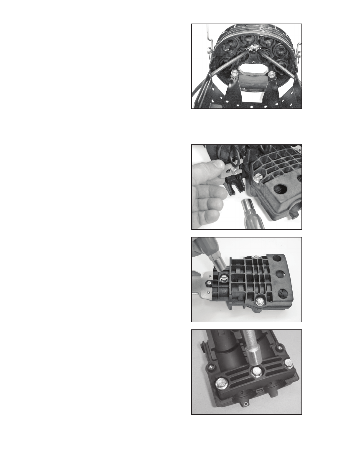
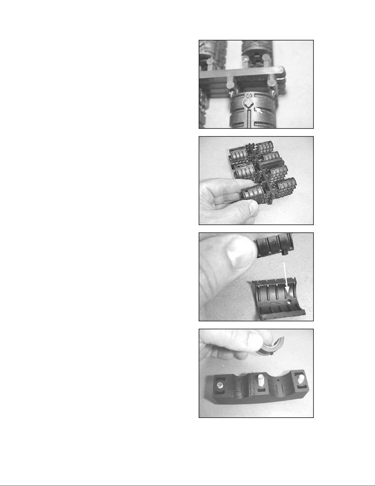
7.5 Assemble the clamp shell(s) onto the bottom
half of the cable housing. Note the orientation
of the pin and socket and assemble accordingly.
Note: Different-sized cables may require different-
sized clamps. Ensure that the correct clamp
set matches the cable when assembling in the
bottom housing and the cable clamp.
8.0 Cable Seal Installation
8.1 First clean the cable sheath thoroughly using an
alcohol wipe. Make sure the cable sheath is free
of any grease or dirt.
Note: Carefully follow health, safety and environmental
instructions as given on the Material Safety Data
Sheet for the alcohol wipe.
Scuff the first 3" of each cable sheath using
supplied sheath scuff. Ensure the cable is
completely scuffed around the perimeter of the
cable.
Hint: Scuffing is easier if you tear the sheath scuff in
narrow strips along the length of the strip.
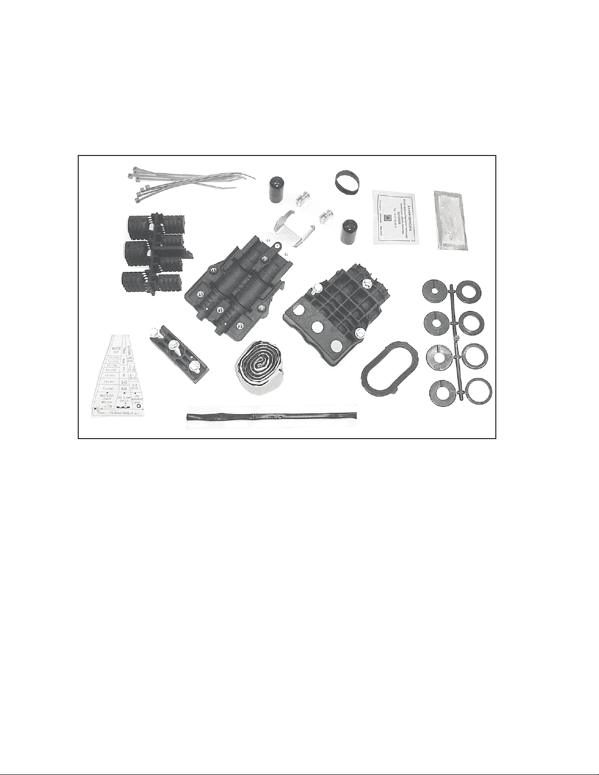
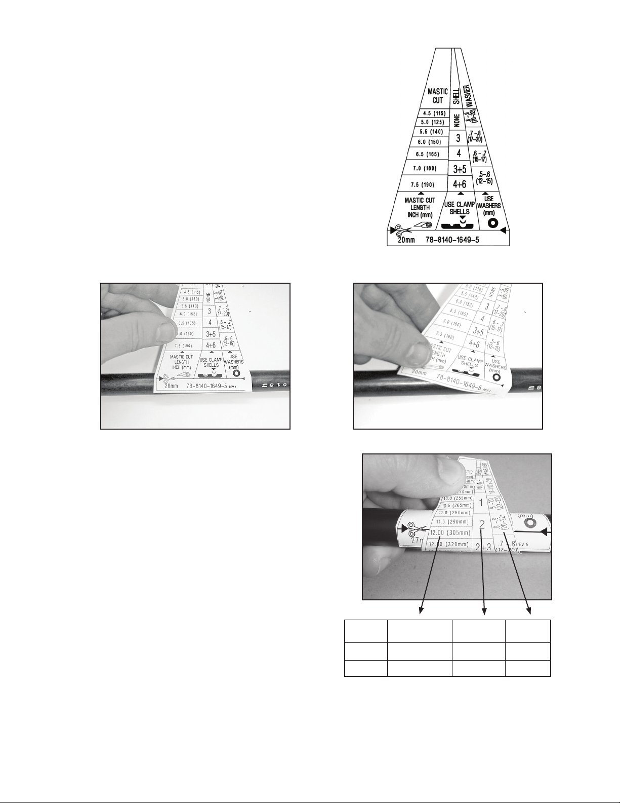
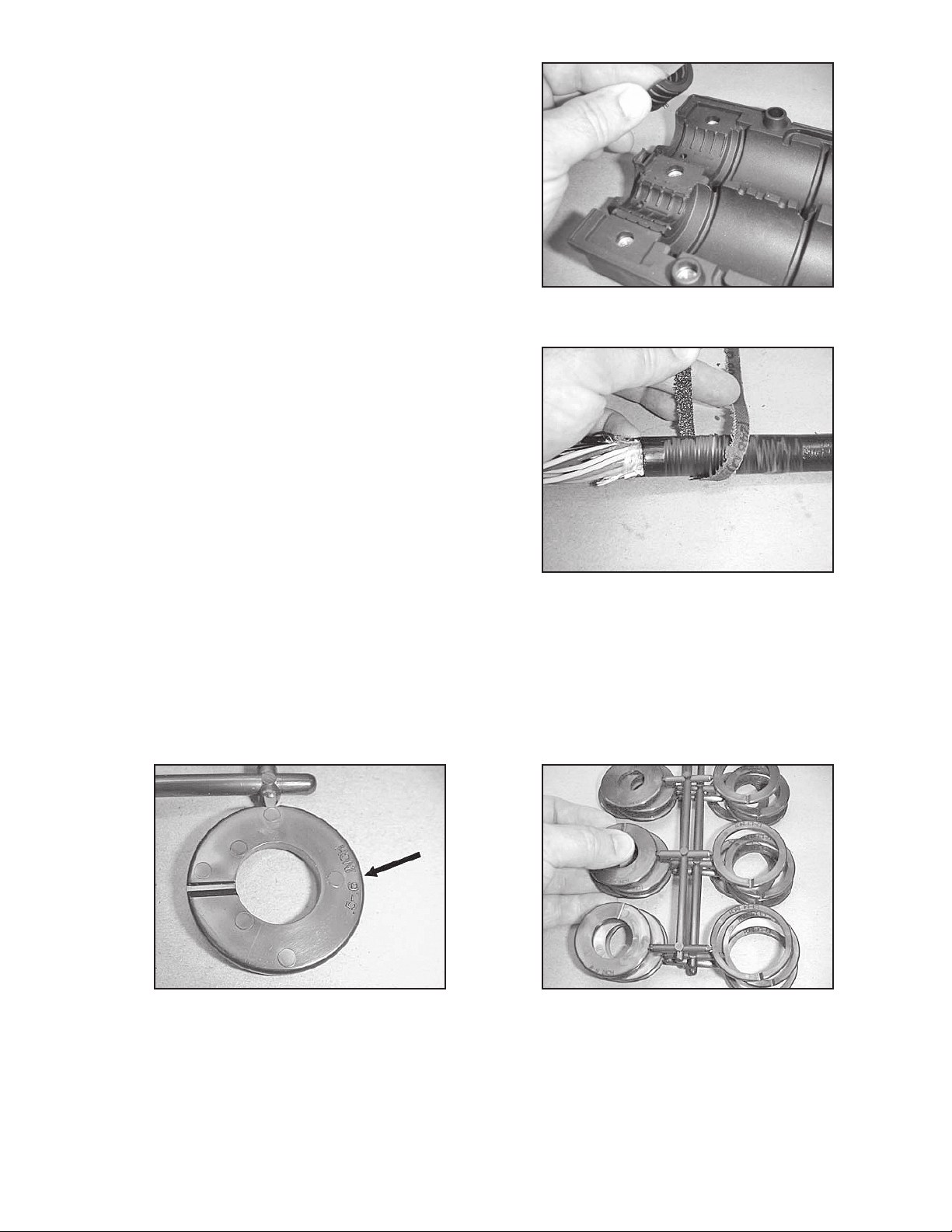
Washer Selection
8.2 Locate and remove two washers on parts trees for each cable (four washers total). Note that washer
sizes are labeled on the washer as shown below. Note that inches are on one side of the washer and
millimeters are on the other side.
Note: See chart in section 6.2 for required washer.

10 78-8140-3820-0-B
Mastic Collar Build
8.3 Mark the cables approximately .25 inches (6
mm) from the end of sheath. This is to locate
the mastic collar.
8.4 Washers can be split along the notch for
installation over the cable.
8.5 Install two washers on each cable near the
sheath end as shown..
8.6 Unroll the mastic and measure out the required
amount. Repeat for second cable.
Note: See chart in section 6.2 for required mastic length.
Note: Warm mastic before use if temperature is below
50˚F (10˚C).

11
78-8140-3820-0-B
8.7 Trim the corners from the mastic, forming points at both ends.
8.8 Wrap the mastic starting .25 inches (6 mm)
from the sheath end. Wrap the mastic evenly
around the cable. DO NOT STRETCH THE
MASTIC.
8.9 The release liner can be wrapped around the mastic collar temporarily to keep the mastic clean. Be
sure to remove the liner before installing the cable into 3M™External Cable Assembly Module (ECAM)
Double Cable Entry Port ECAM-20 mm-D housing. Relocate washers next to the collar. Repeat for
second cable.

12 78-8140-3820-0-B
8.10 Peel the mastic rope from the liner and place into the groove in the 3M™External Cable Assembly Module
(ECAM) Double Cable Entry Port ECAM-20 mm-D bottom half. Press the mastic rope in place and route
as shown. Make sure at least .25 inches (6 mm) of the mastic rope extends out both ends as shown.
8.11 Install the first cable into ECAM housing
bottom half. Note the grooves in the housing for
locating washers.
Note: If different-sized cables are used, ensure the cable
is placed into the correct cable clamp shell set in
the bottom housing.
Note: On cables prepared for grounding, install the cable
into the bottom housing with the cable sheath tab
facing up as shown.
8.12 Install the second cable into the housing. Note
that the washers are offset from the first set.
Note: Ensure the washers are properly seated into their
corresponding grooves in the bottom housing.

13
78-8140-3820-0-B
8.13 Install the cable clamp by positioning it over the
cable set.
Note: If different-sized cables are used, ensure that the
cable is placed into the correct cable clamp shell
set in the bottom housing.
8.14 Start the center clamp screw and lightly tighten.
Evenly tighten the two outer screws along with
the center screw by alternating between. Torque
the three clamp screws to 30 inch-lbs.
8.15 Place top half of the 3M™External Cable Assembly Module (ECAM) Double Cable Entry Port ECAM-20
mm-D over the bottom half. Align the top and bottom housings and squeeze the halves together evenly.
CAUTION
Do not pinch fibers between halves.
8.16 Start all three of the screws. Then evenly tighten
all three screws by alternating between screws.
B
A
A

14 78-8140-3820-0-B
8.17 Finish tightening the two screws marked 'A' until the gaps between the halves under are closed or nearly
closed. Then finish tightening the screw marked 'B'. Torque all three screws to 45 in.-lbs.
Note: Do not exceed 50 in.-lbs. of torque
8.18 Trim excess mastic with snips or a knife.
Note: Do not cut, flush or pull out the mastic rope. Leave
1/8-inch (4mm) of the ends of the rope mastic
protruding.
8.19 Press the mastic flat using a finger tip.
9.0 Cable Strength Member Installation; For all loose buffer tube and
dielectric central tube cables
9.1 Remove the vinyl caps and the cable strength
member (CSM) clamps from the CSM bracket.
Position the CSM rod next to the bracket and
trim it to fit as shown.

15
78-8140-3820-0-B
9.2 Reinstall the CSM clamps as shown and torque
to 25 inch-lbs.
9.3 Cut a 1/2" (13 mm) slit in each cap. Then install
the protective cap over CSM clamp. Position
slit as shown.
9.4 Color-coded cable ties can be installed at this
time to attach caps and can also be used to
identify feeder or distribution cables.
10.0 Cable Strength Member Installation; For armored loose tube cable
10.1 Please refer to 4460-D-SS instruction manual, 78-8135-4338-2 (3M™Scotchlok™Shield Bond
Connectors 4460-D, 4460-DS, 4460-DS-SS) for shield bond installation.

16 78-8140-3820-0-B
11.0 Cable Strength Member Installation; For armored central tube cable
11.1 Please refer to 4460-D/FO-SS instruction manual, 78-8128-0289-6 (3M™Scotchlok™ Shield Bond
Connector Assembly 4460-D/FO and 4460-D/FO-SS) for shield bond installation.
12.0 Ground Wire Installation
12.1 Metallic Version: Please refer to Instruction Manual 78-8128-0289-6-C 3M™Scotchlok Shield Bond
Connector Assembly 4460-D\FO for ground wire installation.
12.2 Non-Metallic Isolated version: Please refer to Instruction Manual 78-8128-0289-6-C 3M™Scotchlok
Shield Bond Connector Assembly 4460-D\FO-SS for ground wire installation.
13.0 3M™External Cable Assembly Module (ECAM) Double Cable Entry
Port ECAM-20 mm-D Installation
13.1 Lightly lubricate the oval gasket using the
supplied silicone lubricant before installing the
gasket into the groove in the base of the 3M™
Fiber Dome Closure.
Note: Follow health, safety and environmental
information. Refer to product label or the Material
Safety Data sheet for silicone lubricant.
13.2 Feed the cable through the oval port
CAUTION
Do not the kink fiber. Handling small groups of
buffer tubes reduces the chances of kinking.

17
78-8140-3820-0-B
13.3 Position the 3M™External Cable Assembly Module (ECAM) Double Cable Entry Port ECAM-20 mm-D
assembly with the CSM bracket facing down.
Correct Incorrect
13.4 Loosen clamps and position over double
cable assembly ECAM assembly as shown.
Torque screw to 45 inch-lbs.
14.0 3M™Double Cable Entry Port ECAM-20 mm-D Accessories
UPC Number 3M I.D. Number Description
0-00-51115-19196-1 80-6113-1702-7 3M™External Cable Assembly Module (ECAM) 18 mm, 20 mm and 27 mm
Cable Ground (6 AWG)
0-00-51115-19198-5 80-6113-1704-3 3M™External Cable Assembly Module (ECAM) Cable Ground (14 AWG)
0-00-54007-92757-0 80-6108-4444-3 3M™Scotchlok™Shield Bond Connector Assembly 4460-D\FO
80-6113-8269-0 3M™Scotchlok™Shield Bond Connector Assembly 4460-D\FO-SS

3M, Scotch and Scotchlok are trademarks of 3M Company.
Important Notice
All statements, technical information, and recommendations related to 3M’s products are based on information believed to be reliable,
but the accuracy or completeness is not guaranteed. Before using this product, you must evaluate it and determine if it is suitable for
your intended application. You assume all risks and liability associated with such use. Any statements related to the product which are
not contained in 3M’s current publications, or any contrary statements contained on your purchase order shall have no force or effect
unless expressly agreed upon, in writing, by an authorized officer of 3M.
Warranty; Limited Remedy; Limited Liability.
This product will be free from defects in material and manufacture for a period of one (1) year from the time of purchase. 3M MAKES
NO OTHER WARRANTIES INCLUDING, BUT NOT LIMITED TO, ANY IMPLIED WARRANTY OF MERCHANTABILITY OR FITNESS FOR
A PARTICULAR PURPOSE.If this product is defective within the warranty period stated above, your exclusive remedy shall be, at
3M’s option, to replace or repair the 3M product or refund the purchase price of the 3M product. Except where prohibited by law,
3M will not be liable for any indirect, special, incidental or consequential loss or damage arising from this 3M product,
regardless of the legal theory asserted.
3
Communication Markets Division
6801 River Place Blvd.
Austin, TX 78726-9000
1-800-426-8688
www.3MTelecommunications.com
Please Recycle. Printed in USA.
© 3M 2011. All Rights Reserved.
78-8140-3820-0-B
Table of contents
Other 3M Cables And Connectors manuals

3M
3M Fibrlok II 2539 User manual

3M
3M Cold Shrink QS-III Splicing Kit User manual

3M
3M 8832-JG1 UPC SM User manual

3M
3M ReLoad SRL User manual

3M
3M 5321 User manual

3M
3M 4604GW User manual

3M
3M 4655 User manual

3M
3M 3443-112 Assembly instructions

3M
3M 103 12R1-00 Series User manual

3M
3M 3443-107N Assembly instructions
Popular Cables And Connectors manuals by other brands

Amphenol Socapex
Amphenol Socapex RJField 544 Series manual

Insignia
Insignia NS-GPS4CCK101 Quick setup guide

ERNI
ERNI MaxiBridge CSI Processing Specification

PCB Piezotronics
PCB Piezotronics 010P20 Installation and operating manual

NCR
NCR 7403-K112 Kit instructions

SCHURTER
SCHURTER 4783 Series Operation manual