3M 8800 APC/AS User manual

October 2010
78-8140-1581-0-C
3M™ No Polish Connector 8800-APC/AS
SM SC/APC, Angle Splice, 250/900-µm
Instructions

2
Contents
1.0 Summary.............................................................................................................................................3
2.0 ConnectorPreparation........................................................................................................................4
3.0 FiberPreparation.................................................................................................................................4
4.0 FiberInsertion.....................................................................................................................................7
5.0 SpliceActuation..................................................................................................................................8
Safety Precautions
Protective Eyewear
c CAUTION
Safetyglassesshouldbewornwhenhandlingchemicalsandcleavingtheopticalber
Chemical Precautions
c WARNING
Storage,useanddisposalofisopropylalcoholshouldbeperyourcompanyhealth,safetyandenvironmentalinstructions.Referto
materialsafetydatasheetforhealthhazards,safehandling,properuseandcontrolmeasures.
c CAUTION
Productcontainsphenylmethylsilicone(63148-58-3),hydrophobicsilica(68611-44-9)andmaycauseminimaleyeirritation.Avoid
contactwitheyesandwashhandsbeforeeatingorsmoking.Uponeyecontact,immediatelyusheyeswithwaterwhileholding
eyelidsopenandcontinueushingfortenminutes.Contactaphysician.Uponskincontact,washwithsoapandwater.Product
Information:MaterialSafetyDataSheetor3MCompany,St.PaulMN,55144-1000,(651)733-1110Operator55
Bare Fiber Handling
c CAUTION
Cleavedglassbersaresharpandcanpiercetheskin.Usetweezerswhenhandlingshardsanddisposeofthemproperlyperyour
companyhealthandsafetyinstructions.
Fiber/Cable Handling
c CAUTION
Opticalbercanbedamagedbyexcessivetensile,compressiveandbendingforces.Consultthemanufactures'specicationsfor
properhandlinginstructions.
Laser Safety
c CAUTION
Taketheproperprecautionswhenworkingwithopticalberbecauseinvisiblelaserlightmaybepresent.Theprincipallaserhazard
whenworkingwithberopticsisinjurytotheeye.Neverlookdirectlyintotheberorconnectorusingthenakedeyeoramicroscope.

3
1.0 Summary
1.1 3M™NoPolishConnector8800-APC/ASterminates250µmor900µmsingleberswithSC/APCinterfaceand
anglespliceforsuperioropticalreturnlossperformance.
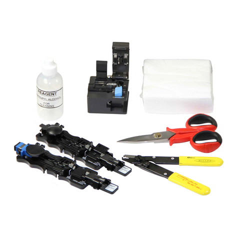
1.2 Requiredtools,whichareavailableinthe3M™FiberOpticAngleCleaveKit2565.
3M™ Fiber Optic
Angle Cleaver 2535
3M™ No Polish Connector
Assembly Tool
8865-AT
3M™ Fiber Holder
3M™ Fiber Stripper 6365-KS
Isopropyl
Alcohol Fiber Shard
Container
Lint-Free
Cloths
1.3 Forsituationswhereasuitableworkareaisnotavailable,thecaseandplasticplate,whichareincludedinthe
2565kit,cancreateaworksurface.Thecasecanbesetonlevelground,onavehicle,orhungbythehookand
shoulderstrap.
1.4 Addonefullbottle(1.8.oz./53ml.)of99%pureisopropylalcoholintolint-freeclothcontainerto
pre-moistenwipes.

4
2.0 Connector Preparation
2.1 Priortoeachtermination,cleanalltools,including
berholder,withalint-freeclothandreagent-grade
isopropylalcohol.
2.2 Carefullyremoveconnectorbodyfromthebag.
Removethedustcapsfromthefrontandrearofthe
connectorbody.
2.3 Opentheactuatorbuttonontheassemblytoolbase.
Insertconnectorintocouplinginthetoolwithwhite
actuationcapfacingupwards,pushingforwarduntil
itclicks.
3.0 Fiber Preparation
3.1 Openallthreeanglecleaverclampsandlevers.
3.2 Carefullycleanthecleaverclampsusingasmall
brush.
3.3 For900µmbufferber,cutthebuffer.Ifthe900µm
slideseasilyfromtheberitisloosetubeorsemi-
tightbufferedber.

5
Inthisinstance,usetheberholders'clampto
prohibitthebufferfrommovingorstretchingduring
thestrippingprocess.Placetheberintotheber
holdergroove,labeled"semi-tight",withtheberto
bestrippedprotrudingfromthebackoftheholder.
Closetheclampandproceedtostripandclean
theber.Oncecomplete,removetheberfrom
theholder.Ifthe250µmfiberstillmovesinsidethe
900µmbufferafteritisclampedinthe"semi-tight"
groove,thentheconnectormustbeinstalledonthe
250µmfiber.Stripatleasteightinches(203mm)of
the900µmbufferandcompletetheinstallation.
Semi-Tight Buffered Fibers
3.4 Forallbers,stripthe900µmand250µmcoatings
exposingglassfor1.67"to1.77"(42.5mmto
45mm).
3.5 Toverifythecorrectstriplength,usethewhite
marksontheleftsideofthecleaver.Alignthe
coatingedgetotheleftedgeofthecleaverandthe
bertipshouldbebetweenthetwowhitelines.
3.6 Cleanberwithalcoholandlint-freecloth.
3.7 Withthetwocoversandclampopen,placethe
assemblytoolberholderontothecleaver.Pushthe
holdertowardthecleaverbladeuntilitstops.
3.8 Placeberinanglecleaversothatthecoatingedgeis
at8.0±0.5mm.
Note: Makesurethatthenaturalbowintheberis
facingdownandlayingproperlyinthebottomof
V-grooveinbothcleaverclamps1&2.
Coating edge at 8.0 mm

6
3.9 Closethecleaverclamp#1rst.Thisprocesssetsthe
appropriatecleavelength.
3.10 Closethecleaverclamp#2.
Note: Ensurethereisnoberbowbetweenthetwoclamps.Ifthere
isabow,openbothclampsandrepeatsteps3.9and3.10.
3.11 For250µmberandtightbuffer900µmber,theber
shouldbeplacedintheberholdertoolgroovewhich
islabeled“Tightbuffer”.Forsemi-tightbufferber,
itshouldbeplacedinthegroovelabeled“Semi-tight
buffer”.Thisprovidestheproperclampingforceonthe
900µmbuffer.
Tight buffer
Semi-tight buffer
3.12 Closethetwocoversandtheclampontheberholder.
Thefunnelcoverwillnotclosecompletelywhileinthe
cleaver.Donotforceorcovercanbreak.
funnel cover
3.13 Depresscleaveactivationlever(#3)andholditdownuntil
Clamp#2slideassemblyhasfullymovedtotheright,
indicatingthattheanglecleaveiscomplete.
Note: Ifberdoesnotbreakimmediatelyuponactivation,
oritbreakssothatthecleavelengthisnot8mm,
thenopenclampsandcarefullycleanthecleaver
clampswithabrushandalcohol-soakedlint-free
cloth.Cutexposedberandstrip,cleanandcleave
again.Ifissuespersist,rotatecleaverbladetothe
nextpositionusingthesuppliedwrenchesand
tryagain.
3.14 Opencleaverclamp#1andremoveberholderandber
fromcleaver.
Note: Donotopenactivationleveraftercleavinguntilber
holderandberhavebeenremoved.

7
3.15 Verif ythe8mmcleavelengthagainbyusingthelength
gaugeontheassemblybase.The8mmcleavelengthis
measuredfromtheendofthe900µmbuffertotheendof
thecleavedber.Onsemi-tightbufferber,the250µm
coatingmayprotrude1mmpastthe900µmsemi-tight
buffer.Re-strip,cleanandcleavetheberifnecessaryto
meetlengthrequirements.
3.16 Openactivationlever#3andclamp#2ofanglecleaver.
Disposeofbershardpercompanypractice.
4.0 Fiber Insertion
4.1 Slidetheberholder’sguidefunnelfullyforwardandclose
thefunnelcover.Anaudibleclickcanbeheard.Checkfor
propercleavelengthagainbyinspectingtheamountofber
protrudingbeyondthefunnelendoftheholder.Theamount
ofexposedbershouldbefrom0to1mm(0.04").
4.2 Placeberholderintheassemblytoolbase.
4.3 VERYSL OW LYslidetheberholdertowardsthe
connector.Abowintheberisstartedoncethewhitelineon
theberholderisevenwiththewhiteline(BOWSTART)on
thebase.Ifabowisnotseen,strip,cleanandcleavetheber
asshowninsection3andtryinstallationagain.
Bow Start
Slide very slowly
Note: Seephotoin4.4formoredetail.
4.4 Ifabowisseenbeforethewhitelineontheholdermeets
thewhitelineonthebase,thenstrip,clean,andcleavethe
berasshowninSection3andtryagain.
When white lines
meet, Fiber Bow
should start.

8
4.5 Whentheberholderispushedtowardtheconnectorand
stops,theberbowshouldbeseenasbelow.Theberwill
bowandliftthemiddlecoverforrigidbersandremain
closedforexiblebers.
fiber bow
middle cover
5.0 Splice Actuation
5.1 Whilethereisaberbow,pressactuatorbuttonrmly
toactuatethesplice.Anaudibleclickwillbeheardwhen
properlycompleted.
Note: Ifcontinuityvericationisrequiredoryouneed
totestthelinkpriortoplacinginserviceyouwill
performthisstepnow.Donotproceedtostep
5.2untiltestingiscomplete.Ifre-terminationis
required,pleaseskiptoSection6,3M™NoPolish
Connector(NPC)Re-termination.
5.2 Pressreleaselevertoallowforwardmotionoffunnel.
Pushearstomovefunnelforwardandactuatebuffer
clamp.
5.3 Opentheclampandliftthecoverstoreleaseber.
5.4 Slideberholderfromactuationtool.
Optional:3M™NoPolishConnectorcanbetestedinthetool
usingaSCcoupling.
5.5 Pullconnectorfromcouplingandcleanconnectorend
facewithisopropylalcoholandalint-freecloth.
5.6 Afterremovingconnectorfromthecoupling,replace
thedustcapontheferruleuntilconnectorisreadytobe
placedinservice.

9
6.0 3M™ No Polish Connector (NPC)
Re-termination
6.1 Tore-terminatetheNPCconnector,removetheconnector
fromthecouplingontheactuationtoolandberholder
priortoactivatingthebufferclampattheboot.Takethe
cappopperprovidedforyouintheboxofNPCconnectors
andplaceitinthethreeslotsprovidedontheundersideof
theNPCconnectorshellasshown.
6.2 FirmlypressthecappopperintotheNPCconnectorshell
untiltheactivationcapisdepressed.
Removeberandinsertconnectorwiththeactuation
capfacingupinthecoupling,pushingforwarduntil
itclicks.Followsteps3.0through5.1tore-terminate
theNPCconnector.
6.3 Uponvericationthatconnectorhasbeenterminated
satisfactorily,slidetheberholderupintothebackof
theboot.Returntosteps5.2through5.6tocompletethe
terminationoftheNPCconnector.
Forinformationregardingthepropereldtesting
procedurerefertotheTechTiponthe3MCMDwebsite,
www.3m.com/telecom

3M and Fibrlok are trademarks of 3M Company.
Important Notice
All statements, technical information, and recommendations related to 3M’s products are based on information believed to be reliable, but the accuracy or
completeness is not guaranteed. Before using this product, you must evaluate it and determine if it is suitable for your intended application. You assume
all risks and liability associated with such use. Any statements related to the product which are not contained in 3M’s current publications, or any contrary
statements contained on your purchase order shall have no force or effect unless expressly agreed upon, in writing, by an authorized officer of 3M.
Warranty; Limited Remedy; Limited Liability.
This product will be free from defects in material and manufacture for a period of one (1) year from the time of purchase. 3M MAKES NO OTHER
WARRANTIES INCLUDING, BUT NOT LIMITED TO, ANY IMPLIED WARRANTY OF MERCHANTABILITY OR FITNESS FOR A PARTICULAR PURPOSE.
If this product is defective within the warranty period stated above, your exclusive remedy shall be, at 3M’s option, to replace or repair the 3M product or
refund the purchase price of the 3M product. Except where prohibited by law, 3M will not be liable for any indirect, special, incidental or con-
sequential loss or damage arising from this 3M product, regardless of the legal theory asserted.
3
Communication Markets Division
6801 River Place Blvd.
Austin, TX 78726-9000
1-800-426-8688
www.3MTelecommunications.com
Please Recycle. Printed in USA.
© 3M 2010. All Rights Reserved.
78-8140-1581-0-C
3M™ No Polish Connector, Kit and Tool Descriptions Packaging
8800-APC/AS*
No Polish Connector SM SC/APC Angle
Splice, 250/900 µm
(green housing, green boot)
60/package
2565 Fiber Optic Angle Cleave Kit 1/package
2535 Fiber Optic Angle Cleaver 1/package
8865-AT No Polish Connector Assembly Tool 1/package
*Every box of 60 contains a 3M No Polish Connector Tool 8865-AT.
3M™ Fiber Optic Angle Cleave Kit 2565 Contents
2535 Fiber Optic Angle Cleaver with brush, tweezers, maintenance parts and spare rubber pads
2501-AS Fibrlok™ Angle Splice Assembly Tool
8865-AT No Polish Connector Assembly Tool
6362-TH Fiber Stripping Tool
6365-KS Kevlar Snips
Lint-Free Cloths, Cleaning Alcohol Bottle, Work Plate, Fiber Shard Container
8800-APC/AS No Polish Connector SM SC/APC Angle Splice, 250/900 µm (2 ea.)
2529-AS Fibrlok™ II Angle Fiber Splice (6 ea.)
2540-AS Fibrlok™ 250 µm Angle Fiber Splice (5 ea.)
Table of contents
Other 3M Cables And Connectors manuals

3M
3M TTS-5-1-OJ User guide

3M
3M 90-B1 User manual

3M
3M 5415A-IJ User manual

3M
3M 8800-APC/AS/AGC User manual

3M
3M 7700 Series Operating instructions

3M
3M 7620-S-2 User manual

3M
3M Cold Shrink QS-III Splicing Kit User manual

3M
3M ReLoad SRL User manual

3M
3M Litmann Quality 3100 User manual

3M
3M 5810-BI-15 User manual