3M Bair Hugger 775 User manual

Model 775
Warming Unit
Operator’s Manual
Normothermia System
-Unidade de Aquecimento
3M™ Bair Hugger™, Modelo 775
Manual do Usuário
=3M™ Bair Hugger™
HModel 775 aparatu do
terapii grzewczej 3M™ Bair Hugger™
Instrukcja obsługi
J775-ös típusszámú
3M™ Bair Hugger™ melegítőegység
Felhasználói kézikönyv
FOhřívací jednotka
3M™ Bair Hugger™, model 775
Návod k obsluze
Q„3M™ Bair Hugger™“
775 modelio šildomasis įtaisas
Naudotojo vadovas
M
d3M™ Bair Hugger™
Isıtma Ünitesi Model 775
Kullanım Kılavuzu
I3M™ Bair Hugger™ 775 型加温器
操作手册
U
13M™ Bair Hugger™
Warming Unit Model 775
Operator’s Manual
2areil de réchauffement
Bair Hugger™ 3M™, modèle 775
Manuel de l’utilisateur
33M™ Bair Hugger™-Wärmeeinheit,
Modell 775
Bedienungsanleitung
4Unità riscaldante
3M™ Bair Hugger™ modello 775
Manuale d’uso
5Unidad de calentamiento
modelo 775 Bair Hugger™ de 3M™
Manual del operador
63M™ Bair Hugger™-verwarmingsunit
model 775
Bedieningshandleiding
73M™ Bair Hugger™ värmeenhet,
modell 77521
Användarhandbok
83M™ Bair Hugger™ varmeenhed,
model 775
Betjeningsvejledning
93M™ Bair Hugger™ Varmeenhet,
modell 775
Brukerhåndbok
03M™ Bair Hugger™
-lämpöpuhallinmalli 775
Käyttöopas
3M™ Bair Hugger™ 775


1English........................................... 1
2Français ......................................13
3Deutsch ..................................... 27
4Italiano .......................................39
5Español ....................................... 51
6Nederlands................................63
7Svenska...................................... 75
8Dansk ......................................... 87
9Norsk..........................................99
0Suomi ..........................................111
-Português .................................123
=..................................135
HPolski.........................................147
JMagyar......................................159
FČesky.........................................171
QLietuvių Kalba ......................... 183
M....................................195
dTürkçe..................................... 209
I日本語........................................221
U..................................231
Model 775
Warming Unit
Operator’s Manual
Normothermia System
Description:
Base File Name:
Software:
SGS Contact:
Email:
Printer:
Printer Location:
Supplier:
3M
TM
Bair Hugger™
Patient Adjustable Warming Unit
Requester: Frank Boeshart/Debra Staack
Reference:
Die # / Doc. Size: 8.5" x 11"
Item Spec#:34-8718-8811-0
Supersedes#:
Cat/Product#:Model 775
Structure#:
Manual
PA: 34871888110.indb
GA:
InDesign CC 2014 - BOOK
PROCESS
BLACK
PMS
280
4394547 5
08.02.16 New Build kmh
08.04.16 Updated Final pages number. Jer
08.25.16 Alts per PDF file kmh
08.30.16 Final release. DJ
09.24.16 Adjust Center Margins to 1 in. to accomodate spiral binding and Final Release kmh


1
GB / 34-8718-8811-0
1Table of Contents
Introduction................................................................................................................................................................................... 3
Description Of The 3M™ Bair Hugger™ Temperature Management System ......................................................... 3
Indications.............................................................................................................................................................................. 3
Denition Of Symbols ......................................................................................................................................................... 3
Contraindications, Warnings, Cautions And Notices ........................................................................................................... 3
Explanation Of Signal Word Consequences................................................................................................................... 3
CONTRAINDICATION: ...................................................................................................................................................... 4
WARNING: ............................................................................................................................................................................ 4
CAUTION: ............................................................................................................................................................................. 4
Notices ................................................................................................................................................................................... 5
Proper Use And Maintenance............................................................................................................................................ 5
Read Before Servicing Equipment .................................................................................................................................... 5
Overview And Operation............................................................................................................................................................ 5
Warming Unit Power-On-Reset......................................................................................................................................... 6
Overview Of Control Panel................................................................................................................................................ 6
Mounting The Warming Unit To An IV Pole .....................................................................................................................7
Instructions For Use......................................................................................................................................................................7
Viewing The Temperature Mode Timer............................................................................................................................7
What To Do In Case Of An Over-Temperature Condition ............................................................................................7
What To Do If A Fault Condition Occurs..........................................................................................................................7
General Maintenance And Storage .......................................................................................................................................... 8
Cleaning Instructions........................................................................................................................................................... 8
Storage ................................................................................................................................................................................... 8
Technical Service And Order Placement ................................................................................................................................ 8
When You Call For Technical Support ............................................................................................................................. 8
In-Warranty Repair And Exchange ................................................................................................................................... 8
Specications........................................................................................................................................................................ 8


3
GB / 34-8718-8811-0
13M™ BairHugger™ Warming Unit Model775
Operator’sManual
Introduction
Description of the 3M™ BairHugger™ Temperature
ManagementSystem
The BairHugger temperature management system consists of a
Model 775warming unit (with optional rolling stand, and other
accessories) along with a 3Mwarming blanket, BairHugger warming
gown, or the 3M™ Ranger™ 241blood/fluid warmingset.
The BairHugger warming unit is attached to the warming blanket or
warming gown by means of a flexible hose. Warm air is generated
in the warming unit and flows through the warming unit hose and
into the blanket or gown. Depending on the model, the 3Mblanket
or gown is placed either around, over, or underneath the patient.
Small perforations on the blanket or gown allow the warm air to be
dispersed over the patient. For blood/fluid warming applications, the
Model 241blood/fluid warming set is inserted in the warming unit
hose. When the warming unit is turned ON and a temperature setting
is selected, warm air flows over the Model 241tubing and warmed
blood/fluid exits from the distal end of the tubing. For additional
information on 3Mblankets, gowns, the 241warming set, or other
accessories visit us online atbairhugger.com.
This manual includes operating instructions and warming unit
specifications for the Model 775warming unit. You can use the
Model 775warming unit in all clinical settings where the patient may
feel too warm or too cold; including the operating room to provide
patient temperature management. For information about using
3Mblankets, gowns or the 241blood/fluid warming set with the
Model 775warming unit, refer to the respective Instructions forUse.
Indications
The BairHugger temperature management system is intended
to prevent and treat hypothermia. In addition, the temperature
management system can be used to provide patient thermal comfort
when conditions exist that may cause patients to feel too warm or too
cold. The temperature management system can be used with adult
and pediatricpatients.
• The BairHugger temperature management system should
only be used by trained medicalprofessionals.
• Federal law (USA) restricts this device to sale by or on the
order of a licensed healthcareprofessional.
Definition ofSymbols
The following symbols may appear on the product’s labeling or
exteriorpackaging.
An equipotentiality plug (grounded) conductor
other than a protective earth conductor or a
neutral conductor, providing a direct connection
between electrical equipment and the potential
equalization busbar of the electrical installation.
Please consult IEC 60601-1 forrequirements.
Fuse
Type BF equipment (patientapplied)
Date ofmanufacture
Manufacturer
Voltage, alternating current(AC)
This system is subject to European WEEE
Directive2002/96/EC. This product contains
electrical and electronic components and
must not be disposed of using standard refuse
collection. Please consult local directives for
disposal of electrical and electronicequipment.
Protective earthground
No freehosing
High fansetting
Low fansetting
Non-explosionproof
Consult instructions foruse
Follow instructions foruse
Recycle to avoid environmental contamination.
This product contains recyclable parts. For
information on recycling, please contact your
nearest 3MService Center foradvice.
Attention; see instructions foruse
Keepdry
Temperaturelimit
Contraindications, Warnings, Cautions andNotices
Explanation of Signal WordConsequences
!
WARNING: Indicates a hazardous situation which, if not
avoided, could result in death or seriousinjury.
!
CAUTION: Indicates a hazardous situation which, if not
avoided, could result in minor or moderateinjury.
NOTICE: Indicates a situation which, if not avoided, could result in
property damageonly.

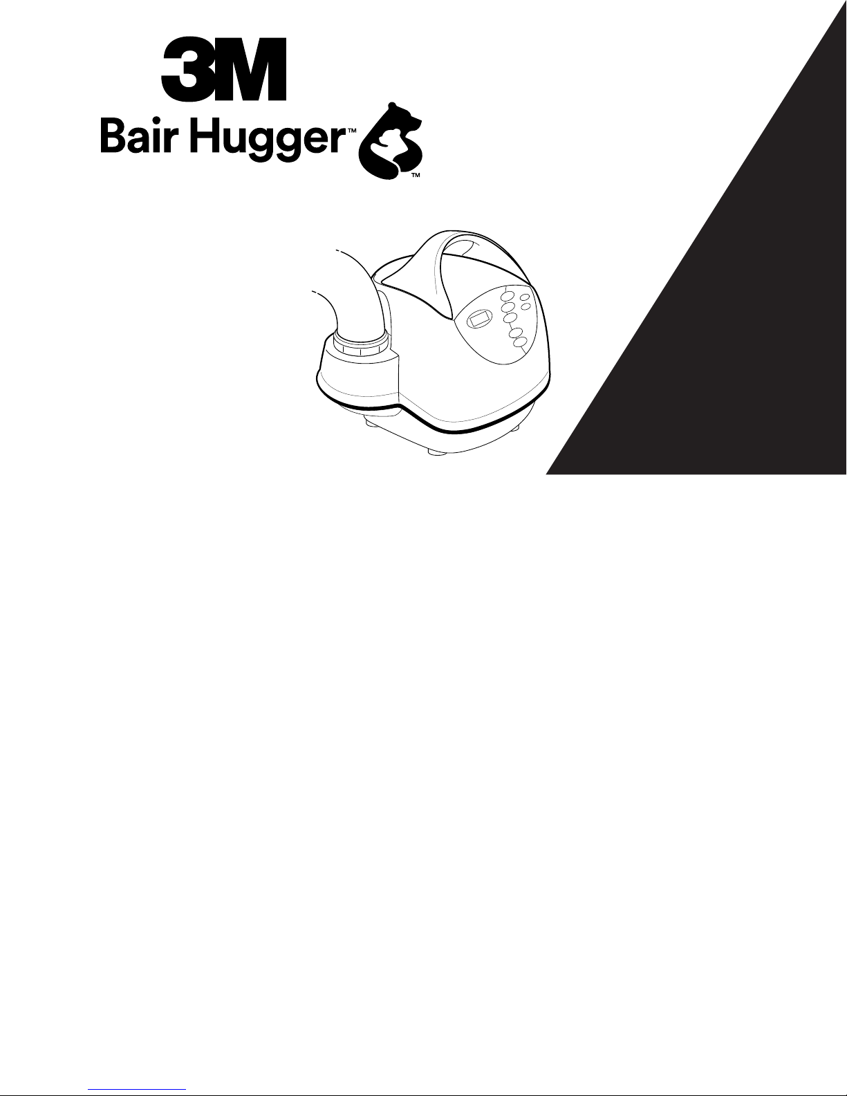
43M™Bair Hugger™ Model 775 Warming Unit – Operator’s Manual
!
CONTRAINDICATION: To reduce the risk of thermalinjury:
• Do not apply heat to lower extremities during aortic
cross-clamping. Thermal injury may occur if heat is applied
to ischemiclimbs.
!
WARNING: To reduce the risk of thermalinjury:
• The BairHugger Model 775warming unit has been
designed to operate safely ONLY with 3Mdisposable
warming products. Use with other products may cause
thermal injury. To the full extent permitted by law, the
manufacturer and/or importer declines all responsibility for
thermal injury resulting from the warming unit being used in
conjunction with non-3Mproducts.
• Do not treat patients with the warming unit hose
alone. Always attach the hose to a 3Mwarming
blanket/gown before providing warmingtherapy.
• Do not allow the patient to lie on the warming unithose.
• Do not allow the warming hose to directly contact the
patient’s skin during warmingtherapy.
• Do not leave neonates, infants, children and other
vulnerable patient populations unattended during
warmingtherapy.
• Do not leave patients with poor perfusion unmonitored
during prolonged warmingtherapy.
• Do not place the non-perforated side of the warming
blanket/gown on the patient. Always place the perforated
side (with the small holes) directly on top of the patient in
contact with the patient’sskin.
• Do not connect a torn or damaged warming blanket/gown
to the warmingunit.
• For over-body warming blankets and gowns; do not place
patient securement device (i.e. safety strap or tape) over
the warmingblanket/gown.
• For underbody or side channel warming blankets; if a
securement device (i.e. safety strap, tape) is used, ensure
the warming channels are notoccluded.
• Do not place the warming blanket/gown directly over a
dispersive electrodepad.
• Do not continue warming therapy if the red Over-temp
indicator light illuminates and the alarm sounds. Unplug the
warming unit and contact a qualified servicetechnician.
• Do not continue 241blood/fluid warming therapy if the
red Over-temp indicator light illuminates and the alarm
sounds. Immediately stop fluid flow, and discard the blood/
fluid warming set. Unplug the warming unit, and contact a
qualified servicetechnician.
• For the BairHugger flex warming gown; ensure that the
blood pressure cuff, ECG, IV or other lines or cords are
not between the upper sleeve insert and the gown prior to
deploying the upper sleeve warming insert(s), as this could
result in tearing of the insert duringdeployment.
• Do not perform the over-temperature detection system test
while the warming unit is being used for warmingtherapy.
!
WARNING: To reduce the risk of patient injury or death due to
altered drugdelivery:
• Do not use a warming blanket/gown over transdermal
medicationpatches.
!
WARNING: To reduce the risk of injury due to interference
withventilation:
Do not allow the warming blanket/gown or head drape to
cover the patient’s head or airway when the patient is not
mechanicallyventilated.
!
WARNING: To reduce the risk of injury due to patientfalls:
• Do not use a warming blanket/gown to transfer or move
thepatient.
!
WARNING: To reduce the risks associated with hazardous
voltage andfire:
• Keep power cord visible and accessible at all times. The
plug on the power cord serves as the disconnectdevice.
• Only connect to outlets marked “Hospital only,” “Hospital
Grade,” or a reliable groundedoutlet.
• Use only the power cord specified for this product and
certified for the country ofuse.
• Do not allow the power cord to getwet.
• Do not use the warming unit when it appears the warming
unit, power cord or any component is damaged. Replace
the warming unit. Contact 3MTechnicalSupport.
• Do not disassemble the warming unit unless you are a
qualified service technician. There are electrically live
parts within the warming unit when it is connected to a
powersource.
• Connect each warming unit being tested to a separate
powersource.
!
CAUTION: To reduce the risk ofcross-contamination:
• Except for specific BairHugger warming blanket models,
3Mwarming blankets/gowns are not sterile. Each warming
blanket/gown is intended for single patient use ONLY.
Placing a sheet between the warming blanket/gown and
the patient does not prevent contamination of theproduct.
• Clean the warming unit and the outside of the warming unit
hose after each patient use. See “Cleaning Instructions” on
page8.
• Follow applicable regulations when disposing of this
warming unit or any of its electricalcomponents.
• Do not attempt to clean the air filter as it may be
contaminated from use. Discard the filter in a manner
consistent with institutionalprotocol.
• Do not operate the BairHugger warming unit with the
hose detached from the 3Mwarming blanket/gown. The
BairHugger warming unit is intended to be used with
the hose properly attached to its corresponding warming
blanket/gown and in accordance with good practices for
operating room steriletechnique.
!
CAUTION: To reduce the risk of patient or caregiverinjury:
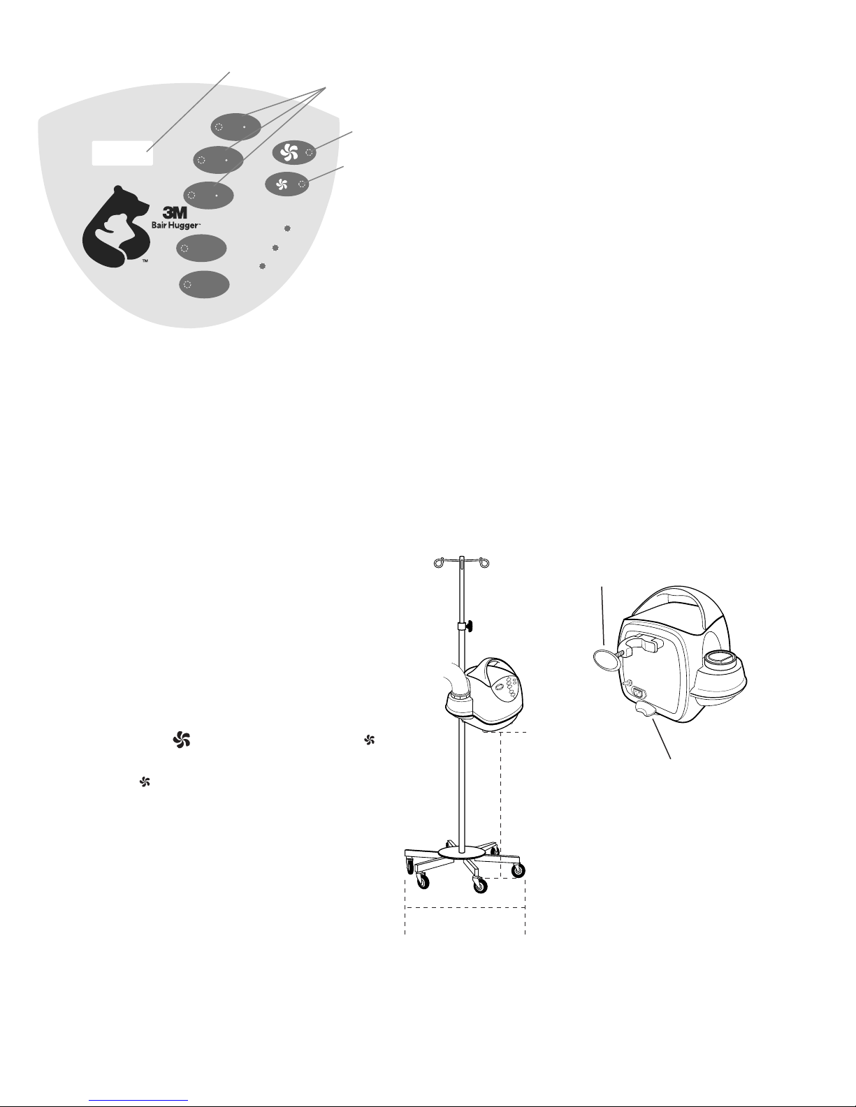
• If mounted on an IV pole, the distance from the bottom of
the warming unit to the floor must be less than 44” (112cm)
and the IV pole wheelbase diameter must be at least 28”
(71cm) to preventtipping.
!
CAUTION: To reduce the risk offire:
• 3Mwarming blankets and gowns are classified as Class I
Normal Flammability as defined by the Consumer Product
Safety Commissions flammable fabric regulation, 16CFR
1610. Follow standard safety protocols when using high
intensity heatsources.
!
CAUTION: To reduce the risk of thermal injury, hyperthermia
orhypothermia:
• 3Mrecommends continuously monitoring core
temperature. In the absence of continuous monitoring,
monitor the temperature of patients who are incapable
of reacting, communicating and/or who cannot sense
temperature a minimum of every 15minutes or according to
institutionalprotocol.

5
GB / 34-8718-8811-0
• Monitor cutaneous responses of patients who are incapable
of reacting, communicating and/or who cannot sense
temperature a minimum of every 15minutes or according to
institutionalprotocol.
• Adjust air temperature or discontinue therapy when the
therapeutic goal is reached, if elevated temperatures are
recorded or if there is an adverse cutaneous response in the
warmedarea.
• Do not place the warming unit on a soft uneven surface,
such as a bed, or a visibly wet surface as the air intake may
become blocked and cause the warming unit to overheat,
compromising the warming unit’sperformance.
• Perform all temperature testing of the warming unit with a
3MModel 22110temperature testunit.
!
CAUTION: To reduce the risk associated with
electromagnetic interference (EMI) due to portable and
mobile radio frequency (RF) communicationsequipment:
• The 3MBairHugger temperature management system has
been tested to be resistant to both EMI and electrostatic
discharge(ESD).
• Install and put into service the 3MBairHugger temperature
management system according to the electromagnetic
compatibility (EMC) information provided in the Guidance
and Manufacturer’sDeclaration.
• Should interference occur, move away from the portable or
mobile RF communicationsequipment.
Notices
1. The BairHugger warming unit meets medical electronic
interference requirements. If radio frequency interference with
other equipment should occur, connect the warming unit to a
different powersource.
2. To avoid warming unitdamage:
• Use proper Electrostatic Discharge (ESD) procedures when
performingmaintenance.
• Do not modify this equipment without authorization from
themanufacturer.
• Do not immerse the warming unit, warming unit parts
or accessories in any liquid or subject them to any
sterilizationprocess.
• Do not use cleaning solutions with greater than 80%
alcohol or solvents, including acetone and thinner, to clean
the warming unit or hose. Solvents may damage the labels
and other plastic parts.
Proper Use andMaintenance
3Massumes no responsibility for the reliability, performance, or
safety of the warming unit if the following eventsoccur:
• Modifications or repairs are performed by
unqualifiedpersonnel.
• The warming unit is used in a manner other than that
described in the Operator’s or ServiceManual.
• The warming unit is installed in an environment
that does not meet the appropriate electrical and
groundingrequirements.
• The warming unit not maintained in accordance with the
procedures described in the ServiceManual.
Read Before ServicingEquipment
All repair, calibration and servicing of the warming unit require the
skill of a qualified, medical equipment service technician who is
familiar with good practice for medical device repair. If service does
not require the manufacturer’s attention, the Model 775Service
Manual provides the technical information needed to service the
warming unit. Perform all repairs and maintenance in accordance
with the instructions in the Service Manual. For additional service
information please contact 3Mtechnicalsupport.
Overview andOperation
Figure B. Model 775Warming Unit – rearview
IV pole clamp
Hose
Hose connection
Power cord
connection
Figure A. Model 775Warming Unit – frontview
Alphanumeric
display
Control Panel
Carrying
handle
Warming UnitPower-On-Reset
The Model 775warming unit automatically performs the following
power-on-reset sequence after you connect the warming unit to a
properly grounded powersource:
• Performs all self-testfunctions.
• Illuminates indicator lights and all pixels in the
alphanumeric displaymomentarily.
• Displays the text “MD 700’s” and the software revision
level in the alphanumericdisplay.
• Sounds the alarm (three low-levelclicks).
• Enters the Standby mode with the high fan setting selected
bydefault.
Note: The low fan setting indicator light will not illuminate
during powerup.
If the warming unit loses power for less than 1second, the warming
unit software will return the warming unit to the operating mode
you selected prior to the power loss. However, if the warming unit
loses power for longer than 1second, the warming unit software will
reset when you restore power. The warming unit will then enter the
Standby mode with the high fan setting selected bydefault.

63M™Bair Hugger™ Model 775 Warming Unit – Operator’s Manual
Overview of ControlPanel
TEMP IN RANGE
FAULT
OVER TEMP
STANDBY
AMBIENT
MODEL 775 43 C
MEDIUM
HIGH
TEMPERATURE
AIR FLOW
38 C
LOW
32 C
System
High Fan
Setting
Alphanumeric Display Temperature
Modes
Low Fan
Setting
Figure C. Model 775 Warming Unit Control Panel
ALPHANUMERICDISPLAY
The alphanumeric display shows the temperature at the end of the
BairHugger warming unit hose in degreesCelsius.
TEMPERATUREMODES
• Press the 32˚C (Low), 38˚C (Med), or 43˚C (High) button to
select the desiredtemperature.
• Press the Ambient button to supply room temperatureair.
When you select a temperature mode, the following eventsoccur:
• Corresponding temperature indicator and fan setting
lightsilluminate.
• Blower operates at selected fanspeed.
• Temperature at the end of the hose appears in the
alphanumericdisplay.
• Heater activates except in ambientmode.
• Temperature mode timer and hour meteractivate.
• Temp in range indicator light illuminates when the
temperature at the blanket end of the hose is within +/-
1.5°C of the selected setting; this indicator light does not
illuminate in the ambientmode.
AIRFLOWMODES
The Model 775warming unit has two preset fan speed settings: a
default or high fan setting ( ) and a reduced or low fan setting ( ).
The Model 775warming unit will reset/default to the high fan setting
each time the warming unit is powered up or Standby is selected.
The low fan setting ( ) may be pre-selected while in Standby prior to
selecting the desiredtemperature.
STANDBY
Upon power up, the warming unit defaults to Standby and the high
fan setting. When the warming unit is in 32˚C (Low), 38˚C (Med), or
43˚C (High) or Ambient mode, press the Standby button to place the
warming unit in Standby mode. When you select the Standby mode,
the following eventsoccur:
•Standby indicator lightilluminates.
• Blower and heater are turnedOFF.
• Alphanumeric displaydeactivates.
• Alarm and fault detection functions remainactive.
• Operating timerpauses.
• Airflow mode resets/defaults to the high fansetting.
TEMP IN RANGE INDICATORLIGHT
The Temp in Range indicator light illuminates when the temperature at
the blanket or gown end of the hose is ±1.5°C of the selected setting;
this indicator light does not illuminate in the ambientmode.
FAULT INDICATORLIGHT
When a system fault occurs, the amber Fault indicator light flashes
and an audible alarm sounds. Please refer to What to Do in Case of a
Fault Condition on page 7for additionalinformation.
UNDER-TEMPFAULT
If the warming unit senses an under-temperature condition, the
amber Fault indicator light flashes and an audible alarm sounds.
Please refer to What to Do in Case of a Fault Condition on page 7for
additionalinformation.
OVER-TEMP INDICATORLIGHT
If the warming unit senses an over-temperature condition, the red
Over-temp indicator light flashes and an alarm sounds. Please refer to
What to Do in Case of an Over-Temperature Condition on page 7 for
additionalinformation.
Mounting the Warming Unit to an IVPole
To prevent tipping, clamp the Model 775warming unit to an IV pole
at a height that provides stability. Clamp the warming unit no higher
than 44” (112cm) from the floor on an IV pole with a minimum 28”
(71cm) diameterwheelbase.
!
Caution: If mounted on an IV pole, the distance from the
bottom of the warming unit to the floor must be less than 44”
(112cm) and the IV pole wheelbase diameter must be at least
28” (71cm) to preventtipping.
METHOD
To mount the Model 775warming unit to an IV pole, simply
turn the clamp handle clockwise to tighten the clamp on
the IV pole and counterclockwise to release it. Ensure
the IV pole bumper rests against the pole. See FigureD.
28 in.
(71 cm) minimum
44 in. (112 cm)
maximum
Figure D. Model 775 warming unit on an IV Pole
IV Pole
Bumper
Clamp
Handle

7
GB / 34-8718-8811-0
INSTRUCTIONS FORUSE
The instructions below describe how to operate the Model
775warming unit. For information about using 3Mblankets, gowns,
or the 241blood/fluid warming set with the Model 775warming unit,
refer to the respective Instructions forUse.
1. If the Model 775warming unit is not mounted on an IV pole or
BairHugger rolling stand, place the warming unit on a flat, hard,
dry surface, such as a table, before beginning warmingtherapy.
!
Caution: Do not place the warming unit on a soft uneven
surface, such as a bed, or a visibly wet surface as the air
intake may become blocked and cause the warming unit to
overheat, compromising the warming unit’sperformance.
2. Insert the end of the BairHugger warming unit hose in the
warming blanket or gown hose port. Use a twisting motion to
ensure a snug fit. A visual marker is located around the
mid-section of the hose end to guide the depth of hose
insertion. (Figures E). Support the hose to ensure
secureattachment.
!
Warning: Do not treat patients with the BairHugger
warming unit hose alone. Always attach the hose to a
BairHugger warming blanket/gown before providing
warmingtherapy.
Insert
marker
Figure E.
Hose port
Hose
3. Connect the warming unit to a properly grounded power
source. The warming unit will be in Standby mode and
the Standby indicator light will illuminate. The high fan
setting ( ) will be pre-selected by default with its indicator
light illuminated. The low fan setting ( ) may be pre-selected
prior to selecting the desired temperaturemode.
4. Press the appropriate button (i.e., 32˚C, 38˚C, 43˚C, or
Ambient) to select the desired temperature. This will turn
the blower and heater ON. When the warming unit reaches
the selected temperature, the Temp in Range indicator light
will illuminate; this indicator light does not illuminate in the
Ambientmode.
!
Caution: Patient MonitoringRecommendations:
• 3Mrecommends continuously monitoring core
temperature. In the absence of continuous monitoring,
monitor the temperature of patients who are incapable
of reacting, communicating and/or who cannot sense
temperature a minimum of every 15minutes or according to
institutionalprotocol.
• Monitor cutaneous responses of patients who are incapable
of reacting, communicating and/or who cannot sense
temperature a minimum of every 15minutes or according to
institutionalprotocol.
• Adjust air temperature or discontinue therapy when the
therapeutic goal is reached, if elevated temperatures are
recorded or if there is an adverse cutaneous response in the
warmedarea.
5. Press the Standby button when warming therapy is complete.
Disconnect the warming unit hose from the warming blanket/
gown and discard the blanket/gown per hospitalpolicy.
6. Unplug the warming unit to disconnect it from the
powersource.
Note: At any time, the fan speed setting can be switched between
high fan setting ( ) and low fan setting ( ) by pressing the
corresponding button. However, these buttons will not place the
warming unit into Standby.
Viewing the Temperature ModeTimer
The temperature mode timer records the amount of time the warming
unit has been operating in the selected temperature mode. The timer
resets itself every time you select a different temperature mode.
To view the temperature mode timer, press the button and hold for
3seconds for the current temperature mode. The alphanumeric
display will show the temperature mode time, then go back to
showing the temperature modesetting.
What to Do in Case of an Over-TemperatureCondition
If an over-temperature condition occurs, the red Over-temp indicator
light flashes and an audible alarm sounds and the warming unit
automatically turns OFF the heater, blower, and operating mode
indicator lights. A fault code appears in the alphanumericdisplay.
Note: Pressing any button will silence thealarm.
IF AN OVER-TEMPERATURE CONDITIONOCCURS:
!
Warning: Do not continue warming therapy if the red
Over-temp indicator light illuminates and the alarm
sounds. Unplug the warming unit and contact a qualified
servicetechnician.
!
Warning: Do not continue 241blood/fluid warming therapy
if the red Over-temp indicator light illuminates and the alarm
sounds. Immediately stop fluid flow, and discard the blood/fluid
warming set. Unplug the warming unit, and contact a qualified
servicetechnician.
1. Discontinue all warming therapy. If you are using the 241blood/
fluid warming set, immediately stop fluid flow and discard the
blood/fluid warmingset.
2. Press any button on the control panel to silence thealarm.
3. Unplug the warmingunit.
4. Replace warming unit. Do not attempt to restart or reset the
warmingunit.
5. Contact a qualified servicetechnician.
What to Do If a Fault Conditionoccurs
The Model 775warming unit software recognizes several
non-hazardous conditions and reports those conditions as faults.
When a system fault occurs, the software stores the fault code
in memory, the amber Fault indicator light flashes, and an alarm
sounds. The warming unit automatically turns the heater, blower,
and operating mode indicator lights OFF. The control panel will not
respond tocommands.
Note: Pressing any button will silence thealarm.
IF A FAULT CONDITIONOCCURS:
1. Unplug the warming unit and wait for 30-60seconds.
2. Reconnect the warming unit to a grounded power source. The
warming unit will perform the normal power-on-reset sequence
and then enter the Standbymode.
3. Reselect the temperaturesetting.
4. If the warming unit does not return to normal operation, contact
a qualified servicetechnician.

83M™Bair Hugger™ Model 775 Warming Unit – Operator’s Manual
General Maintenance andStorage
CleaningInstructions
1. Disconnect the warming unit from the power source
beforecleaning.
2. Cleaning should be performed in accordance with hospital
practices for cleaning OR equipment. After every use; wipe
the warming unit, the outside of the warming unit hose, and
any other surfaces that may have been touched. Use a damp,
soft cloth and a hospital approved mild detergent, germicidal
disposable wipes, disinfecting towelettes, or antimicrobial
spray.
3. Let air dry or dry with a separate clean softcloth.
Notice:
• Do not use cleaning solutions with greater than 80%
alcohol or solvents, including acetone and thinner, to clean
the warming unit or hose. Solvents may damage the labels
and other plasticparts.
• Do not immerse the BairHugger warming unit, warming
unit parts, or accessories in any liquid or subject them to
any sterilization process.
STORAGE
Store all components in a cool, dry place when not inuse.
Technical Service and OrderPlacement
USA
+1-800-733-7775
OUTSIDEUSA
Contact your local service provider ordistributor.
When You Call for TechnicalSupport
We will need to know the serial number of your BairHugger
warming unit. The serial number label is located on the back of the
warmingunit.
In-Warranty Repair andExchange
USA
Call 3Mcustomer service if your Model 775warming unit requires
factory service. A customer service representative will give you a
Return Authorization (RA) number. Please use this RA number on
all correspondence concerning your warming unit. Your customer
service representative will also send a shipping carton to you at no
charge, if needed. Call your local supplier or sales representative
to inquire about borrowing a warming unit while we service your
warming unit. For more detailed instructions on returning warming
units for service, please refer to the Model 775ServiceManual.
OUTSIDE OF THEUSA
Contact your local distributor concerning in-warranty repair
andexchange.
Specifications
PhysicalCharacteristics
DIMENSIONS
13"high x 13"deep x 14"wide (33cm high x 33cm deep x
36cmwide)
WEIGHT
16lb(7.3kg)
RELATIVE NOISELEVEL
53dBA (High fansetting)
48dBA (Low fansetting)
HOSE
Flexible, compatible with the Ranger 241blood/fluid warmingset.
Length: 80"(203cm)
UNIT INTAKEFILTER
MERV14*
* See Frequently Asked Questions on Filtration (p.243)
RECOMMENDED FILTERCHANGE
Every 12months or 500hours ofuse.
MOUNTING
Can be clamped to an IV pole, placed on a hard surface, or mounted
to the rolling standaccessory.
TemperatureCharacteristics
RECOMMENDED OPERATING
ENVIRONMENTTEMPERATURE
15°C-25°C
HUMIDITY
Max relative humidity 80% (up to 31°C) decreasing linearly to 50%
relative humidity at40°C.
ALTITUDE
Max2,000m
TEMPERATURECONTROL
Electronicallycontrolled
HEATGENERATED
High fan setting: 1600BTU/hr (average), 470W(average)
Low fan setting: 1330BTU/hr (average), 390W(average)
OPERATINGTEMPERATURES
Average temperatures at the end of thehose:
HIGH:43° ± 1.5°C (109.4° ±2.7°F)
MED:38° ± 1.5°C (100.4° ±2.7°F)
LOW:32° ± 1.5°C (89.6° ±2.7°F)
TIME TO REACH OPERATINGTEMPERATURE
2 - 5minutes (dependent on blanketmodel)
Time required for the contact surface temperature to heat up from
23± 2°C to 37°C (73± 2°F to99°F).
STORAGE/TRANSPORTTEMPERATURE
-20°C to 45°C (-4°F to113°F)
Store all components in a cool, dry place when not inuse.

9
GB / 34-8718-8811-0
SafetySystem
THERMOSTAT
Independent electronic circuit; thermal cutoff shuts the heater OFF
to ensure hose end air remains below 56°C (53°C ± 3°C typical);
back-up over-temperature detection at warming unit hoseinlet.
ALARMSYSTEM
Over-temperature (≤56°C, 53°C ± 3°C typical): red Over-Temp
indicator light flashes, alarm sounds, heater and blower shut
down, operating indicator lights turn OFF, and control panel
becomesunresponsive.
FAULT
Amber Fault indicator light flashes, alarmsounds.
OVERCURRENTPROTECTION
Dual input fusedlines.
ElectricalCharacteristics
HEATINGELEMENT
1400WResistive
LEAKAGECURRENT
Meets UL 60601-1and IEC 60601-1requirements.
BLOWERMOTOR
Operating speed: 4,700rpm (high fansetting)
4,100rpm (low fansetting)
Airflow: up to 48cfm or 23L/s
POWERCONSUMPTION
Peak: 1550W
Average: 800W
POWERCORD
15ft., SJT, 3cond., 13A
15ft., SJT, 3cond., 15A
4.6m, HAR, 3cond., 10A
DEVICERATINGS
110-120VAC, 50/60Hz, 11.7A,or
220-240VAC, 50/60Hz, 7.2A,or
100VAC, 50/60Hz, 15A
FUSES
TYPE
Fast acting ceramic fuses, 250VAC
AMPRATING
12A (110 - 120VAC)
8A (220 - 240VAC)
15A (100VAC)
OPERATINGSPEED
F (FastActing)
BREAKINGCAPACITY
15A, 12A: 750A @ 250Vac
15A, 12A: 10,000A @ 125Vac
8A: 200A @ 250Vac
8A: 10,000A @ 125Vac
CERTIFICATIONS
IEC 60601-1; IEC/EN 60601-1-2; UL 60601-1; CAN/CSA-C22.2,
No.601.1; EN 55011; EN80601-2-35

10 3M™Bair Hugger™ Model 775 Warming Unit – Operator’s Manual
CLASSIFICATION
Guidance and manufacturer’s declaration – electromagneticemissions
The Model 775warming unit is intended for use in the electromagnetic environment specifiedbelow. The customer or the user of the Model
775warming unit should assure that it is used in such anenvironment.
Emissions test Compliance Electromagnetic environment -guidance
RFemissions
CISPR 11
Group 1 The Model 775warming unit uses RF energy only for its internal function. Therefore,
its RF emissions are very low and are not likely to cause any interference in nearby
electronicequipment.
RFemissions
CISPR 11
Class B The Model 775warming unit is suitable for use in all establishments, including domestic
establishments and those directly connected to the public low-voltage power supply
network that supplies buildings used for domesticpurposes.
Harmonicemissions
IEC 61000-3-2
Class A
Voltagefluctuations/
Flickeremissions
IEC 61000-3-3
Complies
Guidance and manufacturer’s declaration – electromagneticimmunity
The Model 775warming unit is intended for use in the electromagnetic environment specifiedbelow. The customer or the user of the Model
775warming unit should assure that it is used in such anenvironment.
Immunity Test IEC60601 test level Compliance level Electromagnetic environment -guidance
Electrostatic
discharge(ESD)
IEC 61000-4-2
±6kVcontact
±8kV air
±6kVcontact
±8kV air
Floors should be wood, concrete or ceramic tile. If floors are
covered with synthetic material, the relative humidity should
be at least30%.
Electrical
fasttransient/burst
IEC 61000-4-4
±2kV for power
supplylines
±1kV for input/output
lines
±2kV for power
supplylines
±1kV for input/output
lines
Mains power quality should be that of a typical commercial or
hospitalenvironment.
Surge
IEC 61000-4-5
±1kV line toline
±2kV line(s) to earth
±1kV line toline
±2kV line(s) to earth
Mains power quality should be that of a typical commercial or
hospitalenvironment.
Voltage dips, short
interruptions and
voltage variations
on power supply
inputlines
IEC 61000-4-11
<5% UT
(>95% dip in UT)
for 0,5cycle
40% UT
(60% dip in UT)
for 5cycles
70% UT
(30% dip in UT)
for 25cycles
<5% UT
(>95% dip in UT)
for 5sec
<5% UT
(>95% dip in UT)
for 0,5cycle
40% UT
(60% dip in UT)
for 5cycles
70% UT
(30% dip in UT)
for 25cycles
<5% UT
(>95% dip in UT)
for 5sec
Mains power quality should be that of a typical commercial or
hospital environment. If the user of the Model 775warming
unit requires continued operation during power mains
interruptions, it is recommended that the Model 775warming
unit be powered from an uninterruptible power supply or
abattery.
Power frequency
(50/60Hz)
magneticfield
IEC 61000-4-8
3A/m 3A/m Power frequency magnetic fields should be at levels
characteristic of a typical location in a typical commercial or
hospitalenvironment.
NOTE UTis the a.c. mains voltage prior to application of the testlevel.

11
GB / 34-8718-8811-0
Guidance and manufacturer’s declaration – electromagneticimmunity
The Model 775warming unit is intended for use in the electromagnetic environment specified below. The customer or the user of the Model
775warming should assure that it is used in such anenvironment.
Immunity Test IEC 60601test level Compliance
level
Electromagnetic environment -guidance
ConductedRF
IEC61000-4-6
RadiatedRF
IEC 61000-4-3
3Vrms
150kHz to 80MHz
3V/m
80MHz to 2,5GHz
3Vrms
3V/m
Portable and mobile RF communications equipment should be used no
closer to any part of the Model 775warming unit, including cables, than
the recommended separation distance calculated from the equation
applicable to the frequency of thetransmitter.
Recommended separationdistance
d =1.2
d = 1.2 80MHz to 800MHz
d = 2.3 800MHz to 2,5GHz
where P is the maximum output power rating of the transmitter in watts
(W) according to the transmitter manufacturer and d is the recommended
separation distance in meters(m).
Field strengths from fixed RF transmitters, as determined by an
electromagnetic site surveya, should be less than the compliance level in
each frequencyrange.b
Interference may occur in the vicinity of equipment marked with the
followingsymbol:
NOTE 1 At 80MHz and 800MHz, the higher frequency rangeapplies.
NOTE 2 These guidelines may not apply in all situations. Electromagnetic propagation is affected by absorption and reflection from
structures, objects andpeople.
aField strengths from fixed transmitters, such as base stations for radio (cellular/cordless) telephones and land mobile radios, amateur radio,
AM and FM radio broadcast and TV broadcast cannot be predicted theoretically with accuracy. To assess the electromagnetic environment
due to fixed RF transmitters, an electromagnetic site survey should be considered. If the measured field strength in the location in which
the Model 775warming unit is used exceeds the applicable RF compliance level above, the Model 775warming unit should be observed to
verify normal operation. If abnormal performance is observed, additional measures may be necessary, such as re-orienting or relocating the
Model 775warmingunit.
bOver the frequency range 150kHz to 80MHz, field strengths should be less than 3V/m.
Recommended separation distancesbetween portable and mobile RF communications equipment and the Model 775warmingunit
The Model 775warming unit is intended for use in an electromagnetic environment in which radiated RF disturbances are controlled. The
customer or the user of the Model 775warming unit can help prevent electromagnetic interference by maintaining a minimum distance
between portable and mobile RF communications equipment (transmitters) and the Model 775warming unit as recommended below,
according to the maximum output power of the communicationsequipment.
Rated maximum output power of
transmitter W
Separation distance according to frequency of transmitterm
150kHz to 80MHz
d =1.2
80MHz to800MHz
d =1.2
800MHz to 2,5GHz
d =2.3
0.01 0.12 0.12 0.23
0.1 0.38 0.38 0.73
1 1.2 1.2 2.3
10 3.8 3.8 7.3
100 12 12 23
For transmitters rated at a maximum output power not listed above, the recommended separation distance d in meters (m) can be estimated
using the equation applicable to the frequency of the transmitter, where P is the maximum output power rating of the transmitter in watts
(W) according to the transmittermanufacturer.
NOTE 1 At 80MHz and 800MHz, the separation distance for the higher frequency rangeapplies.
NOTE 2 These guidelines may not apply in all situations. Electromagnetic propagation is affected by absorption and reflection from
structures, objects andpeople.

12 3M™Bair Hugger™ Model 775 Warming Unit – Operator’s Manual
MEDICAL — GENERAL MEDICAL EQUIPMENT AS TO
ELECTRICAL SHOCK, FIRE AND MECHANICAL
HAZARDS ONLY IN ACCORDANCE WITH UL 60601-1;
CAN/CSA-C22.2, No.601.1; ANSI/AAMI
ES60601-1:2005CSA-C22.2No. 60601-1:08;
EN80601-2-35; ControlNo.4HZ8
Classified under IEC 60601-1Guidelines (and other national
versions of the Guidelines) as Class I, Type BF, Ordinary equipment,
Continuous operation. Not suitable for use in the presence of
flammable anesthetic mixtures with air or with oxygen or nitrous
oxide. Classified by Underwriters Laboratories Inc. with respect to
electric shock, fire and mechanical hazards only, in accordance with
UL 60601-1, EN 80601-2-35and in accordance with Canadian/CSA
C22.2, No. 601.1. Classified under the Medical Device Directive as a
Class IIbdevice.
DIAGNOSTICS
A qualified service technician can perform over-temperature
detection system testing, temperature output testing, operating
temperature calibration, and fault codetroubleshooting.

13
FR / 34-8718-8811-0
2Table des matières
Introduction..................................................................................................................................................................................15
Description Du Système De Gestion De La Température Bair Hugger™ 3M™......................................................15
Indications.............................................................................................................................................................................15
Dénition Des Symboles....................................................................................................................................................15
Contre-Indications, Avertissements, Mises En Garde Et Avis...........................................................................................16
Explication Des Conséquences Correspondant Aux Mentions D’avertissement ..................................................16
CONTREINDICATION : ...................................................................................................................................................16
AVERTISSEMENT :.............................................................................................................................................................16
MISE EN GARDE :...............................................................................................................................................................17
Remarques ............................................................................................................................................................................17
Utilisation Et Entretien........................................................................................................................................................17
À Lire Avant Toute Opération De Maintenance Sur L’équipement ...........................................................................17
Présentation Et Fonctionnement..............................................................................................................................................18
Mise Sous Tension Et Réinitialisation De L’appareil De Réchauement ..................................................................18
Présentation Du Panneau De Commande......................................................................................................................18
Installation De L’appareil De Réchauement Sur Une Potence À Perfusion...........................................................19
Mode D’emploi.............................................................................................................................................................................19
Achage Du Chronomètre Du Mode De Température .............................................................................................20
Procédure À Suivre En Cas De Surchaue ...................................................................................................................20
Procédure À Suivre En Cas De Panne............................................................................................................................20
Entretien Général Et Stockage .................................................................................................................................................21
Instructions De Nettoyage ................................................................................................................................................21
Stockage ...............................................................................................................................................................................21
Assistance Technique Et Commandes....................................................................................................................................21
Demande D’assistance Technique ...................................................................................................................................21
Réparation Et Échange Sous Garantie ............................................................................................................................21
Caractéristiques Techniques ............................................................................................................................................21


15
FR / 34-8718-8811-0
2Appareil de réchauffement Bair Hugger™ 3M™, modèle 775
Manuel de l’utilisateur
Introduction
Description du système de gestion de la température
BairHugger™ 3M™
Le système de gestion de la température Bair Hugger comprend un
appareil de réchauffement, modèle 775 (avec chariot fourni en option
et d’autres accessoires), une couverture de réchauffement 3M et une
chemise de réchauffement 3M, ou le kit de réchauffement du sang et
des solutés Ranger™ 3M™, modèle 241.
L’appareil de réchauffement Bair Hugger est fixé à la couverture
ou à la chemise au moyen d’un tuyau flexible. De l’air chaud est
généré dans l’appareil, et circule à travers le tuyau de l’appareil et à
l’intérieur de la couverture ou de la chemise. Selon le modèle choisi,
la couverture ou la chemise 3M est placée autour du patient, sur ou
en dessous de ce dernier. De petites perforations sur la couverture
ou la chemise permettent à l’air chaud de se diffuser sur le corps du
patient. Pour les applications impliquant le réchauffement de sang et
de solutés, le kit de réchauffement du sang et des solutés, modèle
241, est inséré dans le tuyau de l’appareil de réchauffement. Quand
l’appareil de réchauffement est allumé et qu’une température est
sélectionnée, de l’air chaud circule dans le tuyau du modèle 241 et du
liquide/sang chaud ressort de l’extrémité distale du tuyau. Pour toute
information complémentaire sur les couvertures 3M, les chemises, le
kit de réchauffement 241 ou les autres accessoires, veuillez consulter
notre site Internet à l’adresse : bairhugger.com.
Ce manuel contient les instructions d’utilisation et les caractéristiques
relatives à l’appareil de réchauffement, modèle 775. L’appareil
de réchauffement, modèle 775, peut être utilisé dans tous les
environnements cliniques dans lesquels les patients sont susceptibles
de ressentir une chaleur ou un froid excessif, notamment en salle
d’opération, afin de réguler leur température. Pour obtenir de
plus amples informations sur l’utilisation des couvertures 3M, des
chemises ou du kit de réchauffement du sang et des solutés 241
avec l’appareil de réchauffement, modèle 775, consultez le mode
d’emploiadéquat.
Indications
Le système de gestion de la température Bair Hugger est destiné à
prévenir et à traiter l’hypothermie. Par ailleurs, le système de gestion
de la température peut être utilisé pour assurer un confort thermique
aux patients lorsque les conditions environnantes peuvent entraîner
une sensation de chaleur ou de froid chez le patient. Le système de
gestion de la température convient aux adultes et aux enfants.
• Le système de gestion de la température Bair Hugger doit
uniquement être utilisé par des professionnels de santé
dûment formés.
• La loi fédérale américaine exige que ce dispositif soit vendu
ou prescrit par un professionnel de santé accrédité.
Définition des symboles
Les symboles suivants peuvent figurer sur les étiquettes ou sur
l’emballage extérieur du produit.
Un conducteur de prise de terre équipotentielle
autre qu’un conducteur de protection de mise
à la terre ou un conducteur neutre, permettant
un branchement direct entre l’équipement
électrique et le jeu de compensation de potentiel
de l’installation électrique. Veuillez consulter la
norme CEI 60601-1 pour connaître les exigences
à remplir.
Fusible
Équipement type BF (appliqué au patient)
Date de fabrication
Fabricant
Tension, courant alternatif (CA)
Ce système est soumis à la directive européenne
DEEE 2002/96/CE. Ce produit contient des
composants électriques et électroniques et
ne doit pas être éliminé dans le circuit de
collecte des déchets standard. Consulter les
directives locales relatives à la mise au rebut des
équipements électriques et électroniques.
Protection de mise à la terre
Ne pas utiliser le tuyau seul
Réglage maximum de ventilation
Réglage minimum de ventilation
Non anti-déflagrant
Consulter le mode d’emploi
Respecter le mode d’emploi
Cet appareil doit être recyclé pour éviter toute
contamination environnementale Ce produit
contient des pièces recyclables. Pour obtenir des
informations sur le recyclage, contactez le centre
de services 3M le plus proche.
Attention, consulter la notice d’utilisation
Conserver au sec
Limites de température

16 Appareil de réchauffement Bair Hugger™ 3M™, modèle 775 – Manuel de l’utilisateur
Contre-indications, avertissements, mises en garde
etavis
Explication des conséquences correspondant aux
mentionsd’avertissement
!
AVERTISSEMENT : Indique une situation dangereuse qui, si elle
n’est pas évitée, peut entraîner la mort ou des blessures graves.
!
MISE EN GARDE : Indique une situation dangereuse qui, si
elle n’est pas évitée, peut entraîner des blessures légères
oumodérées.
REMARQUE : Indique une situation qui, si elle n’est pas évitée,
pourrait provoquer des dommages matériels uniquement.
!
CONTRE-INDICATION : afin de réduire le risque de brûlures :
• N’appliquez pas de chaleur sur les membres inférieurs lors
du clampage de la crosse aortique. L’application de chaleur
au niveau des membres ischémiques peut provoquer
desbrûlures.
!
AVERTISSEMENT : afin de réduire le risque de brûlures :
• L’appareil de réchauffement Bair Hugger, modèle 775, est
conçu pour fonctionner en toute sécurité UNIQUEMENT
avec les produits à usage unique 3M. Toute utilisation avec
d’autres produits peut causer des brûlures. Dans toute la
mesure permise par la loi, le fabricant et/ou l’importateur
décline toute responsabilité en cas de brûlures résultant de
l’utilisation de l’appareil de réchauffement avec des
produits autres que ceux de la gamme 3M.
• ne traitez pas le patient directement à l’aide
du tuyau de l’appareil de réchauffement. Fixez
toujours le tuyau à une couverture/chemise
de réchauffement 3M avant de commencer
letraitement.
• Ne laissez pas le patient s’allonger sur le tuyau de l’appareil
de réchauffement.
• Ne laissez pas le tuyau de réchauffement entrer en contact
avec la peau du patient lors dutraitement.
• Ne laissez pas les nouveau-nés, les nourrissons, les enfants
et d’autres patients vulnérables sans surveillance lors
dutraitement.
• Pendant une thérapie de réchauffement prolongée, ne
laissez pas sans surveillance les patients présentant une
mauvaise perfusion.
• Ne placez pas le côté non perforé de la couverture/
chemise de réchauffement contre le patient. Placez
toujours le côté perforé (avec les petits trous) directement
sur la peau du patient.
• Ne branchez pas de couverture/chemise de réchauffement
déchirée ou endommagée à l’appareil de réchauffement.
• Au regard des couvertures et des chemises de
réchauffement intégrales, ne placez pas le dispositif
de fixation destiné au patient (c’est-à-dire, sangle de
sécurité ou ruban adhésif) sur la couverture/chemise
deréchauffement.
• Au regard des matelas ou couvertures de réchauffement
latérales, si un dispositif de fixation (c’est-à-dire, sangle de
sécurité ou ruban adhésif) est utilisé, veillez à ce que les
conduits ne soient pas obstrués.
• Ne placez pas la couverture/chemise de réchauffement
directement sur une électrode de dispersion.
• Ne poursuivez pas la thérapie de réchauffement si le
témoin de surchauffe rouge s’allume et que l’alarme
retentit. Débranchez l’appareil de réchauffement et
contactez un technicien de maintenance qualifié.
• Ne poursuivez pas la thérapie de réchauffement du sang et
des solutés 241 si le témoin de surchauffe rouge s’allume
et que l’alarme retentit. Coupez immédiatement le débit
et éliminez le kit de réchauffement du sang et des solutés.
Débranchez l’appareil de réchauffement et contactez un
technicien de maintenance qualifié.
• Au regard de la chemise de réchauffement flexible
BairHugger, veillez à ce que les fils de la manchette à
pression, de l’ECG, de la perfusion intraveineuse ou tout
autre câble ne se trouve pas entre la doublure supérieure
et la chemise avant de déployer la/les doublure(s) de
réchauffement supérieure(s), au risque de déchirer
ladoublure.
• N’effectuez pas de test du système de détection de
surchauffe lorsque l’appareil de réchauffement est utilisé
dans le cadre d’une thérapie de réchauffement.
!
AVERTISSEMENT : afin de réduire le risque de blessures ou
de décès du patient découlant d’une posologie modifiée :
• N’utilisez pas de couverture/chemise de réchauffement sur
des patchs médicamenteux transdermiques.
!
AVERTISSEMENT : afin de réduire le risque de blessures
découlant d’une interférence avec la ventilation :
• Ne laissez pas la couverture/chemise de réchauffement ou
le couvre-tête recouvrir la tête ou les voies respiratoires
du patient, à moins que ce dernier soit ventilé de
façonmécanique.
•AVERTISSEMENT : afin de réduire le risque de blessures
découlant d’une chute du patient :
• N’utilisez pas une couverture/chemise de réchauffement
pour transférer ou déplacer le patient.
!
AVERTISSEMENT : Afin de réduire les risques d’incendie et
les risques liés aux tensions dangereuses :
• Gardez le cordon d’alimentation visible et accessible en
permanence. La fiche du cordon d’alimentation permet de
couper l’alimentation.
• Branchez l’appareil uniquement sur une prise destinée à
un usage hospitalier ou équivalent ou sur une prise fiable,
reliée à la terre.
• Utilisez uniquement le cordon d’alimentation spécifique à
ce produit et homologué pour le pays d’utilisation.
• Le cordon d’alimentation ne doit pas être mouillé.
• N’utilisez pas l’appareil de réchauffement lorsque
l’appareil, le cordon d’alimentation ou tout autre élément
est endommagé. Remplacez l’appareil de réchauffement.
Contactez l’assistance technique 3M.
• Seul un technicien de maintenance qualifié est habilité à
démonter l’appareil de réchauffement. Certaines pièces à
l’intérieur de l’appareil de réchauffement sont sous tension
lorsque ce dernier est branché à une source d’alimentation.
• Branchez chaque appareil de réchauffement testé sur une
source d’alimentation individuelle.
!
MISE EN GARDE : afin de réduire le risque de
contaminationcroisée :
• À l’exception des modèles de couverture de réchauffement
Bair Hugger spécifiques, les couvertures/chemises
de réchauffement 3M ne sont pas stériles. Chaque
couverture/chemise de réchauffement doit être utilisée
EXCLUSIVEMENT sur un seul patient. L’insertion d’un drap
entre la couverture/chemise de réchauffement et le patient
n’empêche pas la contamination du produit.
Other manuals for Bair Hugger 775
3
Table of contents
Languages:
Other 3M Food Warmer manuals