43M™ Bair Hugger™ Warming Unit Model 775 – Service Manual
Explanation of Signal WordConsequences
!
WARNING:
Indicates a hazardous situation which, if not avoided, could result in
death or serious injury.
!
CAUTION:
Indicates a hazardous situation which, if not avoided, could result in
minor or moderate injury.
NOTICE:
Indicates a situation which, if not avoided, could result in property
damage only.
!
CONTRAINDICATION: To reduce the risk of thermalinjury:
• Do not apply heat to lower extremities during aortic
cross-clamping. Thermal injury may occur if heat is applied to
ischemiclimbs.
!
WARNING: To reduce the risk of thermalinjury:
• The Bair Hugger Model 775warming unit has been designed to
operate safely ONLY with 3M disposable warming products. Use
with other products may cause thermal injury. To the full extent
permitted by law, the manufacturer and/or importer declines all
responsibility for thermal injury resulting from the warming unit
being used in conjunction with non-3M products.
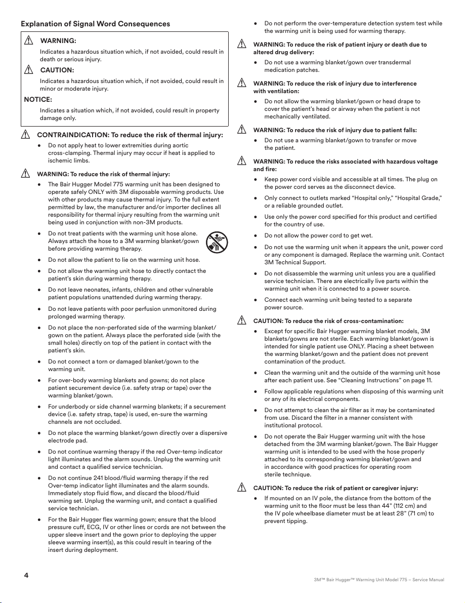
• Do not treat patients with the warming unit hose alone.
Always attach the hose to a 3M warming blanket/gown
before providing warmingtherapy.
• Do not allow the patient to lie on the warming unithose.
• Do not allow the warming unit hose to directly contact the
patient’s skin during warmingtherapy.
• Do not leave neonates, infants, children and other vulnerable
patient populations unattended during warmingtherapy.
• Do not leave patients with poor perfusion unmonitored during
prolonged warmingtherapy.
• Do not place the non-perforated side of the warming blanket/
gown on the patient. Always place the perforated side (with the
small holes) directly on top of the patient in contact with the
patient’sskin.
• Do not connect a torn or damaged blanket/gown to the
warmingunit.
• For over-body warming blankets and gowns; do not place
patient securement device (i.e. safety strap or tape) over the
warmingblanket/gown.
• For underbody or side channel warming blankets; if a securement
device (i.e. safety strap, tape) is used, en-sure the warming
channels are notoccluded.
• Do not place the warming blanket/gown directly over a dispersive
electrodepad.
• Do not continue warming therapy if the red Over-temp indicator
light illuminates and the alarm sounds. Unplug the warming unit
and contact a qualified servicetechnician.
• Do not continue 241blood/fluid warming therapy if the red
Over-temp indicator light illuminates and the alarm sounds.
Immediately stop fluid flow, and discard the blood/fluid
warming set. Unplug the warming unit, and contact a qualified
servicetechnician.
• For the BairHugger flex warming gown; ensure that the blood
pressure cuff, ECG, IV or other lines or cords are not between the
upper sleeve insert and the gown prior to deploying the upper
sleeve warming insert(s), as this could result in tearing of the
insert duringdeployment.
• Do not perform the over-temperature detection system test while
the warming unit is being used for warmingtherapy.
!
WARNING: To reduce the risk of patient injury or death due to
altered drugdelivery:
• Do not use a warming blanket/gown over transdermal
medication patches.
!
WARNING: To reduce the risk of injury due to interference
with ventilation:
• Do not allow the warming blanket/gown or head drape to
cover the patient’s head or airway when the patient is not
mechanicallyventilated.
!
WARNING: To reduce the risk of injury due to patientfalls:
• Do not use a warming blanket/gown to transfer or move
thepatient.
!
WARNING: To reduce the risks associated with hazardous voltage
andfire:
• Keep power cord visible and accessible at all times. The plug on
the power cord serves as the disconnectdevice.
• Only connect to outlets marked “Hospital only,” “Hospital Grade,”
or a reliable groundedoutlet.
• Use only the power cord specified for this product and certified
for the country ofuse.
• Do not allow the power cord to get wet.
• Do not use the warming unit when it appears the unit, power cord
or any component is damaged. Replace the warming unit. Contact
3M TechnicalSupport.
• Do not disassemble the warming unit unless you are a qualified
service technician. There are electrically live parts within the
warming unit when it is connected to a power source.
• Connect each warming unit being tested to a separate
powersource.
!
CAUTION: To reduce the risk of cross‑contamination:
• Except for specific Bair Hugger warming blanket models, 3M
blankets/gowns are not sterile. Each warming blanket/gown is
intended for single patient use ONLY. Placing a sheet between
the warming blanket/gown and the patient does not prevent
contamination of the product.
• Clean the warming unit and the outside of the warming unit hose
after each patient use. See “Cleaning Instructions” on page 11.
• Follow applicable regulations when disposing of this warming unit
or any of its electricalcomponents.
• Do not attempt to clean the air filter as it may be contaminated
from use. Discard the filter in a manner consistent with
institutional protocol.
• Do not operate the BairHugger warming unit with the hose
detached from the 3M warming blanket/gown. The Bair Hugger
warming unit is intended to be used with the hose properly
attached to its corresponding warming blanket/gown and
in accordance with good practices for operating room
steriletechnique.
!
CAUTION: To reduce the risk of patient or caregiverinjury:
• If mounted on an IV pole, the distance from the bottom of the
warming unit to the floor must be less than 44” (112 cm) and
the IV pole wheelbase diameter must be at least 28” (71cm) to
preventtipping.
5
GB / 34-8718-8817-7
!
CAUTION: To reduce the risk of fire:
• 3M warming blankets and gowns are classified as Class I Normal
Flammability as defined by the Consumer Product Safety
Commissions flammable fabric regulation, 16CFR 1610. Follow
standard safety protocols when using high intensity heat sources.
!
CAUTION: To reduce the risks of thermal injury, hyperthermia
or hypothermia:
• 3M recommends continuously monitoring core temperature. In
the absence of continuous monitoring, monitor the temperature
of patients who are incapable of reacting, communicating and/or
who cannot sense temperature a minimum of every 15minutes or
according to institutional protocol.
• Monitor cutaneous responses of patients who are incapable
of reacting, communicating and/or who cannot sense
temperature a minimum of every 15minutes or according to
institutional protocol.
• Adjust air temperature or discontinue warming therapy when
the therapeutic goal is reached, if elevated temperatures are
recorded or if there is an adverse cutaneous response in the
warmed area.
• Do not place the warming unit on a soft uneven surface, such
as a bed, or a visibly wet surface as the air in-take may become
blocked and cause the warming unit to overheat, compromising
the warming unit’sperformance.
• Perform all temperature testing of the warming unit with a 3M
Model 22110 temperature testunit.
!
CAUTION: To reduce the risk associated with electromagnetic
interference (EMI) due to portable and mobile radio frequency (RF)
communicationsequipment:
• The 3M BairHugger temperature management system has
been tested to be resistant to both EMI and electro-static
discharge(ESD).
• Install and put into service the 3M Bair Hugger temperature
management system according to the electromagnetic
compatibility (EMC) information provided in the Guidance and
Manufacturer’sDeclaration.
• Should interference occur, move away from the portable or
mobile RF communicationsequipment.
Notices
1. The Bair Hugger warming unit meets medical electronic interference
requirements. If radio frequency interference with other equipment
should occur, connect the warming unit to a different power source.
2. To avoid warming unitdamage:
• Use proper Electrostatic Discharge (ESD) procedures when
performing maintenance.
• Do not modify this equipment without authorization from
the manufacturer.
• Do not immerse the warming unit, warming unit parts
or accessories in any liquid or subject them to any
sterilizationprocess.
• Do not use cleaning solutions with greater than 80% alcohol or
solvents, including acetone and thinner, to clean the warming unit
or hose. Solvents may damage the labels and other plasticparts.
Proper Use andMaintenance
3M assumes no responsibility for the reliability, performance, or safety of
the warming unit if the following eventsoccur:
• Modifications or repairs are performed by unqualified personnel.
• The warming unit is used in a manner other than that described in
the Operator’s or ServiceManuals.
• The warming unit is installed in an environment that does not
meet the appropriate electrical and groundingrequirements.
• The warming unit not maintained in accordance with the
procedures described in the ServiceManual.
Read Before ServicingEquipment
All repair, calibration, and servicing of the warming unit require the skill
of a qualified, medical equipment service technician who is familiar
with good practice for medical device repair. If service does not require
the manufacturer’s attention, the Model 775 Service Manual provides
the technical information needed to service the warming unit. Perform
all repairs and maintenance in accordance with the instructions in the
Service Manual. For additional service information, please contact 3M
technicalsupport.
SafetyInspection
Perform a safety inspection after making repairs to the warming unit and
before returning the warming unit to service. A safety inspection should
include calibrating the operating temperature settings and testing the
over-temperature detection function as described in this service manual as
well as testing for leakage current and continuity check on safetyground.
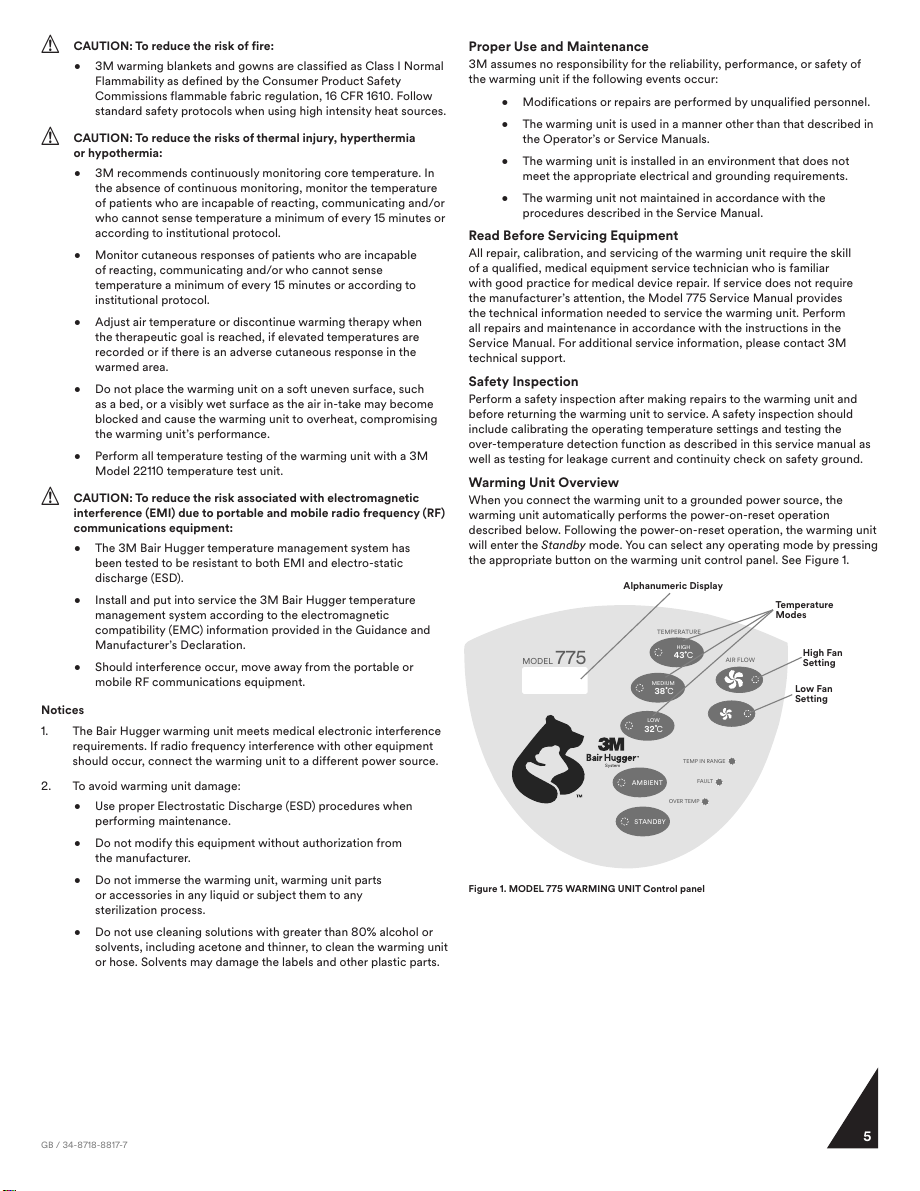
Warming Unit Overview
When you connect the warming unit to a grounded power source, the
warming unit automatically performs the power-on-reset operation
described below. Following the power-on-reset operation, the warming unit
will enter the Standby mode. You can select any operating mode by pressing
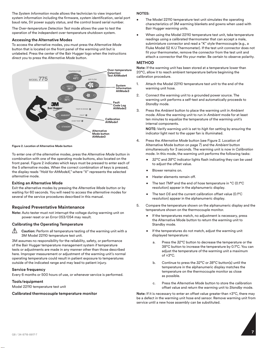
the appropriate button on the warming unit control panel. See Figure 1.
TEMP IN RANGE
FAULT
OVER TEMP
STANDBY
AMBIENT
MODEL 775 43 C
MEDIUM
HIGH
TEMPERATURE
AIR FLOW
38 C
LOW
32 C
System
High Fan
Setting
Alphanumeric Display
Temperature
Modes
Low Fan
Setting
Figure 1. MODEL 775 WARMING UNIT Control panel