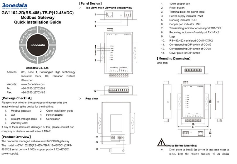
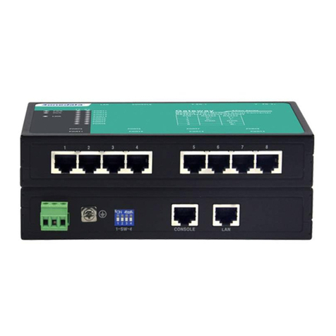
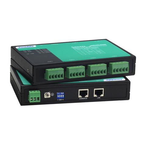
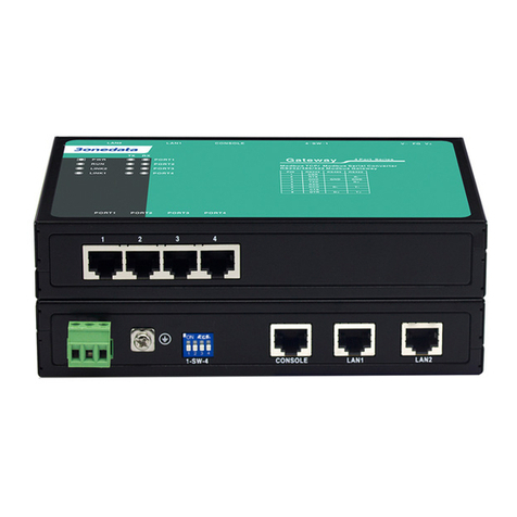
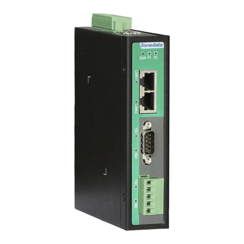
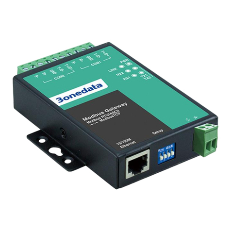
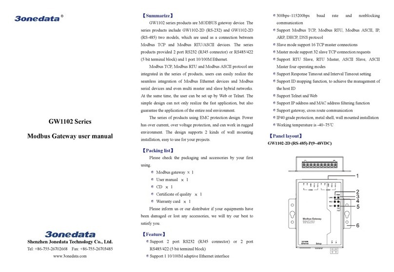
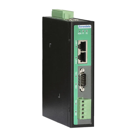
3One data GW11 Series User manual

(I)GW11XX Series
Modbus Gateway
User Manual
Document Version: 03
Publication Date: Oct 24, 2017
Industrial Ethernet communication solutions experts Shenzhen 3onedata Technology Co., Ltd.

Copyright © 2017 3onedata Technology Co., Ltd. All rights reserved.
For this manual, all rights reserved by 3onedata Technology Co., Ltd. No company or individual is
allowed to duplicate or translate this manual in any forms without written permission issued by 3onedata
Technology Co., Ltd.
Trademark statement
, and is the registered trademark owned by
Shenzhen 3onedata Technology Co., Ltd. And other trademarks mentioned in this manual belong to
their corresponding companies.
Conventions Used in the Manual
Technical or printing errors might exist in the product or the instruction manual; therefore, Shenzhen
3onedata Technology Co., Ltd. reserves the right to change the manual entirely or partially with no
advance notice required. 3onedata provides this document as is, without warranty of any kind, either
expressed or implied, including, but not limited to, its particular purpose. Due to the improvement of the
management software, the version of software that you are using might not be the latest or the perfect
version. The manual is only for your reference, and please contact us if you have any questions.

Shenzhen 3onedata Technology Co., Ltd.
Address: 3/B, Zone 1, Baiwangxin High Technology Industrial park, Nanshan District, Shenzhen, 518108 China
Tel: +86-755-26702668
E-mail: sales@3onedata.com
Fax: +86-755-26703485
Website: http://www.3onedata.com

User Manual
3onedata proprietary and confidential 1
Copyright © Shenzhen 3onedata Technology Co., Ltd.
Preface
The user manual describes the Modbus Gateway:
Product features
Product network management configuration
Overview of network management principles
The screenshot reference model for this manual is GW1118-8D (3IN1) Modbus. Other
types of products in addition to supporting the serial type (RS-232, RS-422, RS-485), and
the number of network ports and the number of serial ports are different, the interface
functions and interface operations are the same.
Audience
This manual applies to the following engineers:
Network administrators
Technical support engineers
Hardware engineers
Conventions
Format Description
“ ” Words with the symbol “” mean that those are interface
words. Fox example “Port number”.
> Multiple paths are separated by the symbol ‘>’.
Light blue Font Click light blue font to hyperlink The font color is as follows:
‘Light Blue’.
About This Chapter
The section ‘about this chapter’ provides links to various
sections of this chapter, as well as links to the Principles
Operations Section of this chapter.
Symbols
Format Description

User Manual
3onedata proprietary and confidential 2
Copyright © Shenzhen 3onedata Technology Co., Ltd.
Format Description
Indicates a potentially hazardous situation which, if not
avoided, could result in equipment damage, data loss,
performance deterioration, or unanticipated results.
NOTICE is used to address practices not related to personal
injury.
Ndicates a potentia
lly hazardous situation which, if not
avoided, could result in death or serious injury.
Calls attention to important information, best practices and
tips.
NOTE is used to address information not related to personal
injury, equipment damage, and environment deterioration.
The tips of configuration and operation.
Revision History
Version No. Date Revision note
01 August 14, 2017 Layout Adjustment
02 August 16, 2017 Manual Maintenance
03 October 24,2017 Add dual network ports function

User Manual
3onedata proprietary and confidential I
Copyright © Shenzhen 3onedata Technology Co., Ltd.
Contents
PREFACE ......................................................................................................................................... 1
CONTENTS ....................................................................................................................................... I
OVERVIEW ..................................................................................................................................... 1
PART ONE: OPERATION................................................................................................................ 1
1LOGIN THE WEB INTERFACE ............................................................................................. 1
ABOUT THIS CHAPTER .......................................................................................................... 1
1.1 SYSTEM REQUIREMENTS ........................................................................................... 1
1.2 SET THE IP ADDRESS OF THE COMPUTER...................................................................... 2
1.3 LOGIN THE WEB CONFIGURATION INTERFACE ............................................................. 3
1.4 WEB TIMEOUT PROCESSING ...................................................................................... 4
2OVERVIEW ............................................................................................................................. 5
3NETWORK SETTING ............................................................................................................. 7
4SERIAL SETTINGS ............................................................................................................... 10
ABOUT THIS CHAPTER .........................................................................................................10
4.1 COM SETTINGS.......................................................................................................10
4.2 COM INFORMATION.................................................................................................12
5MODBUS SETTINGS ............................................................................................................ 14
ABOUT THIS CHAPTER .........................................................................................................14
5.1 MODBUS PARAMETERS.............................................................................................14
5.2 SLAVE ID................................................................................................................15
6STATE MONITORING .......................................................................................................... 17
ABOUT THIS CHAPTER .........................................................................................................17
6.1 COM STAT E ............................................................................................................17
7ACCESS CONTROL .............................................................................................................. 19
ABOUT THIS CHAPTER .........................................................................................................19
7.1 DEVICE SECURITY ...................................................................................................19
7.2 IP FILTERING...........................................................................................................20
7.3 MAC FILTERING......................................................................................................22
7.4 USER MANAGEMENT ...............................................................................................23
8SYSTEM MANAGEMENT .................................................................................................... 25
ABOUT THIS CHAPTER .........................................................................................................25
8.1 SYSTEM INFORMATION .............................................................................................25
User Manual
3onedata proprietary and confidential II
Copyright © Shenzhen 3onedata Technology Co., Ltd.
8.2 SYSTEM FILE ..........................................................................................................26
8.3 LOGOUT &REBOOT .................................................................................................28
9WORKING MODE CONFIGURATION ................................................................................ 29
ABOUT THIS CHAPTER .........................................................................................................29
9.1 RTU MASTER MODE ................................................................................................29
9.2 RTU SLAVE MODE...................................................................................................35
9.3 ASCII MASTER MODE .............................................................................................41
9.4 ASCII SLAVE MODE ................................................................................................46
10 CUSTOMER CASE ................................................................................................................ 53
PART TWO: PRINCIPLE .............................................................................................................. 57
11 MODBUS OVERVIEW .......................................................................................................... 57
ABOUT THIS CHAPTER .........................................................................................................57
11.1 PROTOCOL IMPLEMENTATION ....................................................................................57
11.2 MASTER AND SLAVE WORKING STATE DIAGRAM ..........................................................58
11.3 MODBUS COMMUNICATION PRINCIPLE........................................................................59
11.4 TRANSMISSION MODE ..............................................................................................61
11.5 MODBUS BASIC ARCHITECTURE DIAGRAM ..................................................................64
12 MODBUS SETTINGS ............................................................................................................ 66
ABOUT THIS CHAPTER .........................................................................................................66
12.1 MODBUS PARAMETER SETTINGS ................................................................................66
12.2 SLAVE ID MAPPING .................................................................................................68

(I)GW11XX Modbus User Manual
3onedata proprietary and confidential 1
Copyright © Shenzhen 3onedata Technology Co., Ltd.
Overview
Introduction
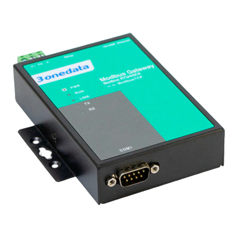
(I)GW11XX is a serial-to-Ethernet Modbus gateway that converts between Modbus
TCP and Modbus RTU/ASCII protocols. It provides several serial ports and 1 or 2
10/100M Ethernet port.
Modbus TCP, Modbus RTU and Modbus ASCII protocol are integrated in the products,
users can easily realize the seamless integration of Modbus Ethernet devices and
Modbus serial devices and even multi master and slave hybrid networks. At the same
time, the user can be set up by Web or Telnet. The simple design can not only realize
the fast application, but also guarantee the application of the entire real industrial
environment.
The products using EMC protection design. Power has over current, over voltage
protection, and can work in rugged environment.
Product Features
Supports multiway serial ports
Supports 1 or 2 10/100M Ethernet port
Supports 1 DC/AC power input
Support 300~115200bps wire-speed non-blocking communication
Support RTU Slave, RTU Master, ASCII Slave and ASCII Master working modes
Support Modbus TCP, Modbus RTU, Modbus ASCII, IP, ARP, DHCP and DNS
protocols
Slave mode support 16 TCP master connections
Master mode support 32 slave TCP connection requests
Support response timeout and interval timeout settings
Support ID mapping function, to achieve the management of the host ID
Support WEB and Telnet configurations
Support IP address and MAC address filtering function
Support cross-gateway and cross-router communication
Provide Windows configuration tools for easy to use, easy to bath install.
No fan, low consumption design, IP30 protection grade

(I)GW11XX Modbus User Manual
3onedata proprietary and confidential 1
Copyright © Shenzhen 3onedata Technology Co., Ltd.
Part One: Operation
1Login the WEB Interface
About This Chapter
Content Hyperlink
This chapter 1.1 System Requirements
1.2 Set the IP address of the Computer
1.3 Login the WEB Configuration Interface
1.4 WEB Timeout Processing
1.1 System Requirements
Using the Modbus Gataway device, the system should meet the following conditions.
Hardware and software System requirements
CPU Pentium 586
Memory 128M above
Resolution 1024x768 or above
Color 256 color or above
Browser Internet Explorer 6.0 or above
Operating system Windows XP
Windows 7

(I)GW11XX Modbus User Manual
3onedata proprietary and confidential 2
Copyright © Shenzhen 3onedata Technology Co., Ltd.
1.2 Set the IP address of the Computer
The default management of the Modbus Gataway device is as follows:
IP Settings Default Values
IP address 192.168.1.254
Subnet mask 255.255.255.0
When configuring a Gataway through the Web:
Before making remote configuration, make sure that the route between the
computer and the Gataway is reachable.
Before making a local configuration, make sure that the IP address of the
computer and the Gataway are on the same subnet.
Note:
When the switch is first configured, if it is configured locally, make sure the current
computer network segment is 1.
IP configuration example
For example, suppose that the IP address of the computer is 192.168.5.60, need to
change the IP address of the network segment "5" to "1"
Operation steps
The steps are as follows:
Step 1 Open “Control panel > Network connection > Local area connection > Properties >
Internet protocol version (TCP/IPv4) Properties”.
Step 2 Change the "5" selected by the red frame in the figure to "1".

(I)GW11XX Modbus User Manual
3onedata proprietary and confidential 3
Copyright © Shenzhen 3onedata Technology Co., Ltd.
Step 3 Click "OK".
Step 4 End.
1.3 Login the WEB Configuration Interface
Operation steps
Log in to the WEB configuration interface as follows:
Step 1 Run the computer browser.
Step 2 Enter the address of the switch "http://192.168.1.254" in the address bar of the
browser.
Step 3 Click the Enter key.
Step 4 Pop-up dialog box as shown below, enter the user name and password in the login
window.

(I)GW11XX Modbus User Manual
3onedata proprietary and confidential 4
Copyright © Shenzhen 3onedata Technology Co., Ltd.
Note:
The default username and password for the Modbus gateway are "admin", which is
strictly case-sensitive when typing.
The default user password is with administrator privileges.
WebServer will provide three opportunities to enter the user name and password. If you
enter the error 3 times in succession, the browser will display "Access denied" to deny
access to the information. Please refresh the page and try again.
Step 5 Click “OK”.
Step 6 End.
After successful login, you can configure the relevant parameters and information of
the WEB interface as needed.
Note:
After logging in to the device, you can modify the IP address of the switch for ease of use.
1.4 WEB Timeout Processing
When the user does not operate for more than 300 seconds in the Web interface, the
system will do the timeout processing:
Keep the configuration of this login;
Logout this login.
Note:
After the system times out, if you need to continue operate in the WEB interface, please
re-login.

(I)GW11XX Modbus User Manual
3onedata proprietary and confidential 5
Copyright © Shenzhen 3onedata Technology Co., Ltd.
2Overview
Function Description
On the “Overview” page, you can view “Basic Settings” and “Network Information”.
Operation Path
Main Menu > Overview
Interface Description
Basic Settings interface screenshot
The main element configuration instructions in the Basic Settings interface.
Interface Elements Description
Name Network mark of the device. It is convenient for
management tools to judge.
Module Network identification.
Description The description of device’s features, like as used key place.
Serial NO. Serial number of the device. It is co
nvenient for device
management.
Hardware version The current hardware version information, please note the
limit of software version to hardware version
Firmware version The current software’s version information, upgrade
software version will have more function

(I)GW11XX Modbus User Manual
3onedata proprietary and confidential 6
Copyright © Shenzhen 3onedata Technology Co., Ltd.
Interface Elements Description
Contact The contact information of person when maintenance the
device, it can be configured in system information.
Number of LANs Display LAN port number of the Gateway device.
Network information interface screenshot
The dual-port device displays the "Lan1" and "Lan2" columns. The single-port device
displays only the "Lan1" column.
Interface Elements Description
IP mode Display how to get an IP Address of the Gateway device.
Subnet mask Display the Subnet mask of the Gateway device.
DNS mode Display how to get a DNS of the Gateway device.
MAC address Hardware address, 48bits(6 bytes,), 16 hexadecimal, it is
unique
IP Address Display the IP Address of the Gateway device.
Gateway Display the Gateway address of the Gateway device.
DNS server Display the DNS server address of the gateway device.

(I)GW11XX Modbus User Manual
3onedata proprietary and confidential 7
Copyright © Shenzhen 3onedata Technology Co., Ltd.
3Network setting
Function Description
On the “Network settings” page, you can configure how to obtain IPv4 addresses.
Operation Path
Main Menu > Network settings
Interface Description
Network settings interface screenshot
The dual-port device displays the "Lan1" and "Lan2" columns. The single-port device
displays only the "Lan1" column.

(I)GW11XX Modbus User Manual
3onedata proprietary and confidential 8
Copyright © Shenzhen 3onedata Technology Co., Ltd.
The main element configuration instructions in the Network settings interface.
Interface
Elements
Description
Default LAN Enable the data from the different network segment of the device
to transmit from the default network port.
Note:
Single-port devices do not support this function。
Lan1 Network port 1 network configuration column.
Note:
The default IP for Lan1 is 192.168.1.254.
The way
to get
the IP address
Use the following IP addresses: Manually configure the IP
address, subnet mask, and default gateway address.
Obtain an IP address automatically: Obtain an IP address,
subnet mask, and default gateway address automatically.

(I)GW11XX Modbus User Manual
3onedata proprietary and confidential 9
Copyright © Shenzhen 3onedata Technology Co., Ltd.
Interface
Elements
Description
IP address Configure the IP address manually in the “IP Address” text box.
Subnet mask Configure the subnet mask manually in the “Subnet mask” text
box.
Gateway
Configure the gateway address manually in the “Gateway
Address” text box.
The way to get
the DNS server
address
Use the following DNS server address: Manually configure
the DNS server address information.
Automatically obtain DNS server address: Automatically
obtain DNS server address information.
Lan2 Network port 2 network configuration column.
Note:
The default IP for Lan1 is 192.168.8.254.
Refer to the corresponding section of Lan1 in this table for the
description of interface elements.
IP Report IP Report configuration column.
Note:
When the Modbus gateway
adopts the "automatic IP address", it
reports the IP address of the user by intermittently, so that the user
knows the new IP address of the Modbus gateway in time.
Sever Address The server that receives the IP address report.
Sever Port The port that sends the IP address report.
Repeat Time The sending frequency of IP report.
When the DHCP server assigns a new IP address to the Modbus gateway, the host
needs to detect the new IP address of the Modbus gateway when the Modbus
gateway is in a network environment that dynamically assigns an IP address. When
the dynamic IP address changes, the Modbus gateway reports its own IP address
to the user by intermittently, so that the user knows the new IP address of the
Modbus gateway in time.

(I)GW11XX Modbus User Manual
3onedata proprietary and confidential 10
Copyright © Shenzhen 3onedata Technology Co., Ltd.
4Serial Settings
About This Chapter
Content Hyperlink
This chapter 4.1 COM Settings
4.2 COM Information
4.1 COM Settings
Function Description
On the “COM settings” page, you can configure basic parameters such as baud rate,
data bit, stop bit and parity bit corresponding to the serial port number. You can also
configure whether the corresponding serial number is enabled for FIFO function, RTS
control, DTR control and Packing length and other advanced parameter information.
Operation Path
Open “Main Menu > Serial Settings > COM Settings” in sequence
Interface Description
COM settings interface screenshot

(I)GW11XX Modbus User Manual
3onedata proprietary and confidential 11
Copyright © Shenzhen 3onedata Technology Co., Ltd.
The main elements configuration instructions in COM settings
Interface Elements Description
Port Select the serial number of the device.
Alias Enter the alias for the corresponding serial number in the
“Alias” text box.
Baud Rate Select the baud rate for the corresponding serial number.
The options are:
300/600/1200/2400/4800/9600/19200/38400/57600/115200
Data Bits Select the data bit for the corresponding serial number. The
options are:
7 bits
8 bits
Stop Bits Select the stop bit for the corresponding serial number. The
options are:
1 bits
2 bits
Parity Bits Select the parity bit
for the corresponding serial number.
The options are:
None
Odd
Even
Mark
Space

(I)GW11XX Modbus User Manual
3onedata proprietary and confidential 12
Copyright © Shenzhen 3onedata Technology Co., Ltd.
Interface Elements Description
Flow Control
Flow control is used in two data transmission speed of
different devices in the control of data flow technology to
ensure that two devices communicate with each other to
avoid data loss. Click the "flow control" drop-down list box,
select the flow control parameters, the options are:
No
RTS/CTS
XON/XOFF
DTR/DSR
Work mode By hardware and software jointly decided, there are three
modes:
RS-232
RS-485
RS-422
Note:
Different types of products support different types of serial ports.
RTSCtrl RTS pin can be controlled, the options are:
AUTO
Force ON
Force OFF
DTRCtrl DTR pin can be controlled, the options are:
AUTO
Force ON
Force OFF
Apply to all Port Check the “Apply to all port” check box to apply the current
settings to all serial ports.
4.2 COM Information
Function Description
On the "COM Information" page, you can view parameter information such as serial
number, alias, baud rate, data bit, stop bit, parity bit and flow control.
Operation Path
Open "Main Menu > Serial Settings> COM Information" in sequence
This manual suits for next models
1
Table of contents
Other 3One data Gateway manuals

3One data
3One data GW11X8-8D (3IN1)-RJ45 Series User manual

3One data
3One data GW1102-2DRS-485-TB-P User manual

3One data
3One data GW1101 Series User manual

3One data
3One data GW1104 Series User manual

3One data
3One data GW1114 Series User manual

3One data
3One data GW1102 Series User manual

3One data
3One data GW1102 Series User manual

3One data
3One data GW1118 Series User manual

3One data
3One data GW1101-1DI(3IN1)-DB-P(12-48VDC) User manual

3One data
3One data IGW1111-3IN1-DB User manual