manuals.online logo
Brands
  1. Home
  2. •
  3. Brands
  4. •
  5. 3One data
  6. •
  7. Gateway
  8. •
  9. 3One data GW1104 Series User manual

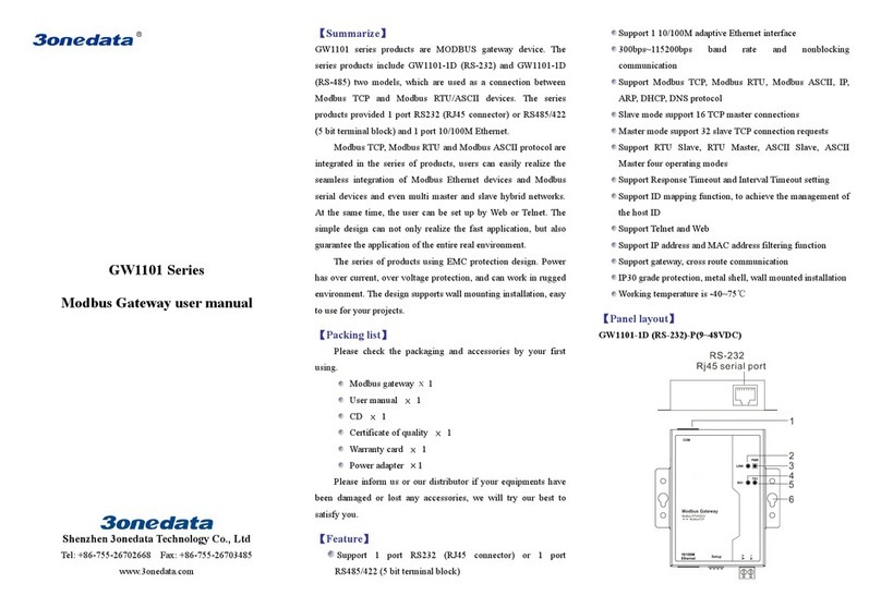
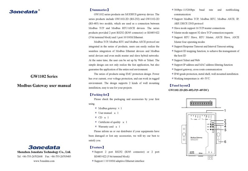
3One data GW1104 Series User manual

GW1104 Series
Modbus Gateway
Quick Installation Guide
3onedata Co., Ltd.
Address: 3/B, Zone 1, Baiwangxin
High Technology
Industrial Park, Song Bai Road, Nanshan
District, Shenzhen, 518108, China
Website:
www.3onedata.com
Tel:
+86 0755-26702688
Fax:
+86 0755-26703485
【Package Checklist】
Please check whether the package and accessories are intact
while using the device for the first time.
1
Modbus gateway × 1
2
Quick installation guide
3
CD
4
Lugs
5
Power adapter
6
Certification
7
Warranty card
If any of these items are damaged or lost, please contact our
company or dealers, we will solve it ASAP.
【Product Overview】
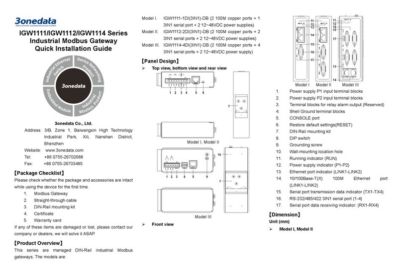
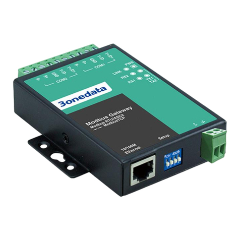
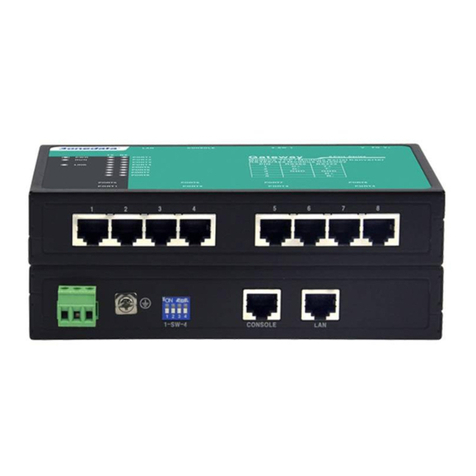
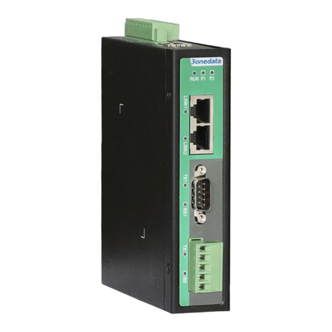
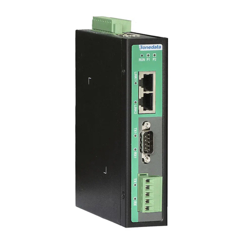
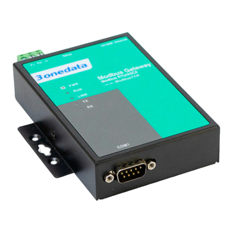
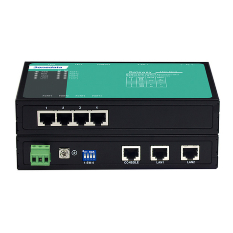
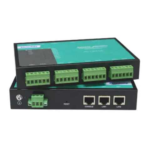
The series products are MODBUS gateway devices. Models
are as follows:
Model I GW 11 04 -4D(RS-232) (4 RS-232 serial ports + 1
100M copper port)
Model II GW 11 04 -4D(3IN1) (4 RS-485/422/232 serial ports
+ 1 100M copper port)
Model III GW 11 04 -4DI(RS-485) (4 RS-485/422 serial port
with isolation + 1 100M copper port)
【Panel Design】
Front View
Model I
Model II Model III
Rear View
Model I
Model II
Model III
Top view
Model II
Model III
Bottom View
Model I
Model II Model III
Left view, right view
Model I
Model II Model III
1. 10/100Base-T(X) Ethernet port
2. Restoring factory setting button
3. Serial port transmission data indicators
4. Serial port receiving data indicators
5. Copper port connection indicator
6. Running status indicator
7. Power indicator
8. Terminal block 1 for power input
9. Grounding screw
10. DIP switch
11. Console Port
12. RS-232 serial port
13. Terminal block 2 for power input
14. RS-485/422/232 serial port
15. RS-485/422 serial port
16. Foot pad
17. Mounting
18. Wall-mounting location hole
【Mounting Dimension】
Unit: mm
Model I
Model II Model III
Note Before Mounting:
Don't place or install the device in area near water or
moist, keep the relative humidity of the device
surrounding between 5%~95% without condensation.
Before power on, first confirm the supported power
supply specification to avoid over-voltage damaging the
device.
The device surface temperature is high after running;
please don't directly contact to avoid scalding.
【
Wall-mounted Device Mounting
】

Model I
Step 1 Adopt M3 screw to install the left/right mounting
board on the device backboard.
Step 2 Place the device on the wall as reference or
reference installation dimension; mark 2 bolt
positions on the wall.
Step 3 Attach the equipment to the marked wall and
tighten it with M4 screws to the marked position.
Mounting ends.
Model II Model III
Step 1 Adopt M3 screw to install the left/right mounting
board on the device backboard.
Step 2 Place the device on the wall as reference or
reference installation dimension; mark 2 bolt
positions on the wall.
Step 3 Nail M4 screws on the wall and keep 2mm
interspace reserved.
Step 4 Hang the device on two screws and slide
downward, then tighten the screw to enhance
stability, mounting ends.
【Wall-mounted Device Disassembling】
Step 1 Device power off.
Step 2 Unscrew the screw on the wall about 2mm.
Step 3 Lift the device upward slightly; take out the device,
disassembling ends.
Note before powering on:
Power ON operation: First insert the power supply
terminal block into the device power supply interface,
and then plug the power supply plug contact and power
on.
Power OFF operation: first unpin the power plug, then
remove the power line, please note the operation order
above.
【Power Supply Connection】
9~48VDC power supply
Model I of this series provides 2-pin 5.08mm pitch
terminal block, power supply range: 9~48VDC.
12~48VDC power supply
The model II and model III of this series provide
3-Pin 5.08mm pitch terminal blocks, in which V+
and V- are DC power input, FG is the power
grounding input; The power supply supports non-polarity,
power supply range: 12~48VDC.
【DIP Switch Settings】
The model II and model III of this series provide
4-bits DIP switch for function setting, where "ON" is
enable valid terminal. The device needs to be powered on
again to change the status of DIP switch.
DIP switches definition as follows:
DIP
Definition
Operation
1
Reserved
-
2 Restore factory
defaults
Set the DIP switch to ON,
power on the device again, it
will restore to factory settings,
then turn off the DIP switch.
3
Reserved
-
4
Reserved
-
【Serial Port Connection】
RS-232 Interface
The model I of this series provides RS-232 port,
adopts RJ45 connector. The PIN definition are
as follows.
PIN 1 2 3 4 5. 6 7 8
RS-232
TXD
RXD
RTS
CTS
DSR
GND
DTR
DCD
3IN1 Interface
The model II of this series provides 3IN1 serial
port, which supports RS232, RS485 and RS422
at the same time. The interface type is RJ45 and its pin
definitions are as follows:
PIN 1 2 3 4 5. 6 7 8
RS-232
DSR
RTS
GND
TXD
RXD
DCD
CTS
DTR
RS-485
—
—
GND
—
—
D-
—
D+
RS-422
—
R-
GND
R+
—
T-
—
T+
RS-485/ 422 interface
The model III of this series provides 5-Pin
5.08mm pitch industrial terminal blocks.
The serial port is isolated and its pin
definitions are as follows:
PIN 1 2 3 4 5.
RS-485 D+ D- GND — —
RS-422 T+ T- GND R+ R-
【Checking LED Indicator】
The device provides LED indicators to monitor the device
working status with a comprehensive simplified
troubleshooting; the function of each LED is described in the
table as below:
LED Indicate Description
PWR
ON PWR is connected and running
normally
OFF PWR is disconnected and running
abnormally
RUN
Blinking System runs normally
OFF The system is not running or running
abnormally
ON System is running abnormally
LINK
ON Copper port has established an
active network connection.
Blinking Copper port is in a network activity
state.
OFF Copper port has not established an
active network connection.
1 8
LED Indicate Description
TX(1-4)
OFF
No data or abnormal data is being
transmitted through serial port.
Blinking Serial port is transmitting data.
RX(1-4)
OFF
Serial port is not receiving data or
receiving data abnormally
Blinking Serial port is receiving data.
【
Logging in to WEB Interface
】
This device supports WEB management and configuration.
Computer can access the device via Ethernet interface. The
way of logging in to device’s configuration interface via IE
browser is shown as below:
Step 1 Configure the IP addresses of computer and the
device to the same network segment, and the
network between them can be mutually accessed
Step 2 Enter device’s IP address in the address bar of the
computer browser.
Step 3 Enter device’s user name and password in the
login window as shown below.
Step 4 Click “OK” button to login to the WEB interface of
the device.
Notes:
The default IP address of the device Internet access is
“192.168.1.254”.
The default user name and password of the device are
“admin”.
If the username or password is lost, user can restore it to
factory settings via device DIP switch or management
software; all modified configurations will be cleared
after restoring to factory settings, so please backup
configuration file in advance.
Please refer to user manual for specific configuration
method of logging in to WEB interface and other
configurations about network management function.
【Specification】
Panel
100M Copper Port 10/100Base-T(X) self-adapting
RJ45 port
Serial Port
3IN1 RJ45 interface,
RS-
485/422 terminal blocks
with isolation or RS-232 RJ45
interface
Indicator
Power indicator, Running
indicator, Copper port
connection indicator, Serial port
transmission and receiving data
indicator
Power supply
Input power supply 9~48VDC or 12~48VDC
Access terminal block 2-Pin or 3-
pin 5.08mm pitch
terminal blocks
Power consumption
No-load 2.94W@12VDC
Full-load 3.00W@12VDC
Working environment
Working temperature -40~75℃
Storage temperature -40~85℃
Working humidity 5%~95% (no condensation)
Protection grade IP30(metal)

This manual suits for next models

2

Other 3One data Gateway manuals

3One data GW11X8-8D (3IN1)-RJ45 Series User manual

3One data

3One data GW11X8-8D (3IN1)-RJ45 Series User manual

3One data GW1101-1DI(3IN1)-DB-P(12-48VDC) User manual

3One data

3One data GW1101-1DI(3IN1)-DB-P(12-48VDC) User manual

3One data GW1118 Series User manual

3One data

3One data GW1118 Series User manual

3One data GW110X Series User manual

3One data

3One data GW110X Series User manual

3One data GW1102 Series User manual

3One data

3One data GW1102 Series User manual

3One data IGW1111 Series User manual

3One data

3One data IGW1111 Series User manual

3One data GW11 Series User manual

3One data

3One data GW11 Series User manual

3One data IGW1111 Series User manual

3One data

3One data IGW1111 Series User manual

3One data GW1114 Series User manual

3One data

3One data GW1114 Series User manual

3One data GW1101 series User manual

3One data

3One data GW1101 series User manual

3One data GW1102 Series User manual

3One data

3One data GW1102 Series User manual

3One data IGW1111-3IN1-DB User manual

3One data

3One data IGW1111-3IN1-DB User manual

3One data GW1101 Series User manual

3One data

3One data GW1101 Series User manual

3One data GW1102-2DRS-485-TB-P User manual

3One data

3One data GW1102-2DRS-485-TB-P User manual

3One data GW1108 Series User manual

3One data

3One data GW1108 Series User manual

3One data GW110X Series User manual

3One data

3One data GW110X Series User manual

Popular Gateway manuals by other brands

Bpt HAC/200 installation instructions

Bpt

Bpt HAC/200 installation instructions

IntesisBox HS-AC-KNX-16/64 Installation sheet

IntesisBox

IntesisBox HS-AC-KNX-16/64 Installation sheet

Entel GW-UNI Quick start user guide

Entel

Entel GW-UNI Quick start user guide

Anybus X-gateway user manual

Anybus

Anybus X-gateway user manual

Verizon FSNO21VA user guide

Verizon

Verizon FSNO21VA user guide

Far south networks Com.X Administrator's guide

Far south networks

Far south networks Com.X Administrator's guide

Gree VRF Service manual

Gree

Gree VRF Service manual

Patton SmartNode 4131 user manual

Patton

Patton SmartNode 4131 user manual

Huawei HG533 user guide

Huawei

Huawei HG533 user guide

AMX NXR-ZRP quick start guide

AMX

AMX NXR-ZRP quick start guide

RTA 460MCBM-NNA1 Product user guide

RTA

RTA 460MCBM-NNA1 Product user guide

H3C VG 20-16 Compliance and Safety Manual

H3C

H3C VG 20-16 Compliance and Safety Manual

BAB TECHNOLOGIE EIBPORT V3 Firmware update procedure

BAB TECHNOLOGIE

BAB TECHNOLOGIE EIBPORT V3 Firmware update procedure

Lenze x750 manual

Lenze

Lenze x750 manual

RTA 460BCDFM-NNA1 Product user guide

RTA

RTA 460BCDFM-NNA1 Product user guide

ICC XLTR-1000 instruction manual

ICC

ICC XLTR-1000 instruction manual

Atop PG5901B Series Configuration manual

Atop

Atop PG5901B Series Configuration manual

PowerLogic EGX400 Instruction bulletin

PowerLogic

PowerLogic EGX400 Instruction bulletin

manuals.online logo
manuals.online logoBrands
  • About & Mission
  • Contact us
  • Privacy Policy
  • Terms and Conditions

Copyright 2025 Manuals.Online. All Rights Reserved.