Table of Contents
1
Introduction 5
1.1
Features ................................................................................................ 5
1.2
Specifications ( ardware) ..................................................................... 5
1.3
Specifications (Software) ....................................................................... 7
1.4
GNSS / IMU Specification ..................................................................... 8
1.5
Packing List ........................................................................................... 9
1.6
Optional Accessory ............................................................................... 9
1.7
Cellular Module Parameters .................................................................. 9
2
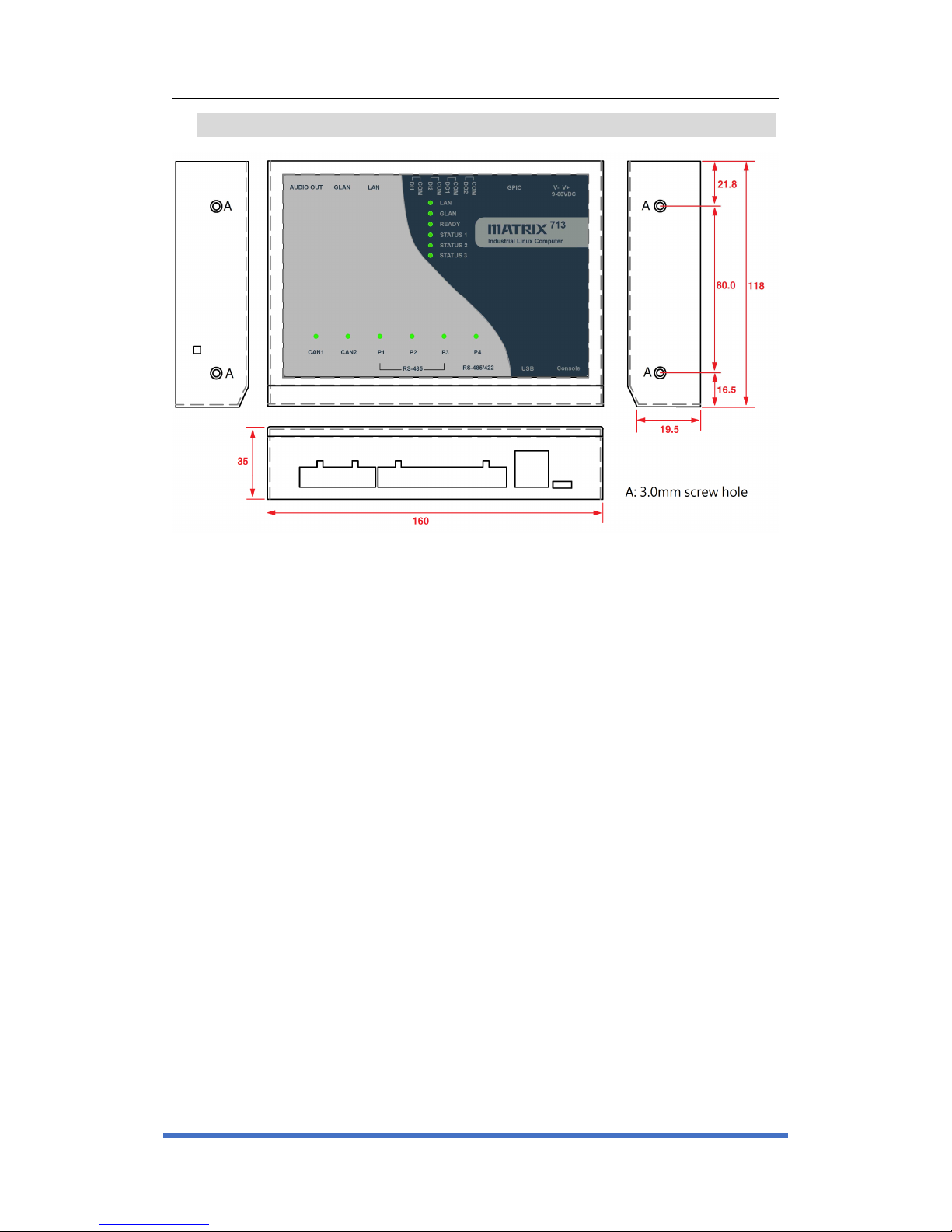
Layout 10
3
Pin Assignment and Definitions 11
3.1
Multi-function Reset Button ................................................................... 11
3.2
LED Indicators ....................................................................................... 12
3.3
CAN Bus Port ........................................................................................ 13
3.4
Serial Port ............................................................................................. 14
3.4.1
RS-485/RS422 Selection (JP4 & J8) ..................................................... 14
3.4.2
Pin assignment of RS-485/RS422 ......................................................... 15
3.4.3
Enable/Disable Termination resistor for RS-485 .................................... 15
3.5
USB Port ............................................................................................... 16
3.6
Serial Console Port ............................................................................... 16
3.7
Audio Port ............................................................................................. 16
3.8
Ethernet LAN Port ................................................................................. 16
3.9
Digital Input ........................................................................................... 17
3.10
Digital Out ............................................................................................. 17
3.11
GPIO ..................................................................................................... 17
3.12
Power Connector................................................................................... 17
3.13
miniPCIe socket .................................................................................... 18
3.14
Micro-SIM socket................................................................................... 18
3.15
SD card socket ...................................................................................... 19