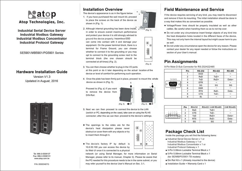
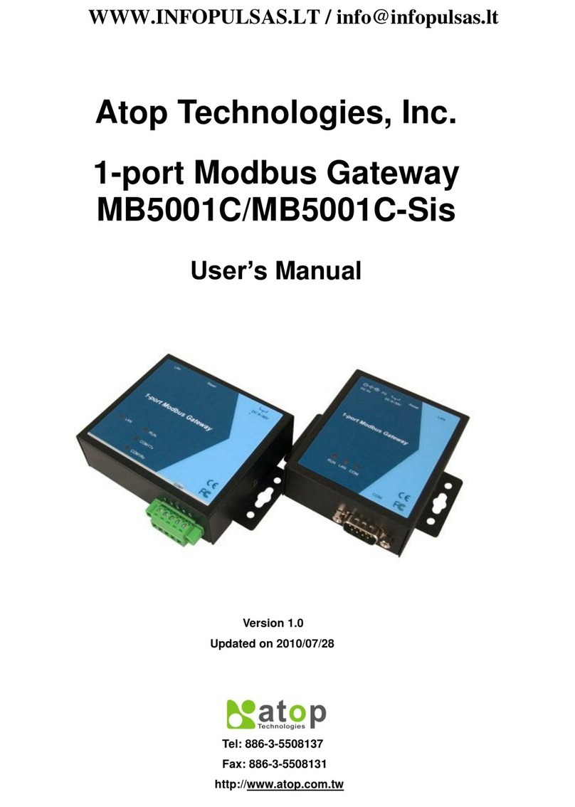
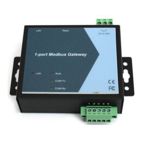
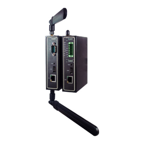
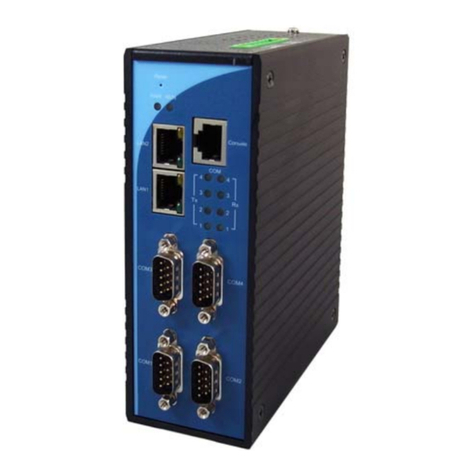
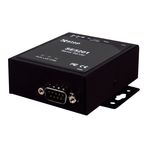
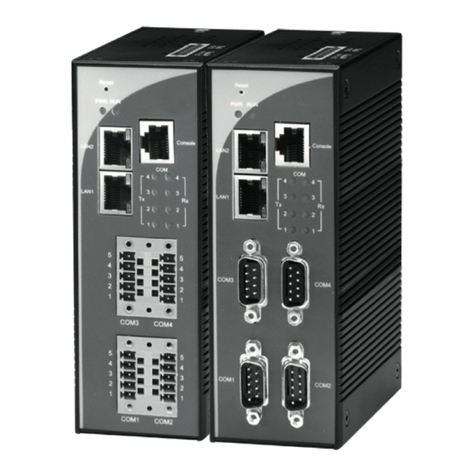
Atop PG5901B Series Instruction sheet

Protocol Gateway
IEC60870-5-101 Master/Slave
IEC60870-5-104 Client/Server
Protocol and
eNode Designer configuration
eNode Configuration Manual
V1.4
August 3rd, 2023
ATOP Technologies, Inc.

IEC 60870-5-101/104
Client and Server
User Manual
CLIENT/SERVER
Page 2 of 83
This PDF Document contains internal hyperlinks for ease of navigation.
For example, click on any item listed in the Table of Contents to go to that page.
IEC 60870-5-101 Configuration Guide
IEC 60870-5-104 Configuration Guide
IEC 60870-5-101 Interoperability
IEC 60870-5-104 Interoperability
Published by:
ATOP Technologies, Inc.
2F, No. 146, Sec. 1, Dongxing Rd.,
Zhubei City, Hsinchu County,
302058, Taiwan, R.O.C.
Tel: +886-3-550-8137
Fax: +886-3-550-8131
https://www.atoponline.com

IEC 60870-5-101/104
Client and Server
User Manual
Page 3 of 83
Important Announcement
Copyright
© 2005-2023 SystemCORP
© 2016-2023 ATOP Technologies, Inc.
The information contained in this document is the property of ATOP technologies, Inc., and is supplied for the sole
purpose of operation and maintenance of ATOP Technologies, Inc., products.
No part of this publication is to be used for any other purposes, and it is not to be reproduced, copied, disclosed,
transmitted, stored in a retrieval system, or translated into any human or computer language, in any form, by any
means, in whole or in part, without the prior explicit written consent of ATOP Technologies, Inc.,
Offenders will be held liable for damages and prosecution.
All rights, including rights created by patent grant or registration of a utility model or design, are reserved.
Disclaimer
We have checked the contents of this manual for agreement with the hardware and the software described. Since
deviations cannot be precluded entirely, we cannot guarantee full agreement. However, the data in this manual is
reviewed regularly and any necessary corrections will be included in subsequent editions.
Suggestions for improvement are welcome.
All other product’s names referenced herein are registered trademarks of their respective companies.
Documentation Control
Author:
Simon Huang
Revision:
1.4 update
Revision History:
Update copyright and ATOP contact information
Creation Date:
31 August 2016
Last Revision Date:
3 August 2023
Reviewer
Simon Huang
Product Reference:
PG59XX Protocol Gateway
Document Status:
Released

IEC 60870-5-101/104
Client and Server
User Manual
Page 4 of 83
Table of Contents
1Introduction .....................................................................................................................7
1.1 Scope ....................................................................................................................................................7
1.2 Overview................................................................................................................................................7
1.2.1 Document Reference ...........................................................................................................7
1.2.2 List of Abbreviations ............................................................................................................8
2General Description .........................................................................................................9
2.1 Adding the IEC 60870-5-101/104 ADH Application ..............................................................................9
3IEC 60870-5-101 Configuration Guide............................................................................10
3.1 IEC 60870-5-101 Client configuration.................................................................................................10
3.1.1 IEC 60870-5-101 Client Settings ........................................................................................11
3.1.1.1 Polling Interval (ms) ......................................................................................................11
3.1.1.2 Link Layer Timeout (ms)................................................................................................11
3.1.1.3 General Interrogation Interval (ms) ...............................................................................11
3.1.1.4 Counter Interrogation Interval (ms) ...............................................................................11
3.1.1.5 Clock Sync Period (ms) .................................................................................................12
3.1.1.6 Command Timeout (ms) ...............................................................................................12
3.1.2 IEC 60870-5-101 Client, Remote IED Tab Layout and Address Settings ............................13
3.1.2.1 Link Address ..................................................................................................................13
3.1.2.2 ASDU Address ...............................................................................................................13
3.1.3 IEC 60870-5-101 Remote IED Data Point List ....................................................................14
3.1.3.1 Adding Data Points........................................................................................................15
3.1.4 IEC 60870-5-101 Remote IED Command List ....................................................................15
3.1.4.1 Adding Commands ........................................................................................................16
3.1.5 IEC 60870-5-101 Remote IED Data Point and Command Parameters...............................17
3.1.5.1 Tag.................................................................................................................................17
3.1.5.2 Data Type.......................................................................................................................17
3.1.5.3 Time Stamp ...................................................................................................................17
3.1.5.4 Start IOA ........................................................................................................................17
3.1.5.5 Count .............................................................................................................................17
3.1.5.6 Operation Mode .............................................................................................................18
3.2 IEC 60870-5-101 Server Configuration...............................................................................................19
3.2.1 IEC 60870-5-101 Server Settings .......................................................................................20
3.2.1.1 Link Address ..................................................................................................................20
3.2.1.2 ASDU Address ...............................................................................................................20
3.2.1.3 Command Timeout (ms) ...............................................................................................20
3.2.1.4 Positive Acknowledgment .............................................................................................20
3.2.1.5 Negative Acknowledgment............................................................................................20
3.2.1.6 Class 1 Event Buffer Size...............................................................................................21
3.2.1.7 Class 1 Event Buffer Size over % ...................................................................................21
3.2.1.8 Class 2 Event Buffer Size...............................................................................................21
3.2.1.9 Class 2 Event Buffer Size over % ...................................................................................21
3.2.1.10 Command Response ACTTERM used ..........................................................................21
3.2.2 IEC 60870-5-101 Server Tab Layout and Address Settings ...............................................22
3.2.3 IEC 60870-5-101 Server Data Point and Command Reference List ...................................23
3.2.3.1 Adding Data Point and Command References ..............................................................23
3.3 IEC 60870-5-101 Common Settings ...................................................................................................25
3.3.1.1 Link Address Size ..........................................................................................................25
3.3.1.2 ASDU Address Size........................................................................................................25
3.3.1.3 Information Object Address Size...................................................................................25
3.3.1.4 Cause of Transmission Size ..........................................................................................25

IEC 60870-5-101/104
Client and Server
User Manual
Page 5 of 83
3.3.1.5 Data Link Transmission Mode.......................................................................................25
4IEC 60870-5-104 Configuration Guide............................................................................27
4.1 IEC 60870-5-104 Client configuration.................................................................................................27
4.1.1 IEC 60870-5-104 Client Settings ........................................................................................28
4.1.1.1 General Interrogation (ms) ...........................................................................................28
4.1.1.2 Interrogation for Group X (ms) ......................................................................................28
4.1.1.3 Request Counter General for Group X (ms) ...................................................................28
4.1.1.4 Command Timeout (ms) ...............................................................................................28
4.1.1.5 Interrogation Intervals (ms)...........................................................................................29
4.1.2 IEC 60870-5-104 Client, Remote IED Tab Layout and Address Settings.........................30
4.1.2.1 ASDU Address ...............................................................................................................30
4.1.2.2 IP Address .....................................................................................................................30
4.1.2.3 TCP Port ........................................................................................................................30
4.1.3 IEC 60870-5-104 Remote IED Data point list......................................................................31
4.1.3.1 Adding Data Points........................................................................................................32
4.1.4 IEC 60870-5-104 Remote IED Commands List ..................................................................33
4.1.4.1 Adding Commands ........................................................................................................34
4.1.5 IEC 60870-5-104 Remote IED Data Point and Command Parameters...............................35
4.1.5.1 Tag.................................................................................................................................35
4.1.5.2 Data Type.......................................................................................................................35
4.1.5.3 Time Stamp ...................................................................................................................35
4.1.5.4 Start IOA ........................................................................................................................35
4.1.5.5 Count .............................................................................................................................35
4.1.5.6 Operation Mode .............................................................................................................35
4.2 IEC 60870-5-104 Server configuration................................................................................................37
4.2.1 IEC 60870-5-104 Server Settings .......................................................................................38
4.2.1.1 ASDU Address ...............................................................................................................38
4.2.1.2 Max ADPU size ..............................................................................................................38
4.2.1.3 Event Buffer Size ...........................................................................................................38
4.2.1.4 TCP Port ........................................................................................................................38
4.2.1.5 Command Timeout (ms) ...............................................................................................38
4.2.1.6 Limitation of Connections .............................................................................................38
4.2.2 IEC 60870-5-104 Server Tab Layout and Address Settings ...............................................39
4.2.3 IEC 60870-5-104 Server Data point and Command Reference list ....................................40
4.2.3.1 Adding Data Point and Command References ..............................................................41
4.3 IEC 60870-5-104 Common Settings ...................................................................................................42
4.3.1.1 K Value...........................................................................................................................42
4.3.1.2 w Value ..........................................................................................................................42
4.3.1.3 t0 Value (s) –Connection Establishment Timeout........................................................42
4.3.1.4 t1 Value (s) –Send or Test APDU Timeout ...................................................................42
4.3.1.5 t2 Value (s) –Acknowledgement Timeout ....................................................................42
4.3.1.6 t3 Value (s) –Idle State Test Frame Timeout ...............................................................43
4.3.1.7 Clock Sync Period (ms) (Client only) .............................................................................43
4.3.1.8 Command Response ACTTERM used (Sever only) .......................................................43
5Using Auto-increment....................................................................................................44
6IEC 60870-5-101 Interoperability....................................................................................45
6.1 System or device.................................................................................................................................45
6.2 Network configuration..........................................................................................................................45
6.3 Physical layer ......................................................................................................................................45
6.4 Link layer.............................................................................................................................................47
6.5 Application layer..................................................................................................................................48
6.6 Basic application functions..................................................................................................................54
7IEC 60870-5-104 Interoperability....................................................................................58
IEC 60870-5-101/104
Client and Server
User Manual
Page 6 of 83
7.1 Protocol overview................................................................................................................................58

7.1.1 ISO/OSI model of IEC 60870-5-104....................................................................................58
7.2 Interoperability: IEC 60870-5-104 Client.............................................................................................58
7.2.1 System or device................................................................................................................59
7.2.2 Link layer............................................................................................................................59
7.2.3 Application layer ................................................................................................................60
7.2.4 Selection of standard ASDUs.............................................................................................61
7.2.5 Basic application functions ...............................................................................................66
7.3 Interoperability: IEC 60870-5-104 Server............................................................................................70
7.3.1 System or device................................................................................................................70
7.3.2 Link layer............................................................................................................................70
7.3.3 Application layer ................................................................................................................72
7.3.4 Selection of standard ASDUs.............................................................................................73
7.3.5 Basic application functions ...............................................................................................78
Table of Figures
Figure 2-1 –Adding an IEC 60870-5-101/104 ADH Application................................................................................9
Figure 3-1 –Configuration Settings for the IEC 60870-5-101 Client. ......................................................................10
Figure 3-2 –Remote IED configuration settings for an IEC 60870-5-101 Client.....................................................13
Figure 3-3 –Data Point configuration options for the IEC 60870-5-101 Client........................................................14
Figure 3-4 –Adding Data Points to an IEC 60870-5-101 Remote IED....................................................................15
Figure 3-5 –Command configuration options for IEC 60870-5-101 Client.......................................................16
Figure 3-6 –Adding Commands to an IEC 60870-5-101 ADH Application Client Remote IED..............................16
Figure 3-7 –Configuration settings for a local IEC 60870-5-101 Server.................................................................19
Figure 3-8 –IED configuration settings for IEC 60870-5-101 Server......................................................................22
Figure 3-10 –Adding Data Point and Command References to an IEC 60780-5-101 Server................................24
Figure 4-1 –Configuration Settings for the IEC 60870-5-104 Client. ......................................................................27
Figure 4-2 - Client Interrogation Intervals.................................................................................................................29
Figure 4-3 –IED configuration settings for an IEC 60870-5-104 Client...................................................................30
Figure 4-4 –Remote IED Data Point configuration options for an IEC 60870-5-104 Client............................31
Figure 4-5 –Adding Data Points to an IEC 60870-5-104 Client..............................................................................32
Figure 4-6 –Command configuration options for an IEC 60870-5-104 Client. ................................................33
Figure 4-7 –Adding Commands to an IEC 60870-5-104 Client. .............................................................................34
Figure 4-8 –Server configuration settings for the IEC 60870-5-104 server............................................................37
Figure 4-9 –IED configuration settings for an IEC 60870-5-104 Server. ................................................................39
Figure 4-11 –Adding Data Point and Command References to an IEC 60780-5-104 Server................................41
Figure 5-1 –Using Auto Increment when adding Data Points or Commands. ........................................................44

IEC 60870-5-101/104
Client and Server
User Manual
Page 7 of 83
1Introduction
Thank you for Buying ATOP’s Protocol Gateway.
The product is bundled with the following three user manuals:
1) Hardware specific installation user manual, not covered in this document. It covers ATOP’s hardware
installation procedure, wiring, power connection etc.
2) Getting started with ATOP’s Protocol Gateway user manual – configuration tool introduction, web
configuration, software architecture introduction–not covered in this document. This manual covers the
introduction, installation, network set-up maintenance and using of the configuration tool software,
including the procedure to be followed for uploading new configurations to ATOP’s device.
3) Protocol specific user manual (This Manual). One protocol-specific manual will be provided for each
protocol installed on the device. This manual covers:
a. Basic device network configuration
b. Step-by-step protocol set-up for in eNode designer
c. Description of the protocol-specific software features, the device profile and the implementation
table of supported functionalities.
This manual is for IEC-60870-5-101 and IEC-60870-5-104 client server and describes how to use the IEC-60870-
5-101/104 eNode Designer Module to configure ATOP’s IEC 60870-5-101/103 ADH Application within the eNode
Designer configuration tool.
1.1 Scope
This document is divided into 5 major sections:
•Overview with General Description; and a
•IEC 60870-5-101 Configuration Guide
•IEC 60870-5-104 Configuration Guide
•IEC 60870-5-101 Interoperability
•IEC 60870-5-104 Interoperability
1.2 Overview
1.2.1 Document Reference
[1] Document Title: Getting started with ATOP’s Protocol Gateways
Revision: Version 1.00 or higher
[2] Document Title: IEC 60870-5-101 standard
Revision: Edition 2 –02/2003
[3] Document Title: IEC 60870-5-104 standard
Revision: Edition 2 –06/2006

IEC 60870-5-101/104
Client and Server
User Manual
Page 8 of 83
1.2.2 List of Abbreviations
ASDU = Application Service Data Unit
ADH = Application Data Hub
IEC = International Electrical Commission
IED = Intelligent Electronic Device
PLC = Programmable Logic Controller

IEC 60870-5-101/104
Client and Server
User Manual
Page 9 of 83
1
2
3
4
5
6
Figure 2-1 –Adding an IEC 60870-5-101/104 ADH Application.
2General Description
2.1 Adding the IEC 60870-5-101/104 ADH Application
An IEC 60870-5-101/104 ADH application can be set up as a Client or a Server. This choice will be presented when
adding the application. Please note that ATOP Protocol gateways supports one Server application per protocol
per device.
Right click the intended port for the IEC 60870-5-101/104 ADH application.
Left click Add ADH Application.
Left click IEC 60870-5-101 or IEC 60870-5-104. eNode Designer will automatically choose between IEC
60870-5-101 or IEC 60870-5-104 depending on what type of port the application is being added to.
This dialogue box will appear, asking whether the new application is to be configured as a Client or a Server.
Select either Client or Server from the drop down menu.
Left click OK to add the application.
There are differences when configuring the new ADH application depending on whether it is an IEC 60870-5-101 or
104 and whether or not it is configured as a Server or a Client. See the following links for specific configuration
information:
IEC 60870-5-101 Client configuration
IEC 60870-5-101 Server configuration
IEC 60870-5-104 Client configuration
IEC 60870-5-104 Server configuration
1
2
3
4
5
6

IEC 60870-5-101/104
Client and Server
User Manual
Page 10 of 83
1
2
3
4
3IEC 60870-5-101Configuration Guide
3.1 IEC 60870-5-101 Client configuration
The following view is shown after an IEC 60870-5-101 Client Application is added. It is also accessible by left
clicking the ADH Application in the Project Tree.
The Settings tab, this is shown when clicking on an IEC 60870-5-101 ADH application in the Project Tree.
The Remote IED tab, this shows the Address, Data and Commands settings for the remotely connected
IED(s). The settings in this tab are specific to the individual IED. For more information see: IEC 60870-5-
101 Client, Remote IED Tab Layout and Address Settings. This tab can also be accessed by clicking the
specific IED within the Project Tree.
The add IED option. This creates a new remote IED, which will be visible in the Project Tree and brings up a
new IED settings tab for individual IED configuration.
Figure 3-1 –Configuration Settings for the IEC 60870-5-101 Client.
3
4
5
2
1

IEC 60870-5-101/104
Client and Server
User Manual
Page 11 of 83
5
The Common settings. These settings apply to the entire IEC 60870-5-101 ADH application and are shown
regardless of whether the application is configured as a Client or a Server. For more information see: IEC
60870-5-101 Common Settings.
The Client Settings. These are specific to ADH applications configured as a client. For more information
see IEC 60870-5-101 Client Settings.
3.1.1 IEC 60870-5-101 Client Settings
An IEC 60870-5-101 client requires the following settings for communication time outs and data polling intervals.
3.1.1.1 Polling Interval (ms)
Description
Requests for data are sent periodically in this interval (milliseconds).
Data Entry
Integer
Range
1to 65000 (Default: 1000)
Input Option
Mandatory
3.1.1.2 Link Layer Timeout (ms)
Description
The maximum time (in milliseconds) to wait for a response from a device when a
101 command is outstanding.
Data Entry
Integer
Range
1000 to 65000 (Default: 1000)
Input Option
Mandatory
3.1.1.3 General Interrogation Interval (ms)
Description
The cyclic period (in milliseconds) between sending general interrogations (GI)
messages. If set to 0, the interrogation messages will not be sent.
Data Entry
Integer
Range
0to 3600000 ms (Default: 0)
Input Option
Mandatory
3.1.1.4 Counter Interrogation Interval (ms)
Description
The cyclic period (in milliseconds) between sending counter interrogations
messages. If set to 0, the interrogation messages will not be sent.
Data Entry
Integer
Range
0to 3600000 ms (Default: 0)
Input Option
Mandatory

IEC 60870-5-101/104
Client and Server
User Manual
Page 12 of 83
3.1.1.5 Clock Sync Period (ms)
Description
The cyclic period (in milliseconds) when clock synchronisation is performed with
the connected servers.
Data Entry
Integer
Range
30000 to 3600000 ms (Default: 30000)
Input Option
Mandatory
3.1.1.6 Command Timeout (ms)
Description
The timeout period (in milliseconds) passing which an exception is returned
Data Entry
Integer
Range
3000 to 120000 ms (Default: 10000)
Input Option
Mandatory

IEC 60870-5-101/104
Client and Server
User Manual
Page 13 of 83
1
2
3
3.1.2 IEC 60870-5-101 Client, Remote IED Tab Layout and Address Settings
The IED tab shows the address settings for remote IED(s) connect to the Client, as well as the Data Point and
Command configuration of a connected IED. Configuration in this section is required as part of the Client’s
configuration.
Address settings that can be defined using the up and down arrows or manually entered.
3.1.2.1 Link Address
Range: (Dependent on Link Address Size in Common Settings) See: Link Address Size (Default: 1)
3.1.2.2 ASDU Address
Range: (Dependent on ASDU Address Size in Common Settings) See: ASDU Address Size (Default: 1)
Data point list. For more information on adding and editing data points, See: IEC 60870-5-101 Remote IED
Data Point List.
Commands list. For more information on adding and editing commands, See; IEC 60870-5-101 Remote
IED Commands List
1
2
3
Figure 3-2 –Remote IED configuration settings for an IEC 60870-5-101 Client.

IEC 60870-5-101/104
Client and Server
User Manual
Page 14 of 83
1
2
3
4
5
3.1.3 IEC 60870-5-101 Remote IED Data Point List
This section shows the data points for the connected IED. It allows addition, modification and deletion of data
points as well as list sorting.
Left click Add to add one or more new data points. For more information on the Add Data Point tool see:
Adding Data Points. Initially only this button will be available for the user. Once a data point has been
created and/or selected by left clicking (data point will be highlighted) the other command buttons become
usable.
Click the +1 button–This will add a new data point with details copied from the selected data point, with
an automatically increased Address. eNode Designer will make sure that a new unique tag name is
generated for the point.
While one or more data points are selected, clicking Delete will remove it/them immediately unless they
are mapped to a server, in which case, a dialogue box will ask for confirmation on the deletion of the
point(s).
While one or more data points are selected, clicking Modify Selected Points will bring up the a dialogue
box similar to the Add Data Points Dialogue box, however this box shows the original data point
configuration as well as the new configuration for comparison.
Move Up and Move Down can be to shift selected data points within the list.
1
2
3
4
Figure 3-3 –Data Point configuration options for the IEC 60870-5-101 Client.
5

IEC 60870-5-101/104
Client and Server
User Manual
Page 15 of 83
1
2
4
3
3.1.3.1 Adding Data Points
When adding data points, this dialogue box will be shown.
Data points will appear in this section as a preview before they are added to the IED.
Data point information is entered here. Tag, Start IOA and Count are entered manually while Data type has
drop down menus for selection. For specific information on these parameters, see Data Point Parameters.
This section can be utilised to make adding multiple similar data points easier. The values “[X]”, “[Y]” or “[Z]”
can be entered in Tag as an auto increment counter. For more information on how to use the auto-
increment feature see: Using Auto-Increment.
Once the required data points are shown in the preview section, click OK to add them to the IED.
3.1.4 IEC 60870-5-101 Remote IED Command List
This section shows the list of commands configured for the remote IED. It allows the addition, modification and
deletion of commands as well as list sorting. This section is very similar to the data points section.
Figure 3-4 –Adding Data Points to an IEC 60870-5-101 Remote IED.
1
2
3
4

IEC 60870-5-101/104
Client and Server
User Manual
Page 16 of 83
1
3
4
5
2
Left click Add to add one or more commands. For more information on the Add command tool see:Adding
Commands.Initially only this button will be available. Once a command has been created and/or selected
by left clicking, command will be highlighted.
Click the +1 button–This will add a new command with details copied from the selected command, with
an automatically increased Address. eNode Designer will make sure that a new unique tag name is
generated for the point.
While one or more data points are selected, clicking Delete will remove it/them immediately.
While one or more data points are selected, clicking Modify Selected Points will bring up the a dialogue
box similar to the Add Data Points Dialogue box. This box shows the original data point configuration as
well as the new configuration for comparison.
Move Up and Move Down buttons are used to shift selected data points within the list.
3.1.4.1 Adding Commands
When adding commands, this dialogue box will be shown.
1
Figure 3-6 –Adding Commands to an IEC 60870-5-101 ADH Application Client Remote IED.
1
2
3
4
1
2
3
4
Figure 3-5 –Command configuration options for IEC 60870-5-101 Client.
5

IEC 60870-5-101/104
Client and Server
User Manual
Page 17 of 83
Commands will appear in this section as a preview before they are added to the ADH application.
Command information is entered in this section. Tag, Start IOA and Count are entered manually while Data
type, Time Stamp and Operate Mode have drop down menus for selection.
This section can be utilised to make adding multiple similar commands easier. The values “[X]”, “[Y]” or “[Z]”
can be entered in Tag as an auto increment counter. See: Using Auto-Increment.
Once the required commands are shown in the preview section, click OK to add them to the IED.
3.1.5 IEC 60870-5-101 Remote IED Data Point and Command Parameters
3.1.5.1 Tag
Description
A unique Tag value for each data point.
Data Entry
String
Min Length
1
Max Length
N/A
Input Option
Mandatory
3.1.5.2 Data Type
Description
IEC 60870-5 defined data type for each data point.
Data Entry
Drop Down Menu
Types
Single Point Command, Double Point Command, Regulating Step Command, Set Point:
Normalized Value, Set Point: Scaled Value, Set Point: Float, Bitstring32 Command
Input Option
Mandatory
3.1.5.3 Time Stamp
Description
Time Stamp Format for each data point. The available time stamp types are
dependent on the Data Type selected.
Data Entry
Drop Down Menu
Types
No time, CP24Time2a, CP56Time2a
Input Option
Mandatory
3.1.5.4 Start IOA
Description
A unique Information Object Address for each data point.
Data Entry
Integer
Range
Dependent on IOA Address Size in Common Settings.
See: Information Object Address Size
Input Option
Mandatory
3.1.5.5 Count
Description
The request address
Data Entry
Integer
Types
0~65000
2
4
3

IEC 60870-5-101/104
Client and Server
User Manual
Page 18 of 83
Input Option
Mandatory
3.1.5.6 Operation Mode
Commands only
Description
Assigns the command type to a command point.
Data Entry
Drop Down Menu
Types
Direct Operate, Select Before Operate
Input Option
Mandatory

IEC 60870-5-101/104
Client and Server
User Manual
Page 19 of 83
1
2
3
4
3.2 IEC 60870-5-101 Server Configuration
The following view will be shown after an IEC 60870-5-101 Server is added to a local device. The view is also
accessible by left clicking the ADH application in the Project Tree. The settings are used to setup this local IEC
60870-5-101 server. Please note that ATOP gateway supports one server/slave application per protocol per device
The Settings tab, this is shown when left clicking on an IEC 60870-5-101 ADH application in the Project Tree.
The Server tab shows the Address, Data, and Commands settings for server ADH application. For more
information see: IEC 60870-5-101 Server Tab Layout and Address Settings. Only one IEC 60870-5-101
server can be added as ADH application to an IED [1:1].
Common settings box includes the settings that apply to the entire IEC 60870-5-101 ADH application. They
are shown regardless of whether the application is configured as a Client or a Server. For more information
see: IEC 60870-5-101 Common Settings.
Server Settings box includes the parameters that are specific to ADH applications configured as a server.
For more information see: IEC 60870-5-101 Server Settings.
1
2
3
4
Figure 3-7 –Configuration settings for a local IEC 60870-5-101 Server.

IEC 60870-5-101/104
Client and Server
User Manual
Page 20 of 83
3.2.1 IEC 60870-5-101 Server Settings
These settings define the acknowledgement response of the server and the period for short and long pulse
commands.
3.2.1.1 Link Address
Description
The link address used by the server.
Data Entry
Integer
Range
Dependant on Common Address Size in common settings. See: Common Address
Size
Input Option
Mandatory
3.2.1.2 ASDU Address
Description
The common address used by the server.
Data Entry
Integer
Types
Dependant on Common Address Size in common settings. See: Common Address
Size
Input Option
Mandatory
3.2.1.3 Command Timeout (ms)
Description
The timeout period (in milliseconds) passing which an exception is returned
Data Entry
Integer
Range
1000 to 10000 ms (Default: 3000)
Input Option
Mandatory
3.2.1.4 Positive Acknowledgment
Description
This parameter defines the value for a positive ACK (acknowledge) to be
transmitted by the server.
Data Entry
Drop Down Menu
Types
0xE5 or 0x10 (Default 0x10)
Input Option
Mandatory
3.2.1.5 Negative Acknowledgment
Description
This parameter defines the value for a negative ACK (negative acknowledge) to be
transmitted by the server.
Data Entry
Drop Down Menu
Types
0x10 or 0xA2 (Default: 0x10)
Input Option
Mandatory
Other manuals for PG5901B Series
1
Table of contents
Other Atop Gateway manuals

Atop
Atop MB5904D User manual

Atop
Atop CR5201B Series User manual

Atop
Atop MB5400 User manual

Atop
Atop MB5001C User manual

Atop
Atop MB5001C User manual

Atop
Atop SE5901 Series Manual

Atop
Atop MB52 Series User manual

Atop
Atop MB5404D-X Series Manual

Atop
Atop PG59 Series User manual

Atop
Atop MB5404D Series User manual
Popular Gateway manuals by other brands

Actisense
Actisense USG-1-B-422 user manual

Wiznet
Wiznet WIZ100SR user manual

IFM Electronic
IFM Electronic ZB0929 operating instructions

Wi-Tek
Wi-Tek WI-IOT110 installation guide

Dwyer Instruments
Dwyer Instruments UHH-BTG Specifications-installation and operating instructions

BEGA
BEGA 71 075 Instructions for use