Lenze x750 User manual

Manual
x750
EtherCAT/CAN
Gateway

Inhalt
1Safety precautions................................................................................3
2Overview ..............................................................................................7
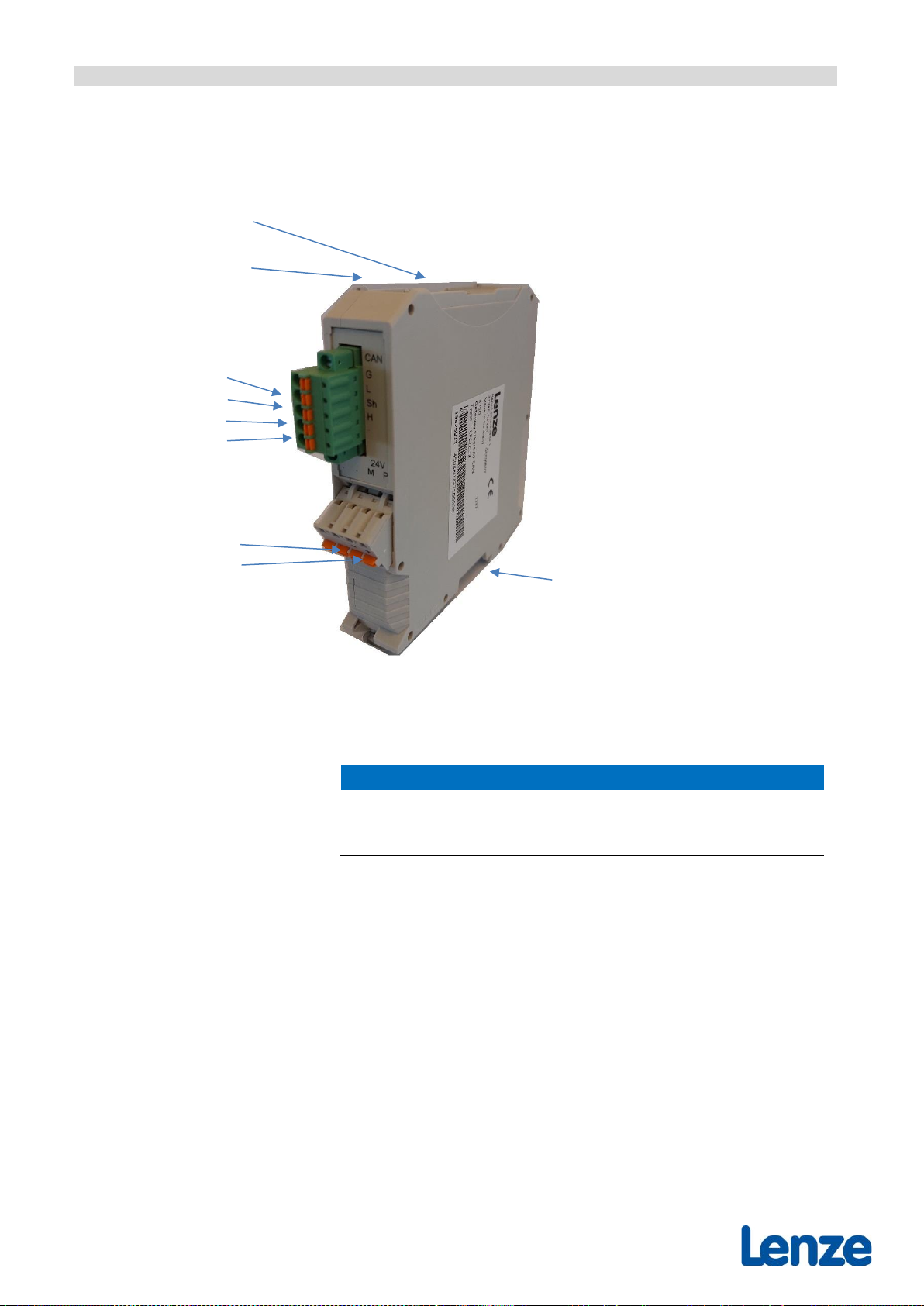
3Hardware Description...........................................................................8
3.1 Connections .........................................................................................8
3.2 LEDs.....................................................................................................9
3.2.1 LED Assignment...................................................................................9
4Hardware Installation..........................................................................11
5Configuration......................................................................................12
5.1 Application Example...........................................................................12
5.2 Configuration Sequence.....................................................................12
5.2.1 Step 1: Add Gateway .........................................................................13
5.2.2 Step 2: Add CANOpen Devices to the Project....................................13
5.2.3 Step 3: Configure the Gateway ..........................................................14
6EtherCAT Communication..................................................................16
6.1 CAN Interface.....................................................................................16
6.1.1 Object Dictionary Structure.................................................................16
6.1.2 Object Dictionary................................................................................17
6.1.3 Standard Objects (1000h...1FFFh)......................................................18
6.1.4 Manufacturer Specific Objects (2000h-5FFFh)....................................22
6.1.5 Profile Specific Objects (6000h-FFFFh)...............................................26
7Technical Data ...................................................................................37
7.1 General Technical Data......................................................................37
7.2 Microprocessor and Memory..............................................................37
7.3 CAN Interface.....................................................................................37
7.4 EtherCAT Interface.............................................................................38
7.5 Operating System and License Information........................................38
8Interfaces and Connector Assignments..............................................39
8.1 24V-Power Supply Voltage.................................................................39
8.2 CAN....................................................................................................40
8.2.1 CAN Connector ..................................................................................40
8.3 EtherCAT............................................................................................42
8.4 Conductor Connection/ Conductor Cross Sections...........................43
9Order Information...............................................................................44
10 License Terms....................................................................................45
10.1 GPL V1...............................................................................................45
10.2 GPL V2...............................................................................................46
10.3 OpenBSD License..............................................................................47
10.4 MIT Lizenz..........................................................................................47

Safety precautions
3 / 48
1 Safety precautions
This manual contains important information and instructions on safe
and efficient handling of the product. Carefully read this manual before
commencing any work and follow the instructions.
The manual is a product component, please retain it for future use.
Trademark Notices
•CANopen® and CiA® are registered EU trademarks of CAN in
Automation e.V.
•Windows is a registered trademark of Microsoft Corporation in the United
States and other countries.
•EtherCAT® is registered trademark and patented technology, licensed by
Beckhoff Automation GmbH, Germany.
•QNX® is a registered trademark of QNX Software Systems GmbH & Co.
KG
•All other trademarks, product names, company names or company logos
used in this manual are reserved by their respective owners
Document History
The changes in the document listed below affect changes in the hardware as well
as changes in the description of the facts, only.
Revision
Chapter
Changes versus previous version
Date
1.0
---
Creation
2022-11-18
Technical details are subject to change without further notice.
Classification of Warning Messages and Safety Instructions
This manual contains noticeable descriptions, warning messages and safety
instructions, which you must follow to avoid personal injuries and property
damage.
This is the safety alert symbol.
It is used to alert you to potential personal injury hazards. Obey
all safety messages and instructions that follow this symbol to
avoid possible injury or death.
DANGER, WARNING, CAUTION
Depending on the hazard level the signal words DANGER, WARNING or
CAUTION are used to highlightsafety instructions and warning messages. These
messages may also include a warning relating to property damage.
DANGER
Danger statements indicate a hazardous situation which, if not avoided, will
result in death or serious injury.

Safety precautions
4 / 48
WARNING
Warning statements indicate a hazardous situation that, if notavoided, could
result in death or serious injury.
CAUTION
Caution statements indicate a hazardous situation that, if not avoided, could
result in minor or moderate injury.
NOTICE
Notice statements are used to notify people on hazards that could result in things
other than personal injury, like property damage.
NOTICE
This NOTICE statement contains the general mandatory sign and gives
information that must be heeded and complied with for a safe use.
INFORMATION
INFORMATION
Notes to point out something important or useful.

Safety precautions
5 / 48
DANGER
Safety Instructions
•When working with the product follow the instructions below and read the
manual carefully to protect yourself from injury and the CAN-EtherCAT
from damage.
•Do not use damaged or defective cables to connect the product.
•In case of damages to the product, which might affect safety, appropriate
and immediate measures must be taken, that exclude an endangerment
of persons and domestic animals and property.
•The product may only be driven by power supply current circuits, that are
contact protected.
•A power supply, that provides a safety extra-low voltage (SELV) according
to EN 60950-1, complies with these conditions.
•Do not open the housing of the product.
•The product must be securely installed before commissioning.
•Never let liquids get inside the product. Otherwise, electric shocks or short
circuits may result.
•Protect the product from dust, moisture, and steam.
•Protect the product from shocks and vibrations.
•The product may become warm during normal use. Always allow
adequate ventilation around the product and use care when handling.
•Do not operate the product adjacent to heat sources and do not expose it
to unnecessary thermal radiation. Ensure an ambient temperature as
specified in the technical data.
DANGER
•Hazardous Voltage - Risk of electric shock due to unintentional contact
with uninsulated live parts with high voltages inside of the system into
which the EtherCAT/CAN Gateway is to be integrated.
•All current circuits which are connected to the device must be sufficiently
protected against hazardous voltage (SELV according to EN 60950-1)
before you start with the installation
Qualified Personal
This documentation is directed exclusively towards personal qualified in control
and automation engineering.
The installation and commissioning of the product may only be carried out by
qualified personal, which is authorized to put devices, systems, and electric
circuits into operation according to the applicable national standards of safety
engineering.
Conformity
The x750 Gateway EtherCAT/CAN is an industrial product and meets the
demands of the EU regulations and EMC standards printed in the conformity
declaration.

Safety precautions
6 / 48
WARNING
In a residential, commercial, or light industrial environment the product may
cause radio interference in which case the user may be required to take
adequate measures.
Data Safety
This product is equipped with an EtherCAT or other interface which is suitable to
establish a connection to data networks. Depending on the software used on the
device, these interfaces may allow attackers to compromise normal function, get
illegal access or cause damage.
Lenze does not take responsibility for any damage caused by the device if
operated at any networks. It is the responsibility of the device's user to take care
that necessary safety precautions for the device's network interface are in place.
Intended Use
The intended use of the product is the operation as EtherCAT/CAN Gateway.
The guarantee given by Lenze does not cover damages which result from
improper use, usage not in accordance with regulations or disregard of safety
instructions and warnings.
•The product is intended for indoor use.
•The operation of the product in hazardous areas, or areas exposed to
potentially explosive materials is not permitted.
•The operation of the product for medical purposes is prohibited.
Service Note
The x750 Gateway EtherCAT/CAN does not contain any parts that require
maintenance by the user. The x750 Gateway EtherCAT/CAN does not require
any manual configuration of the hardware.
Unauthorized intervention in the device voids warranty claims.
Disposal
Products which have become defective in the long run have to be disposed in an
appropriate way or must be returned to the manufacturer for proper disposal.
Please, contribute to environmental protection.
Typographical Conventions
Throughout this manual the following typographical conventions are used to
distinguish technical terms.
Convention
Example
File and path names
/dev/null or <stdio.h>
Function names
open()
Programming constants
NULL
Programming data types
uint32_t
Variable names
Count
Number Representation
All numbers in this document are base 10 (partially followed by “d”) unless
designated otherwise. Hexadecimal numbers a followed by “h”. For example, 42
is represented as 2Ahin hexadecimal.

Overview
7 / 48
2 Overview
Figure 1: Block circuit diagram
The x750 Gateway EtherCAT/CAN device connects an EtherCAT®network with
one CAN network. In this case the Gateway acts as an EtherCAT slave device
according to „Module Profile Number 5000“of the „Modular Device Profile
Description“(ETG.5001 documents).
The Gateway allows CAN modules with CANopen®(CiA®DS 301) or Layer 2
(ISO 11898-1) implementations to connect with a real-time EtherCAT network.
The Gateway does not limit the number of CAN nodes.
The high-speed CAN interface is compliant with ISO 11898-2, and it supports
transfer rates from 50 kBit/s up to 1 MBit/s. The 100BASE-TXEtherCAT interface
is IEEE802.3 compatible and runs at 100 MBit/s. The CAN interface, as well as
the EtherCAT interface, is electrically isolated.
The configuration of the Gateway is accomplished through the EtherCAT master.

Hardware Description
8 / 48
3 Hardware Description
3.1 Connections
Figure 2; Connections for operating condition
NOTICE
Read chapter “Hardware Installation” on page 11, before you start with the
installation of the hardware!
Please refer to page 39 ff. for signal assignment of the connectors.
OUT
EtherCAT
IN
EtherCAT
CAN
CAN_GND
CAN_L
Shield
CAN_H
24V
GND
+24V
Functional Earth (FE)

Hardware Description
9 / 48
3.2 LEDs
Figure 3: Connectors and LEDs
3.2.1 LED Assignment
LEDs at EtherCAT-RJ45 Connectors IN and OUT
LED
Color
LED Status
Description
Link/
Activity
green
Off
No EtherCAT link present
Blinking
EtherCAT link present,
EtherCAT activity (reception of EtherCAT data)
Spare
yellow
-
Unused
Table 1: EtherCAT LED functionality (integrated in RJ45)
Meaning of EtherCAT-LEDs U, E, R, L
LED Status
Description
Blinking
LED repeats: 200 ms on, 200 ms off.
Flicker
LED repeats: 50 ms on, 50 ms off.
single flash
LED repeats: 200 ms on, 1000 ms off.
double flash
LED repeats: 200 ms on, 200 ms off, 200 ms on, 1000 ms off.
Table 2: LED states (according to ETG.1300 documents)
U (LED yellow): Universal
E (LED red): EtherCAT ERROR indicate
R (LED green): EtherCAT RUN indicate
L (LED green): EEPROM loaded
OUT
EtherCAT OUT Port
IN
EtherCAT IN Port
EtherCAT LED (green): Link/Activity
LED (yellow): Unused
EtherCAT LED (green): Link/Activity
LED (yellow): Unused

Hardware Description
10 / 48
LED
Color
Function
LED Status
Description
U
yellow
Universal
off
No information available
blinking
Reserved
flicker
FoE firmware transfer is in progress
on
FoE firmware transfer finished. Visible only for a few seconds –then
actual firmware update is started
any
Set by CoE object 0x2000.2, see 6.1.4.1.
E
red
EtherCAT
ERROR
Indicator
off
No error
blinking
State change failed
single flash
State changed due to configuration error
double flash
SM watchdog time out
R
green
EtherCAT
RUN
Indicator*
off
Init
blinking
Pre-Operational
single flash
Safe-Operational
on
Operational
L
green
EEPROM
Loaded*
flicker
Bootstrap
off
unable to retrieve ET1100 configuration from EEPROM
on
successful retrieval of ET1100 configuration
from EEPROM
*Directly connected to the ET1100
Table 3: EtherCAT LED functionality

Hardware Installation
11 / 48
4 Hardware Installation
For proper installation and setup please follow the recommended steps as shown
here:
Step
Procedure
see
page
Read the safety instructions at the beginning of
this document carefully before you start with the
hardware installation!
3
Danger
Hazardous Voltage - Risk of electric shock due to
unintentional contact with uninsulated live parts with
high voltages inside of the system into which the
Gateway is to be integrated.
•All current circuits which are connected to the
device must be sufficiently protected against
hazardous voltage (SELV according to EN
60950-1) before you start with the installation.
•Ensure the absence of voltage before starting
any electrical work.
1.
Mount and connect the Gateway and connect the
interfaces (Power supply, CAN bus, EtherCAT).
11
2.
Please note that the CAN bus has to be terminated
at both ends!
Additionally, the CAN_GND signal has to be
connected to earth at exactly one point in the CAN
network.
Any CAN node that does not support a galvanic
isolation represents the equivalent of a Ground
(GND) connection.
3.
Turn on the 24 V-power supply voltage of the
Gateway.

Configuration
12 / 48
5 Configuration
5.1 Application Example
Figure 4: EtherCAT-CAN Gateway connection example
The Gateway can be placed anywhere in the EtherCAT network, except when
using Distributed Clocks.
NOTE
The Gateway does not support Distributed Clocks. If Distributed Clocks are
used, this must be taken into account during placement.
5.2 Configuration Sequence
The following chapter describes the CAN configuration of the Gateway by the
Lenze PLC Designer.
INFORMATION
The x750 Gateway EtherCAT/CAN works only with Controllers of the c5xx
Series and their successor.
For the Lenze Controller c3xx, c32xx, p3xx and p5xx please order the
internal CAN Options.

Configuration
13 / 48
5.2.1 Step 1: Add Gateway
Figure 5: Add x750 Gateway EtherCAT/CAN to EtherCAT Master
Add the CANOpen Manager to the Project
Figure 6: Add x750_CANOpen_Manager to the CANbus
5.2.2 Step 2: Add CANOpen Devices to the Project
INFORMATION
Supported devices:
•All devices imported directly from the CANopen device description file
(*.eds) can be used with the x750 CANopen Manager.
•The EDS files for the Lenze devices can be found at the following link:
https://www.lenze.com/en-de/go/akb/200413930/1/
•The CANopen devices 8400, 9400 (except CiA 402), i500 and Lenze
Generic Drive available in PLC Designer are supported from PLC
Designer version 3.26.
All other Lenze devices and the following Lenze device functions are not
supported:
•FAST-Motion Axis Reference
•FreeEncoder reference (LM FreeEncoder)
•FastIO reference (FastIO_InRef, FastIO_OutRef)
•Parameter set download
(Especially for EPM-S110 an integration must be done via the
EDS file)
•Gateway function for the Lenze Engineering Tools
Figure 7: Connect only Imported or supported Products to
x750_CANOpen_Manager

Configuration
14 / 48
5.2.3 Step 3: Configure the Gateway
Figure 8: Configuration of the x750 Gateway EtherCAT/CAN
Details of the Parameter:
Parameter
Description
Network
The network number of the x750 Gateway EtherCAT/CAN can be found in the variable
m_usiNetId (corresponds to the order of the gateways in the project tree, starting at 0).
Note: It should be noted that m_usiNetId must be incremented by1 if m_usiNetId
is used as parameter Network in the CAA CiA405 library.
Baudrate
CAN-Baudrate (Possible Baudrates see Chapter 6.1.5.9)
Count of Buffer
Number of Rx/Tx messages that can be processed in one EtherCAT cycle.
(Rx/Tx-queue-size; see chapter 6.1.5.5)

Configuration
15 / 48
Parameter
Description
CAN Sync Telegram
Generation in the gateway (Cycle Time >0)
The x750 Gateway EtherCAT/CAN can independently generate a
highly accurate equidistant sync telegram for the CAN bus (cyclic
telegram).
In this case the SYNC reception must be activated at the
x750_CANOpen_Manager.
Parameter x750_CANOpen_Manager
Generation in the x750_CANopen_Manager
If the SYNC telegram is to be generated in the
x750_CANopen_Manager, the setting must be activated in the
x750_CANopen_Manager and the Cycle Time in the x750
Gateway EtherCAT/CAN (see Chapter 6.1.4.2) must be set to 0.
Note: The cycle time of the Sync telegram should be selected 3 times as high
as the EtherCAT cycle time (e.g., 1ms EtherCAT cycle time, 3ms cycle
time of the SYNC telegram) to achieve an equidistant distance Parameter x750_CANOpen_Manager
between the SYNC telegrams on the CAN.
Cycle Time
see Chapter 6.1.4.2
ID
see Chapter 6.1.4.2
INFORMATION
Details of Parameter Setup of CAN Devices can be found in the Online Help
of the PLC Designer
(Engineering Tools PLC Designer Fieldbus configuration editors CAN-Based
Fieldbusses Canopen Manager (Master))
The following Topics are not supported
•CANopen Safety
•Redundancy
INFORMATION
Project planning recommendation
•Up to 10 CAN stations per Gateway with one RxPDO and TxPDO each
with 8 bytes of data per participant
(CAN cycle time depending on the used CAN baud rate).
•Cycle time EtherCAT = 1/3 * Cycle time CAN

EtherCAT Communication
16 / 48
6 EtherCAT Communication
6.1 CAN Interface
The CAN Interface is based on a modular device profile (Fieldbus Gateway,
Profile No. 5000), and it supports one CAN module. This module includes one
CAN Tx message queue in the output area and one CAN Rx message queue in
the input area.
6.1.1 Object Dictionary Structure
The object dictionary is composed of the following areas:
Index
Object Dictionary Areas
0000h ... 0FFFh
Data Type Area
1000h ... 1FFFh
Communication Area
2000h ... 5FFFh
Vendor Specific Area
6000h ... 6FFFh
Input Area (CAN Rx message queue)
7000h ... 7FFFh
Output Area (CAN Tx message queue)
8000h ... 8FFFh
Configuration Area (CAN interface configuration)
F000h ... FFFFh
Device Area
Table 4: Object dictionary structure
The following explains the definition of a standard and an extended CAN
message queue. For proper operation one of both CAN message queues must
be chosen. This can be accomplished by writing the CAN interface settings object
(8000h). The RPDO and TPDO mapping objects (1600h and 1A00h) will change
accordingly.
6.1.1.1 Output Data
The CAN interface output data include the Tx message queue plus the control
data for the Rx andTx message queues. The CAN interface outputdata is always
required.
6.1.1.2 Input Data
The CAN interface input data include the Rx message queue plus the status
information for the Rx and Tx message queues. The CAN interface input data is
always required.

EtherCAT Communication
17 / 48
6.1.2 Object Dictionary
The Gateway layer 2 implementation supports the following objects:
Index
Name
1000h
Device type
1008h
Device name
1009h
Hardware version
100Ah
Software version
1018h
Identity
1600h
RPDO-Map CAN interface
1A00h
TPDO-Map CAN interface
1C00h
Sync manager type
1C12h
RPDO assign
1C13h
TPDO assign
2000h
Other Settings
2010h
Statistics
6000h
CAN interface input (11-bit identifier)
6001h
CAN interface input (29-bit identifier)
7000h
CAN interface output (11-bit identifier)
7001h
CAN interface output (29-bit identifier)
8000h
CAN interface configuration
8001h
CAN filter table
F000h
Modular Device Profile
F108h
CAN Status
F800h
CAN bus parameter

EtherCAT Communication
18 / 48
6.1.3 Standard Objects (1000h...1FFFh)
6.1.3.1 Object 1000hDevice Type
Index
Subindex
Description
Data Type
RW
Default
1000h
0
Device Type
UINT32
RO
13881389h
Variable Description
Low Word: Used CoE profile (5001h)
High Word: Module Profile according to the modular device profile 5000h
6.1.3.2 Object 1008hDevice Name
Index
Subindex
Description
Data Type
RW
Default
1008h
0
Device Name
STRING5
RO
MEESC
Variable Description
Gateway Device Name.
6.1.3.3 Object 1009hHardware Version
Index
SubIndex
Description
Data Type
RW
Default
1009h
0
Hardware Version
STRING3
RO
1.3
Variable Description
Gateway Hardware Version.
6.1.3.4 Object 100AhSoftware Version
Index
SubIndex
Description
Data Type
RW
Default
100Ah
0
Software Version
STRING3
RO
2.6
Variable Description
Gateway Software Version.

EtherCAT Communication
19 / 48
6.1.3.5 Object 1018hIdentity
Index
SubIndex
Description
Data Type
RW
Default
1018h
0
Number of sub-indexes
UINT8
RO
4h
1
Vendor ID
UINT32
RO
3Bh(59d)
2
Product code
UINT32
RO
37500000h
3
Revision
UINT32
RO
see below
4
Serial number
UINT32
RO
see below
Variable Description
Gateway identification characteristics.
Vendor ID Lenze Vendor-ID = 3Bh(59d)
Product code Gateway product code
Revision Revision number of the Gateway
Serial number Serial number
6.1.3.6 Object 1C00hSync Manager Type
Index
SubIndex
Description
Data Type
RW
Default
1C00h
0
Number of sub-indexes
UINT8
RO
4h
1h
Sync-Manager Type Channel 1: Mailbox Write
UINT8
RO
1h
2h
Sync-Manager Type Channel 2: Mailbox Read
UINT8
RO
2h
3h
Sync-Manager Type Channel 3: Process Data Write
(Outputs)
UINT8
RO
3h
4h
Sync-Manager Type Channel 4: Process Data Read (Inputs)
UINT8
RO
4h
Variable Description
Sync-Manager Type:
Sync-Manager Type Channel 1: Mailbox Write
Sync-Manager Type Channel 2: Mailbox Read
Sync-Manager Type Channel 3: Process Data Write (Outputs)
Sync-Manager Type Channel 4: Process Data Read (Inputs)

EtherCAT Communication
20 / 48
6.1.3.7 Object 1600hRPDO-Map CAN-Interface
This object defines the CAN interface mapping into the EtherCAT input data.
The first three sub-indexes contain the size of the Tx and Rx counters plus the
number of Tx messages. The size of the CAN Rx message queue is configured
through object 8000h.
Object 8000his also used to define the CAN message ID mode, either 11-bit
(Object 7000h) or 29bit (7001h). Depending on the settings the contents of objects
7000hand 7001hare mapped in object 1600h.
Object 1600his always required and must be defined in the PDO Assign Object
1C12h, subindex 1h.
Index
SubIndex
Description
Data Type
RW
1600h
0
Number of CAN-Messages+3
UINT8
RO
1h
1. PDO Mapping entry,
(Object 700zh(CAN interface output), entry 01h(Tx Counter))
UINT32
RO
2h
2. PDO Mapping entry
(Object 700zh(CAN interface output), entry 02h(Rx Counter))
UINT32
RO
3h
3. PDO Mapping entry
(Object 700zh(CAN interface output), entry 03h
(Number of Tx Messages))
UINT32
RO
4h
4. PDO Mapping entry
(Object 700zh(CAN interface output), entry 04h(Tx Message 1))
UINT32
RO
...
..
...
...
mh
m. PDO Mapping entry
(Object 700zh(CAN interface output), entry m (Tx Message m-3))
UINT32
RO
Table of contents
Other Lenze Gateway manuals