3S SL-R60S User manual
www.3SLift.com
File No. Version Date
TD-RND-TF-065 A 2020.8
EN
SL-R60S Fall Arrester
Operation And Maintenance Manual
Ficont Industry (Beijing) Co., Ltd.
1005, SK Tower, No.6 Jia, Jianguomenwai Avenue, Beijing, China
No. 15, Chuangyi East 2nd Road, Xiji Development Zone, Tongzhou, Beijing, China
Tel: +86 10 69597866
E-mail: [email protected]
Ficont Industry (Tianjin) Co., Ltd.
No. 8, Cuiyuan Road, Wuqing Development Zone, Tianjin, China
Tel: +86 022 22140477
E-mail: [email protected]
3S Americas, Inc.
2840 Guilder Drive, Suite 100, Plano Texas, 75074 USA
Tel: +1 312 6232662
E-mail: [email protected]om
3S Europe GmbH
Erdmannstr. 10, 22765 Hamburg, Germany
E-mail: [email protected]
3S Lift India Private Limited
No. 2C Shyams Garden, Khadar Nawaz Khan Road,
Nungambakkam, Chennai – 600006, India
E-mail: [email protected]

Limited Warranty ................................................................................. 1
1. Precautions .......................................................................................2
2. Product Description & Components ............................................5
3. Specifications...................................................................................6
4. Marking..............................................................................................7
5. Operation ..........................................................................................9
6. Inspection ........................................................................................ 11
7. Storage ............................................................................................ 13
8. Repair and Maintenance .............................................................. 13
Appendix 1:Routine Inspection..................................................... 14
Appendix 2:Annual Inspection ..................................................... 15
Contents

1 2
SL-R60S Fall Arrester
Limited Warranty
3S Lift warrants that commencing from the date of shipment to the Customer and
continuing for a period of the longer of 365 days thereafter, or the period set forth in the
standard 3S Lift warranty, the Product described in this Manual will be free from defects
in material and workmanship under normal use and service when installed and operated in
accordance with the provisions of this Manual.
This warranty is made only to the original user of the Product. The sole and exclusive remedy
and the entire liability of 3S Lift under this limited warranty, shall be, at the option of 3S Lift, a
replacement of the Product (including incidental and freight charges paid by the Customer)
with a similar new or reconditioned Product of equivalent value, or a refund of the purchase
price if the Product is returned to 3S Lift, freight and insurance prepaid. The obligations of
3S Lift are expressly conditioned upon return of the Product in strict accordance with the
return procedures of 3S Lift.(i) has been altered without the authorization of 3S Lift or its
authorized representative;
This warranty does not apply if the product:
(ii) has not been installed, operated, repaired, or maintained in accordance with this
Manual or other instructions from 3S Lift;
(iii) has been subjected to abuse, neglect, casualty, or negligence;
(iv) has been furnished by 3S Lift to Customer without charge; or
(v) has been sold on an “AS-IS” basis.
Except as specifically set forth in this Limited Warranty,All express or implied conditions,
representations and warranties, including, but not limited to, any implied warranty or
condition of merchantability, fitness for a particular purpose, non-infringement, satisfactory
quality, course of dealing, law, usage or trade practice are hereby excluded to the maximum
extent permitted by applicable law and are expressly disclaimed by 3s lift. If, pursuant to
any applicable law, to the extent an implied warranty cannot be excluded as provided in this
limited warranty, any implied warranty is limited in time to the same duration as the express
warranty period set forth above. Because some states do not permit limitations on the duration
of implied warranties, this may not apply to a given customer. This limited warranty gives
customer specific legal rights, and customer may have other legal rights under applicable laws.
This disclaimer shall apply even if the express warranty fails of its essential purpose.
In any cases of dispute, the Chinese original shall be taken as authoritative.

3 4
SL-R60S Fall Arrester
Precautions
withstand the loads specified in the
standards.
1.3 The operator must have obtained a
proper professional training, be familiar
with the operation and installation of
product, and have the ability to attach,
detach and use the product. The
operator must always wear personal
protective equipment, such as safety
helmet, safety shoes and safety gloves,
etc.
1.4 Maximum of 2 operators are allowed on
the same ladder and to attach to the fall
protection system at a time, in which
case a minimum distance of 6 m must
be maintained between them.
1.5 The operator may not be protected
against hitting the ground or the starting
platform within the first 2 m climbing.
Therefore, particular caution must be
taken when operator starts climbing.
The Manual is supplied in the language of
the designated country where the product
is used. The translations in various languages
must be authorized by 3S Lift. The operator
must read, understand and follow these
complete product instructions. Failure to do
so may cause severe injury or death. Keep the
product instructions for future references.
1.1 The fall arrester is an integral component
of fall protection system which falls
into category of personal protection
equipment (PPE). Both the fall arrester
and fall protection system we offer
conform to EN353-1:2014+A1: 2017, ANSI/
ASSE Z359.16-2016 and CSA Z259.2.4. The
fall arrester shall be used in conjunction
with a full body harness that is fitted
with a sternal attachment point in
accordance with EN361 and ANSI Z359.11.
1.2 The ladder on which the fall protection
system is mounted should conform
to EN131-2, EN 14122-4, ANSI A14.3 and
1.6 When attaching or detaching the fall
arrester to/from fall protection lifeline,
ensure that the operator is at a safe
position and protected by a separate
personal protection equipment.
1.7 To achieve the optimal operation and
improve safety, keep a minimum
distance of 100mm between torso and
ladder during normal climbing, and
keep correct climbing postures.
1.8 The weight of the operator (including
tools and equipment) shall not exceed
the rated load of 140 kg (310 lbs).
1.9 The weight of the operator (excluding
tools and equipment) shall not be less
than 30 kg (66 lbs).
1.10 The fall arrester shall never be used
for work positioning or for securing
equipment. If work positioning at the
ladder is required, a separate dedicated
and approved work positioning
equipment shall be used.
1.11 A fall arrester can only be used by one
operator at a time.
1.12 Service temperature of fall arrester is
-40°C to +60°C. Ensure that the system is
free of grease oil and ice.
1.13 According to OSHA 1926.1053, the
connection between the fall arrester and
the attachment point of the full body
harness shall not exceed 23 cm (9 inches)
in length! The length of the connection
shall not be extended or shortened, e.g.
by adding or subtracting a connector.
1.14 Always wear a full body harness that
perfectly fits. If it becomes loose during
ascent or descent, adjust it to a snug fit
in time at a safe position.
1.15 The operator must be in good health
without acrophobia, hypertension,
or heart disease, and not be under
influence of alcohol or drugs during
operation.
1.16 If the equipment is found abnormal
during operation, the operator must
immediately stop using it and notify the
equipment administrator.
5 6
SL-R60S Fall Arrester
1.17 No modification or extension of the
fall protection system shall be allowed
without prior written consent of 3S
Lift. Otherwise for any consequences
affecting the product performance
and safety, 3S Lift will not assume any
liabilities.
1.18 DO NOT carry tools or materials by hands
while climbing up or down the ladder,
during which a fall of tools or materials
may occur resulting in damage to
equipment or injury to personnel below.
1.19 Before each use, perform a routine
inspection to ensure that the fall
arrester functions properly. The annual
inspection shall be performed by a
competent person
1.20 A copy of the user’s manual must be
handed out to the operator and must be
available for reference.
1.21 Before and during use of the fall
protection system, a rescue plan
which copes with all kinds of possible
emergencies should be in place.
1.22 The fall arrester can only be used in
conjunction with 3S Lift rail guided fall
protection system, or a written consent
by 3S Lift shall be obtained if it is
intended to be used with other systems
other than described herein. Otherwise,
for any consequences affecting the
product performance and safety, 3S Lift
will not assume any liabilities.
1.23 The installation, maintenance and
inspection of the fall protection system
can only be performed by qualified
personnel trained by 3S Lift, or under the
guidance of related professionals.
1.24 Follow site emergency protocol. Do not
use the fall arrester as an assisted rescue
device.
1.25 DO NOT use the fall protection system in
environments where the user is exposed
to hazards such as high heat, chemicals
or falling risks that could result in injury
to the user.
1.26 Long distance climbing may require
several movable rest standings mounted
in the climbing passage to avoid fatigue.
Use proper work positioning equipment
for rest breaks. Do not climb in strong
winds or adverse weather.
1.27 Always maintain three points of contact
(hands and feet) with the ladder while
climbing. Should a mis-locking of the fall
arrester occur, the operator shall climb
up a bit to unlock the fall arrester.
Note: Should the fall arrester lock on the
guide rail, never unlock it by means of
detaching it off the guide rail.
1.28 If the fall arrester has been subjected to
a fall which leads to deformation, it must
be removed out of service immediately
and scrapped.
1.29 The ladder onto which the fall
protection system is mounted can be
installed on the tower wall in accordance
with the information supplied by the
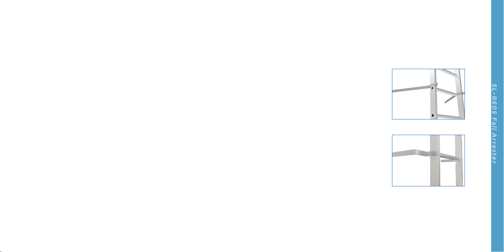
manufacturers (see Fig. 1.1 and Fig. 1.2).
For example: weld a base plate with
embeded bolt onto the wall of wind
turbine tower, mount a supporting
bracket onto base plate, and fix the
supporting bracket to the ladder stile
with a clamp. The ladde should have a
capacity of supporting static load of 16
kN (3600 lbs).
Fig. 1.1
Fig. 1.2
7 8
SL-R60S Fall Arrester
Product Description & Components
Fall arrester (SL-R60S) is used on the rigid guide rail lifeline. When using the fall arrester,
connect the carabiner of fall arrester onto the sternal attachment point of operator's full body
harness. When a fall occurs, the fall arrester will lock on the guide rail automatically.
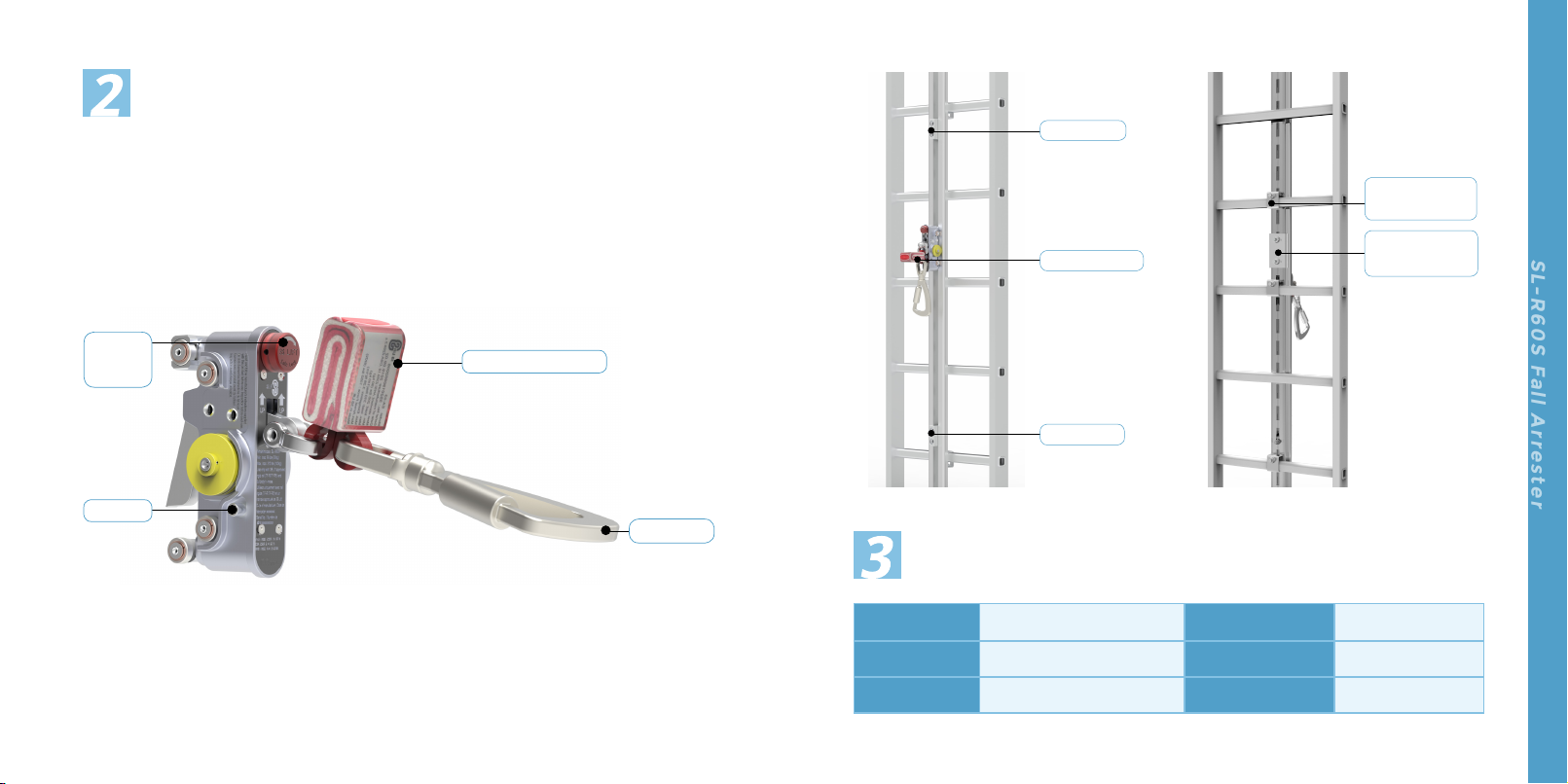
2.1 The fall arrester is shown in Fig. 2.1 .
2.2 Rigid guide rail lifeline is shown in Fig. 2.2 and Fig. 2.3.
Fig. 2.1
Rotary
knob
Button
Carabiner
Shock absorber
Fig. 2.2 Fig. 2.3
Clamp and
fasteners
Rail fishplate
and fasteners
Specications
End stop
End stop
Fall arrester
Model SL-R60S Self Weight 1.75 kg (3.9 lbs)
Static strength 16 kN (3600 lbs) Rated Load 140 kg (310 lbs)
Dimensions 280 mm× 160 mm× 61 mm Guide Rail Model TF-R/ TF-R5
9 10
SL-R60S Fall Arrester
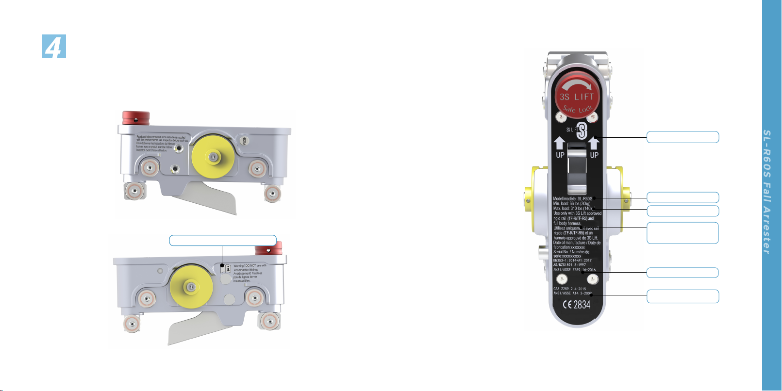
Marking
The markings shall be legible and clear. During maintenance, check the engraved markings. If
they are not clearly legible, return the fall arrester to 3S Lift for repair. The marking details are
shown in the following figures (See Fig.4.1, Fig.4.2 and Fig.4.3)
FIg. 4.1
Fig. 4.2
Read instructions before use
Fig. 4.3
Attaching direction
Model
Compatible guide
rail model
Load capacity
Serial No.
Reference standard
11 12
SL-R60S Fall Arrester
Attention!
Ensure that the safety
carabiner is fully closed and
locked.
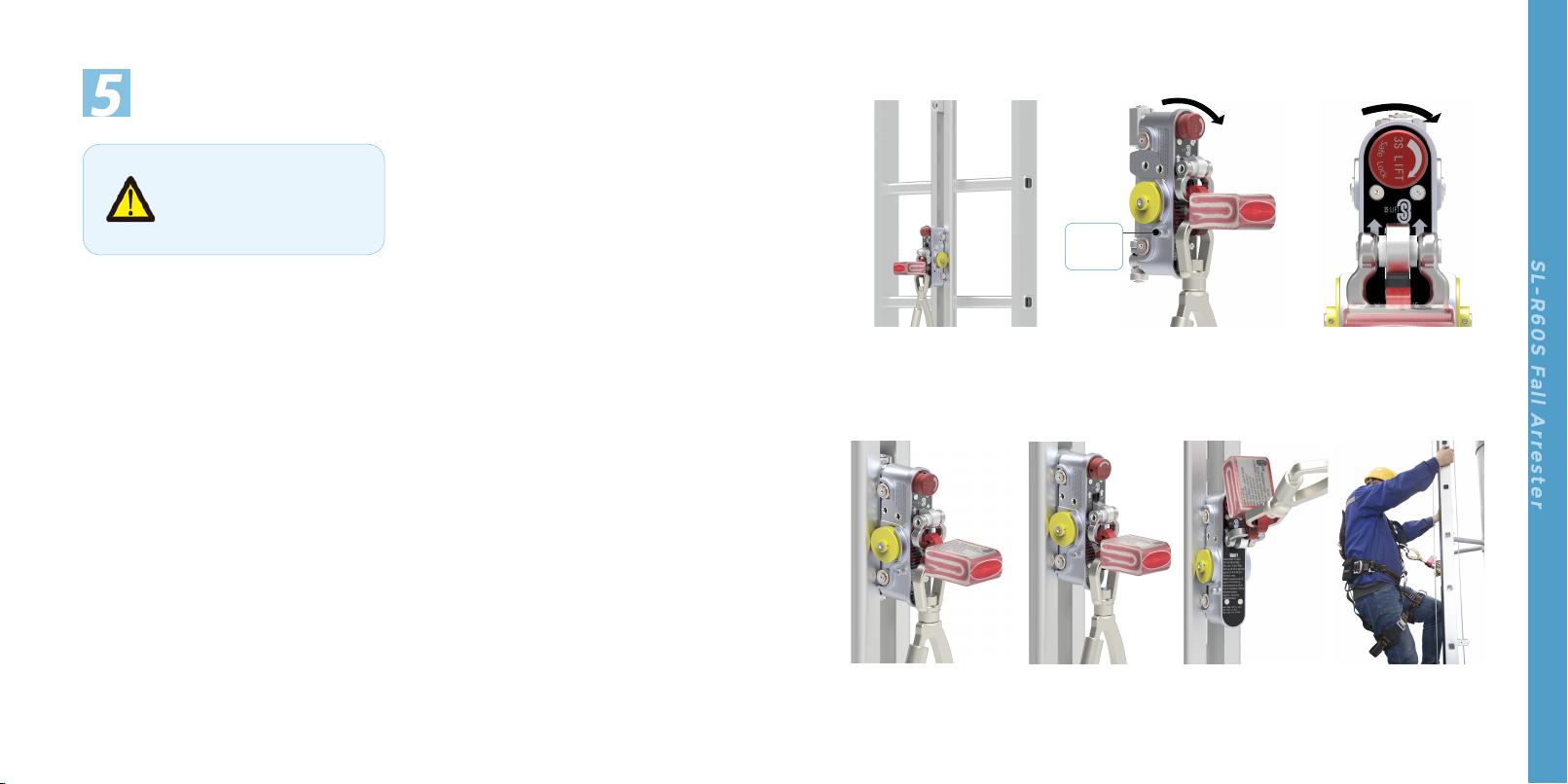
Operation
5.1 Attach the fall arrester to the guide rail at
any position. The guide rail should have
been installed along the central line of
the ladder. (As in Fig. 5.1)
5.2 Press down the button and turn the
rotary knob clockwise to its limit, hold
the button and knob, and put the rollers
into the slot of the guide rail. (See Fig. 5.2,
Fig. 5.3 and Fig. 5.4.)
5.3 Release the button and the rotary knob
to let them return to their original
positions. (See Fig. 5.5)
5.4 The fall arrester is ready for use. (See Fig.
5.6)
5.5 Connect the carabiner to the sternal
attachment point of the full body
harness, and ensure the gate of the
carabiner is closed and locked. The fall
protection system is well established for
fall protection at the time.(See Fig. 5.7)
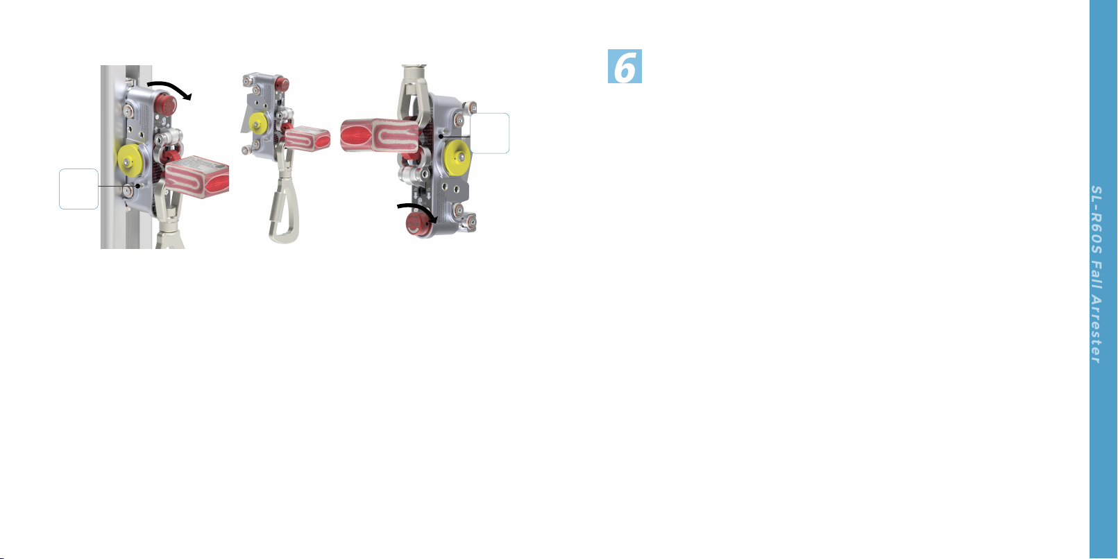
5.6 To detach the fall arrester, press down
the button and turn the rotary know
clockwise, hold the button and knob, and
detach the fall arrester off the rail. (See
Fig. 5.8)
5.7 Release the button and rotary knob to let
them return to their original positions. (As
in Fig. 5.9)
5.8 Open the the gate of the carabiner to
disconnect it from the full body harness
of the operator.
5.9 The fall arrester is integrated with anti-
reverse mechanism, which disenables
the user to turn the rotary knob if he
attempts to attach the fall arrester
upside-down, therefore making reverse
attaching impossible. (See Fig. 5.10)
Fig. 5.1 Fig. 5.2 Fig. 5.3
90°
90°
Press
down
Fig. 5.5 Fig. 5.6 Fig. 5.7
Fig. 5.4
13 14
SL-R60S Fall Arrester
Fig. 5.8 Fig. 5.9 FIg. 5.10
90°
Press
down 90°
Press
down
Inspection
The fall protection system shall be inspected
at least once a year by a certified technician,
and can be used only if the inspection reveals
no problem. If a fall occurs, inspection and
maintenance of the fall protection system
including fall arrester, guide rail and ladder,
etc. must be performed by competent
personnel other than the operator.
Note: Use a separate fall protection system
while inspecting and maintaining the
fall protection system.
If any fault or defect of the fall protection
system is found during routine inspection or
annual inspection, the fall protection system
shall not be used until troubleshooting
is conducted. The fault or defect shall be
reported to the equipment administrator,
and the system including the fall arrester
shall be inspected by competent personnel
who should record the fault or defect and
decide on repair or scrapping. Before each
use, conduct routine inspection of the system
in accordance with Section 6.1 and Section
6.2.
6.1 Visual check
6.1.1 Check the guide rail: During upward
climbing, visually check the guide
rail and its joints for any damage or
deformation. Ensure that all fasteners
are secured well, and guide rail
sections have been correctly installed
in accordance with instructions.
6.1.2 Check the fall arrester: check the
locking lever and swing lever for any
damage or deformation. Ensure that
the shock absorber is complete and has
not extended, and that the carabiner is
complete without break or crack.
6.2 Function check
6.2.1 Check whether the fall arrester
functions normally by following the
instructions below. Stop using if any
damage or defect is found.
6.2.2
Press down the button on fall arrester
and turn the rotary knob clockwise (to
its limit) simultaneously, hold and then
15 16
SL-R60S Fall Arrester
release both the button and
rotary knob and see whether they
automatically return to their original
positions.
6.2.2
Press down the button on fall arrester
and turn the rotary knob clockwise
(to its limit) simultaneously, hold and
then release both the button and
rotary knob and see whether they
automatically return to their original
positions.
6.2.3 Pull the fall arrester up and down the
rail, then release it and see whether it
locks on the guide rail immediately.
6.3 Annual Inspection
6.3.1 Perform the visual check and function
check following clause 6.1 and clause
6.2 during annual inspection.
6.3.2 Ensure that the locking lever and swing
lever rotate without clamp stagnation
when the carabiner of fall arrester is
pulled up, and automatically return
to their original positions when the
carabiner is released.
6.3.3 Ensure that the fall arrester is free of oil,
grease, dust and the like. Clean the fall
arrester if necessary with steel wire or
brush in such manner as not to cause
component damage. If the fall arrester
does not function normally due to oil
or dirt, return it to 3S lift for repair.
6.3.4 Ensure that all shafts and other
components are secured well and all
rollers rotate freely.
6.3.5 If any malfunction or defect is found
before or during inspection, the fall
arrester shall not be used further
and shall be returned to 3S Lift for
repair. An annual inspection of the fall
protection system shall be performed
by competent personnel, during which
any abnormality should be recorded
and maintained.
6.3.6 Inspect the connection between the
ladder and the fall protection system
to verify that the ladder equipped
with fall protection system is in good
working condition. In case of damage,
deformation or other defects, notify the
relevant person.
Note:Parts which are not provided or
approved in written by 3S Lift shall not
be used.
6.3.7 Ensure that the guide rail is in good
condition without deformation,
cracks or other defects, and its joints
(between its sections) are aligned with
a clearance less than 2 mm.
6.3.8 Check all labels of the fall protection
system for damage or loss, and replace
with or affix new labels as needed.
6.3.9 Ensure that all end stops, fish plates
and fasteners of the fall protection
system are secured well.
6.3.10 Ensure that the metal parts of fall
arrester show no signs of corrosion and
oxidation. If any, consult competent
personnel of 3S lift who will determine
between replacement or scraping.
6.4 Criteria of disposing the fall
arrester
6.4.1 The fall arrester is designed with
service life of 5 years. However, the
actual service life is dependent on use
Fig.6.1 Fig.6.2
environment, temperature, storage and
frequency of use. Extreme temperature,
fall, or contamination by harmful
substances will adversely affect the
service life.
6.4.2 If the routine inspection or annual
inspection reveals that the fall arrester
fails to meet prescribed criteria and
cannot be repaired, the fall arrester
shall be scrapped.
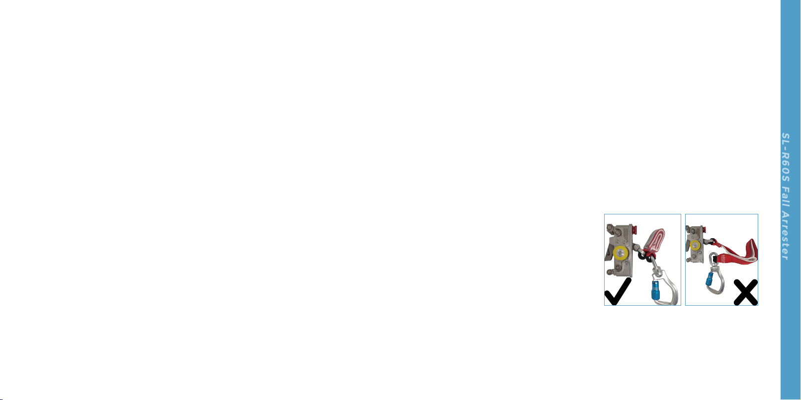
6.4.3
A fall arrester which has blocked a fall
shall not be used any more.(As in Fig. 6.1
and Fig. 6.2)

17 18
SL-R60S Fall Arrester
Repair and maintenance
8.1 When the guide rails and the fall arrester
are found to be contaminated by
corrosive substances such as oil, grease,
paint or other substances during the
inspection following clause,8, please
clean them with warm water and a little
soft detergent. Do not use other cleaning
agents.
8.2 Wipe it off with a clean cloth and then
dry them in air. Do not dry with an
artificial heat source.
8.3 If necessary, a small amount of oil can be
added at the contacts between the rollers
and the shafts, to ensure that the rollers
smoothly rotate without abnormal noise.
8.4 Repair and maintenance must be carried
out by a qualified person who must be
familiar with and fully understand the
instructions.
7.1 Personal protective equipment should be
stored in a cool, dry, clean environment,
and out of direct sunlight.
7.2 Do not expose the fall arrester and full
body harness to the corrosive substances
including oil, grease, paint or other
chemicals. Otherwise the service life of
the product might be shortened.
7.3 The reconstruction or modification of
fall arrester is not allowed. 3S Lift will not
assume any responsibility of any injury
or death caused by reconstruction or
modification of the fall arrester.
7.4 The fall arrester and full body harness
should be stored and carried in tool kit or
packing box.
Storage Routine Inspection
Inspection record
Date of inspection: Model/Standard:
Inspected by: Serial number:
Date of initial use:
Inspection items Remarks
Yes No
1. Check and ensure no damage, oil, dust, or dirt on the surface of the fall
arrester.
2. Check and ensure no deformation or fracture of the carabiner. Check
and ensure that the gate of the carabiner can be closed and locked
automatically.
3. Check and ensure all rollers rotate flexibly.
4. Check and ensure no deformation and damage on the fall arrester, and
that the locking lever and swing lever rotate flexibly without clamping
stagnation when the carabiner is lifted, and return to original position
automatically after the carabiner is released.
5. Check and ensure that the push button and rotary knob return to their
original positions after they are released.
6. Check and ensure the shock absorber is intact without being extended.
7. Check and ensure all fasteners are firmly riveted and no obvious tear or
deformation.
This table can only be filled in by competent person, and can be duplicated for further use.
Appendix

19 20
SL-R60S Fall Arrester
Inspection record
Date of annual inspection: Model/Standard:
Inspected by: Serial number:
Date of initial use:
Inspection requirements Remarks
Yes No
1. Check and ensure no damage, oil, dust, or dirt on the surface of the fall
arrester.
2. Check and ensure no deformation or fracture of the carabiner. Check
and ensure the gate lock of carabiner can be automatically closed.
3. Check and ensure all rollers rotate flexibly.
4. Check and ensure no deformation and damage on the fall arrester, and
that the locking lever and swing lever rotate flexibly without clamping
stagnation when the carabiner is lifted, and return to original position
automatically after the carabiner is released.
5. Check and ensure that the push button and rotary knob return to their
original positions after they are released.
6. Check and ensure the shock absorber is intact without being extended.
7. Check and ensure the joint gap is less than 2mm.
8. Check and ensure that when the fall arrester moves along the guide rail,
no abnormal noise is heard.
9. Check and ensure all connections by riveting are secure without obvious
wear, deformation or dislocation of torque marks.
Annual Inspection
Appendix
Inspection requirements Remarks
Yes No
10.Ensure no deformation, cracks or looseness on the ladder and guide
rail.
11. Ensure that the end stops on the rail type fall protection system are
mounted properly.
12. Ensure that all mounting brackets and fasteners are well secured.
13. Ensure completeness and legibility of the markings on the fall arrester.
This table can only be filled in by competent person, and can be duplicated for further use.
Table of contents
Popular Safety Equipment manuals by other brands

Lanex
Lanex PB-20 instruction manual

SKYLOTEC
SKYLOTEC ANCHOR ROPES Instructions for use

Besto
Besto Buoyancy Aid 50N Instructions for use

TEUFELBERGER
TEUFELBERGER NODUS Manufacturer's information and instructions for use

Troy Lee Designs
Troy Lee Designs Tbone Product owners manual

Innova
Innova Xtirpa Instruction and safety manual

bolle SAFETY
bolle SAFETY B810 quick start guide

SHENZHEN FANHAI SANJIANG ELECTRONICS
SHENZHEN FANHAI SANJIANG ELECTRONICS A9060T instruction manual

Hiltron security
Hiltron security POWER8E Installation and use manual

Salewa
Salewa MTN SPIKE user manual

Hatco
Hatco B-950P installation guide

Sitec
Sitec TX MATIC operating manual


