AMC 1022M Series User manual

IMPORTANT:
PLEASE READ THESE INSTRUCTIONS
CAREFULLY BEFORE BEGINNING
INSTALLATION AND/OR OPERATION OF
THIS EQUIPMENT.
Revised 01/27/2000
Filename: Manual_amc 1022M Copyright © September 1989
The Armstrong Monitoring Corporation
(613) 225-9531 —
(613) 225-6965 — Fax
(800) 465-5777 — U.S. Toll Free
www.armstrongmonitoring.com
1022M
AMC-1022M SERIES
HAZARDOUS GAS MONITORING
SYSTEM INSTRUCTION MANUAL


AMC
AMCAMC
AMC-
--
-1022M
1022M1022M
1022M
iii
TABLE OF CONTENTS
Page
TABLE OF CONTENTS...................................................................................................III
WARRANTY ................................................................................................................... IV
LIABILITY................................................................................................................................................................IV
MODIFICATIONS AND SUBSTITUTIONS........................................................................................................IV
PRODUCT RETURN UNDER WARRANTY ......................................................................................................IV
SPECIFICATIONS............................................................................................................ V
1 INTRODUCTION........................................................................................................ 1
1.1 GENERAL DESCRIPTION......................................................................................................................... 1
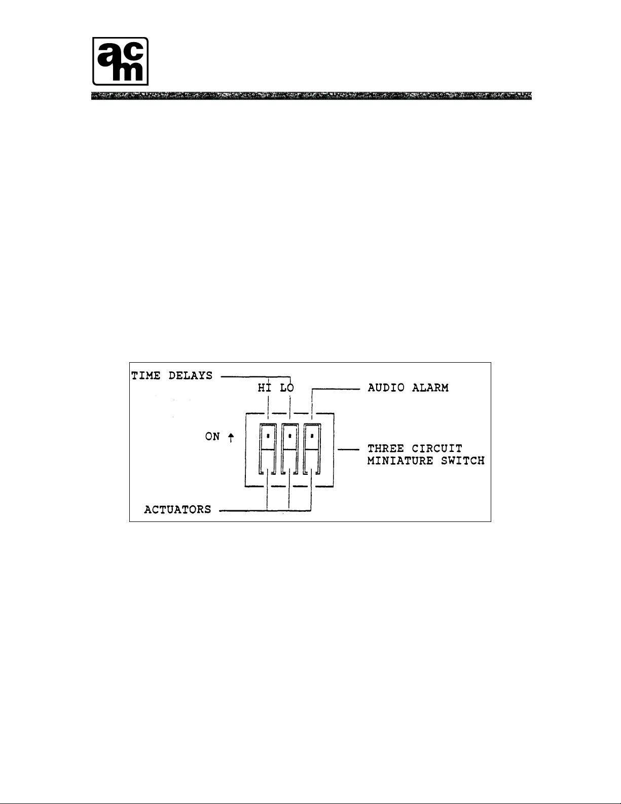
Figure 1.1 Three circuit miniature switch........................................................................................... 2
Figure 1.2 AMC-1022M series monitor, front panel......................................................................... 3
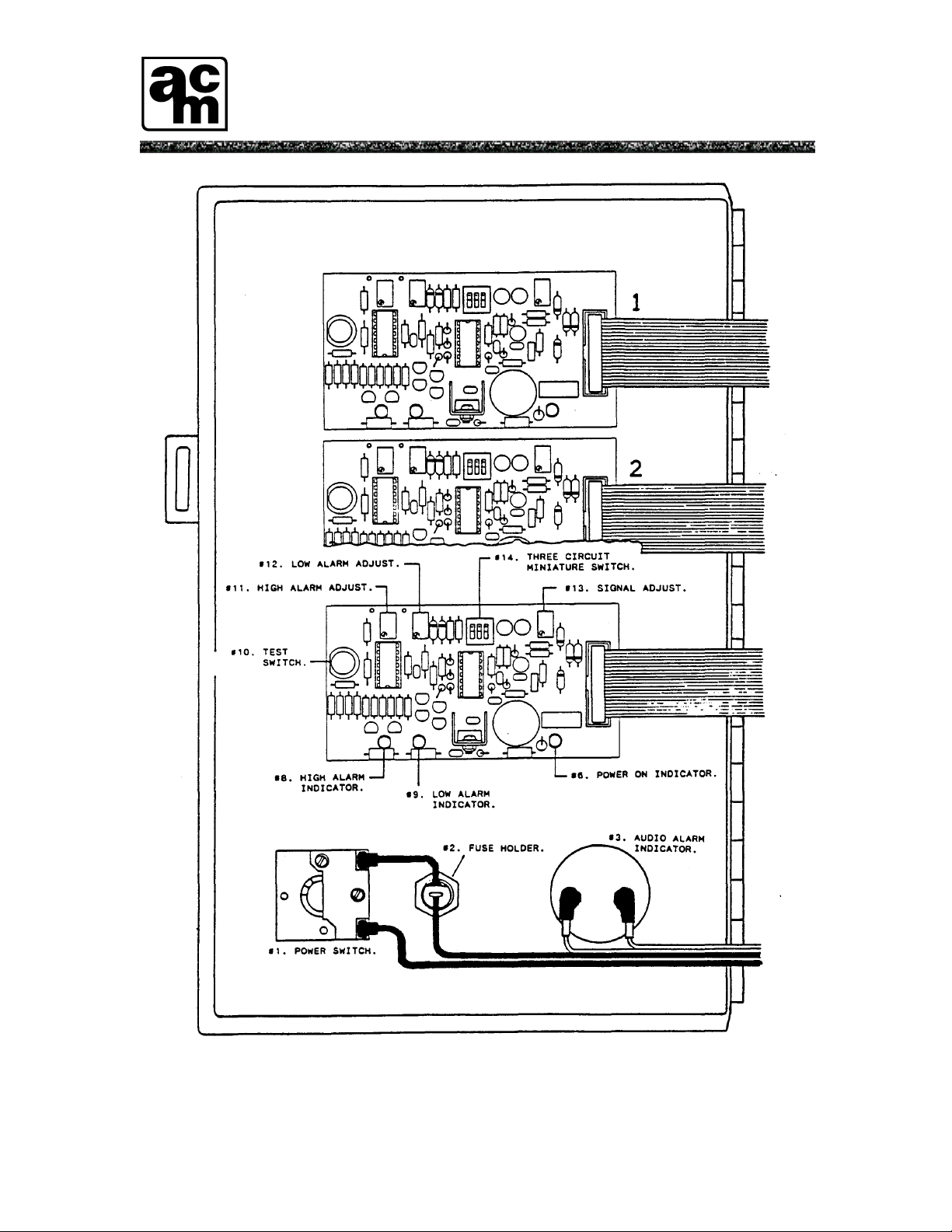
Figure 1.3 AMC-1022M series monitor, inside front panel. ............................................................. 4
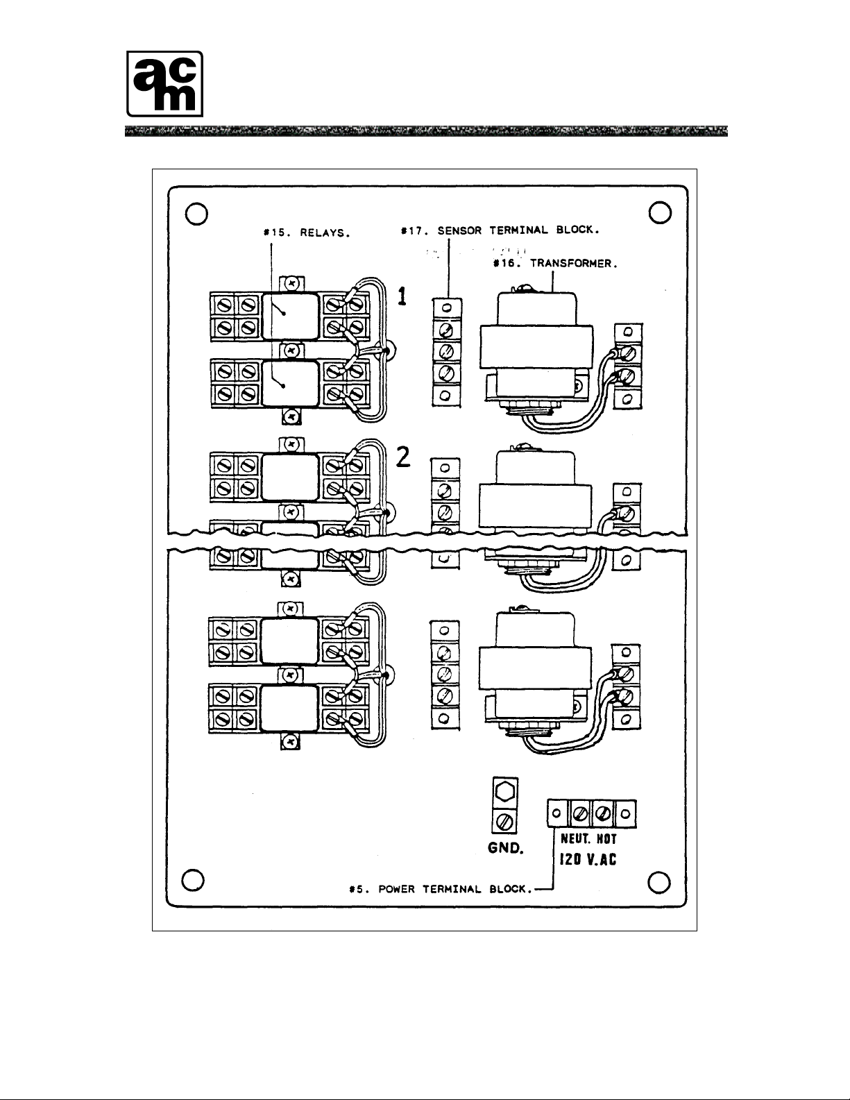
Figure 1.4 AMC-1022M series monitor, inside power/relay panel. .................................................. 5
2 INSTALLATION......................................................................................................... 6
2.1 LOCATION AND MOUNTING................................................................................................................. 6
2.2 WIRING OF THE MONITOR & SENSORS AND/OR TRANSMITTERS........................................... 6
Figure 2.1 Monitor power supply connections. ................................................................................ 7
2.3 SCHEDULE OF CABLE SIZES ................................................................................................................. 7
Figure 2.2 Monitor mounting dimensions. ........................................................................................8
Figure 2.3 remote sensor/transmitter wiring layout (one channel) .................................................... 9
Figure 2.4 Relay contact arrangement ............................................................................................. 10
3 OPERATION AND CALIBRATION ....................................................................... 11
3.1 OPERATION............................................................................................................................................... 11
3.2 CALIBRATION.......................................................................................................................................... 11
3.2.1 APPLYING CALIBRATION GAS SAMPLE(S) ................................................................ 11
3.2.2 ADJUSTMENTS.................................................................................................................. 11
Figure 3.1 Trimmer adjustments and test point locations................................................................. 13
4 MAINTENANCE....................................................................................................... 14
4.1 GENERAL................................................................................................................................................... 14
4.2 VERIFICATION OF OPERATION.......................................................................................................... 14
4.3 SENSOR REPLACEMENT....................................................................................................................... 14

AMC
AMCAMC
AMC-
--
-1022M
1022M1022M
1022M
iv
WARRANTY
The AMC-1022M series monitor is warranteed against defects in material and workmanship for a period of
two years from date of delivery. During the warranty period, we will repair or replace components that
prove to be defective in the opinion of the Armstrong Monitoring Corporation. We are not liable for
auxiliary interfaced equipment, nor consequential damage.
NOTE
ANY SUBSTITUTION OR TAMPERING WITH COMPONENTS WITHOUT THE EXPRESS
PERMISSION OF THE ARMSTRONG MONITORING CORPORATION MAY RESULT IN
DAMAGE THAT MAY CANCEL THE EFFECTIVENESS OF THE WARRANTY.
LIABILITY
All Armstrong Monitoring Systems must be installed and maintained according to instructions. Only
qualified technicians should install and maintain the equipment.
The Armstrong Monitoring Corporation shall not be responsible for any liability arising from auxiliary
interfaced equipment, consequential damage, or the installation and operation of this equipment.
Armstrong’s total liability is contained in the warranty conditions stipulated above. No other acceptance of
liability is expressed or implied by the Armstrong Monitoring Corporation.
Read this manual carefully, as the purchaser is entirely responsible for installation and operation.
MODIFICATIONS AND SUBSTITUTIONS
Due to an ongoing development program, Armstrong reserves the right to modify the design and substitute
components in any of its products without prior notice. All changes are at the sole discretion of Armstrong,
and Armstrong shall not be liable for any costs arising out of such modifications or substitutions, which
may be incurred by the user.
PRODUCT RETURN UNDER WARRANTY
All products that must be returned for warranty service will be by prepaid freight and they will only be
accepted with an R.M.A. number issued by The ARMSTRONG MONITORING CORPORATION. Goods
returned to the client will be freight collect.

AMC
AMCAMC
AMC-
--
-1022M
1022M1022M
1022M
v
SPECIFICATIONS
Monitor Serial Number........................................................................................................_______________
Power Supply Requirement ....................................................................................................120 VAC, 60 Hz
Fuse Type and Rating.............................................................................................................. 3AG, ___ Amp
Operating Temperature Range...................................................................................................... 0°C to 40°C
Sensors/Transmitters Alarm Trip Points
Chan.
No. Part No. Serial No.
Type of Gas
Low High
1
2
3
4
5
6
7
8
9
10
11
12
NOTE
ALL ARMSTRONG MONITORING SYSTEMS MUST BE INSTALLED AND MAINTAINED
ACCORDING TO INSTRUCTIONS, TO ASSURE PROPER OPERATION. ONLY QUALIFIED
TECHNICIANS SHOULD INSTALL AND MAINTAIN THE EQUIPMENT.

AMC
AMCAMC
AMC-
--
-1022M
1022M1022M
1022M
1
1 INTRODUCTION
1.1 GENERAL DESCRIPTION
NOTE
ITEMS 6 THROUGH 17 DESCRIBE FEATURES OF ONE CHANNEL ONLY. THESE
FEATURES ARE NORMALLY IDENTICAL FOR ALL CHANNELS.
The AMC-1022M is a multi-sensor gas monitoring system designed to continuously monitor for traces of
hazardous gases (listed in Specifications, page v). It can be calibrated to detect a wide variety of gases, and
each channel can monitor a different gas. The monitor comes with the following features as shown in
Figures 1-2, 1-3 and 1-4:
1. POWER SWITCH -Main AC power switch for all channels.
2. FUSE HOLDER -Front panel mounted for easy access to the fuse.
3. AUDIO ALARM INDICATOR -When operational (see item 14), the buzzer will
activate when a high alarm condition occurs.
4. CLAMPS -To secure the front panel, restricting access to internal
controls.
5. POWER TERMINAL BLOCK -For line voltage connections (120 VAC, 60 Hz.).
6. POWER ON INDICATOR -Power is indicated by a green LED.
7. FAIL INDICATOR -Sensor/transmitter signal fail is indicated by an amber
LED. (Only when this option is installed).
8. HIGH ALARM INDICATOR -High levels of gas is indicated by a red LED.
9. LOW ALARM INDICATOR -Low levels of gas is indicated by a yellow LED.
10. TEST SWITCH -The test switch is provided to electronically simulate
alarms in order to test the low and high alarm
indicators, relays, and the audio alarm indicator.
11. HIGH ALARM ADJUST -Sets the High alarm trip point.
12. LOW ALARM ADJUST -Sets the Low alarm trip point.
13. SIGNAL ADJUST -Sets the sensitivity of the sensor. (Not required for
transmitter).

AMC
AMCAMC
AMC-
--
-1022M
1022M1022M
1022M
2
14. THREE CIRCUIT MINIATURE SWITCH -Each actuator on the miniature switch controls a
different circuit as shown in Figure 1-1. If the actuator
is set in the UP position, its corresponding circuit is
ON. If the actuator is set in the DOWN position, the
circuit is OFF.
LEFT ACTUATOR: Provides a TEN minute time delay, when switch is ON, to eliminate
unnecessary alarms caused by momentary exposure to high levels of
gas.
MIDDLE ACTUATOR: Provides a FIVE minute time delay, when switch is ON, to eliminate
unnecessary alarms caused by momentary exposure to low levels of
gas.
RIGHT ACTUATOR: Controls the audio alarm indicator. When ON, the buzzer will activate
when a high alarm condition occurs.
FIGURE 1.1 THREE CIRCUIT MINIATURE SWITCH
15. RELAYS -There are two DPDT relays per channel which work
with high alarm and low alarm respectively.
16. TRANSFORMER -Class II, step down transformers run the internal
circuitry at low voltages.
17. SENSOR TERMINAL BLOCK -For remote sensor or transmitter connections.

AMC
AMCAMC
AMC-
--
-1022M
1022M1022M
1022M
3
FIGURE 1.2 AMC-1022M SERIES MONITOR, FRONT PANEL.

AMC
AMCAMC
AMC-
--
-1022M
1022M1022M
1022M
4
FIGURE 1.3 AMC-1022M SERIES MONITOR, INSIDE FRONT PANEL.

AMC
AMCAMC
AMC-
--
-1022M
1022M1022M
1022M
5
FIGURE 1.4 AMC-1022M SERIES MONITOR, INSIDE POWER/RELAY PANEL.

AMC
AMCAMC
AMC-
--
-1022M
1022M1022M
1022M
6
2 INSTALLATION
2.1 LOCATION AND MOUNTING
Care should be taken to securely fasten the monitor (via four mounting holes provided) to a solid, vertical,
nonvibrating surface or structure. See Figure 2-2 for mounting dimensions.
NOTE
ALL CABLE ENTRY MUST BE THROUGH BOTTOM OF MONITOR ENCLOSURE ONLY.
OTHER ENTRY LOCATIONS WILL ALLOW FOREIGN MATERIALS TO ENTER THE
ENCLOSURE, CAUSING POSSIBLE DAMAGE TO THE INTERNAL COMPONENTS.
Mount the monitor in a NON-HAZARDOUS area (e.g. control room, manager’s office) where the unit can
be observed periodically.
Mount the sensor and/or transmitter units in areas where the local concentrations of gases are unaffected by
the presence of ventilation systems.
2.2 WIRING OF THE MONITOR & SENSORS AND/OR TRANSMITTERS
Power Supply -The monitor operates on 120 VAC, 60 HZ. For each channel, a class II step
down transformer runs the internal circuitry at low voltages. The power supply
connections are made at the power terminal block located inside the monitor
(see Figure 2-1).
Relays -There are two DPDT relays per channel that activate with high alarm and low
alarm respectively (see Figure 2-3) causing contact transfer. The contacts are
available for activating a remote alarm or, in some applications, an exhaust fan.
Relays are rated 1/3 HP. @ 120 VAC/240 VAC; 10 Amp. @ 28 VDC/120
VAC/ 240 VAC, resistive. For relay contact arrangement, see Figure 2-4.
Sensors and Transmitters -Each remote sensor or transmitter connects to a sensor (-,sig,+) terminal block
located on the inner panel of the monitor (see Figure 2-3). All Connections
should be made using shielded 2 or 3-conductor cable, depending on which
sensor or transmitter is used. See schedule of cable sizes (Section 2.3) to select
appropriate cable.

AMC
AMCAMC
AMC-
--
-1022M
1022M1022M
1022M
7
FIGURE 2.1 MONITOR POWER SUPPLY CONNECTIONS.
2.3 SCHEDULE OF CABLE SIZES
For maximum noise rejection, each cable shield and metal conduit should be grounded at the monitor. The
following is a listing of maximum distances the sensors or transmitters may be located from the monitor for
various cable sizes.
CABLE LENGTH in FEET (metres)
WIRE
GAUGE
AWG
Remote Sensor or
3-Wire Transmitter
2-Wire
Transmitter
22 185 (56) 1000 (305)
20 290 (88) 1500 (457)
18 460 (141) 2500 (762)
16 700 (214) 3800 (1158)
14 1110 (338) 5600 (1706)
NOTE
THE ABOVE CHART IS BASED ON A 6 OHM CABLE LOOP RESISTANCE. REFER TO
LOCAL ELECTRICAL CODES FOR WIRING REGULATIONS.

AMC
AMCAMC
AMC-
--
-1022M
1022M1022M
1022M
8
FIGURE 2.2 MONITOR MOUNTING DIMENSIONS.

AMC
AMCAMC
AMC-
--
-1022M
1022M1022M
1022M
9
FIGURE 2.3 REMOTE SENSOR/TRANSMITTER WIRING LAYOUT (ONE CHANNEL)

AMC
AMCAMC
AMC-
--
-1022M
1022M1022M
1022M
10
FIGURE 2.4 RELAY CONTACT ARRANGEMENT

AMC
AMCAMC
AMC-
--
-1022M
1022M1022M
1022M
11
3 OPERATION AND CALIBRATION
3.1 OPERATION
NOTE
BEFORE TUNING ON THE MAIN POWER TO THE MONITOR, MAKE SURE ALL
CONNECTIONS ARE PROPERLY MADE.
When power is applied, the green power LED will light. A one-minute time delay eliminates false alarms
from occuring during the sensor’s warm-up period. After this delay, the unit becomes fully operational. If
time delays are required or the audio alarm indicator is not needed, the three-circuit miniature switch can be
set accordingly (refer to Section 1.1, item 14 and Figure 1-1).
If any gas surrounding a sensor exceeds the low alarm trip point setting, the yellow LED and low alarm
relay for that channel will be activated. Likewise, if any gas exceeds the high alarm trip point setting, the
red LED, high alarm relay and buzzer will be activated.
3.2 CALIBRATION
The monitor can operate with remote sensor and/or transmitter assemblies, on-site adjustments for remote
sensors are made at the monitor, and adjustments for transmitters are made at the transmitter locations.
The AMC-l022M series monitor is factory calibrated at levels based on set standards. Calibration of the
monitor should be performed every 6 months, unless the alarm trip point settings need to be changed.
Recalibration only necessary when either replacing a sensor or changing the alarm trip point settings.
NOTE
BEFORE MAKING ANY CHANGES TO ALARM LEVEL SETTINGS WE RECOMMEND
CONSULTING THE ARMSTRONG MONITORING CORPORATION FOR ADVICE ON
SETTING THE PROPER TRIP POINT VOLTAGE FOR A SPECIFIC ALARM CHANGE.
3.2.1 APPLYING CALIBRATION GAS SAMPLE(S)
NOTE
FOR THIS PROCEDURE, REFER TO CALIBRATION SECTION 3.2 IN THE REMOTE
SENSOR AND/OR TRANSMITTER MANUAL(S)
3.2.2 ADJUSTMENTS
To observe immediate reaction during calibration, the low and high alarm time delays should be disabled.
All calibration is made using the three trimmers along the top edge of each circuit board as shown in Figure
3-1.

AMC
AMCAMC
AMC-
--
-1022M
1022M1022M
1022M
12
NOTE
THE FOLLOWING PROCEDURE IS FOR REMOTE SENSOR ONLY. IF A TRANSMITTER IS
USED, REFER TO ADJUSTMENTS IN CALIBRATION SECTION 3.2 IN THE APPROPRIATE
TRANSMITTER MANUAL.
The low alarm adjust is used to establish the low alarm trip point. This is done by exposing the sensor being
calibrated to the low alarm gas concentration and adjusting the LO trimmer clockwise until the yellow LED
just lights.
The high alarm adjust is used to establish the high alarm trip point. This is done by exposing the sensor
being calibrated to the high alarm gas concentration and adjusting the HI trimmer clockwise until the red
LED just lights.
NOTE
IF A SENSOR HAS BEEN REPLACED, ADJUST THE SIGNAL FIRST AND THEN PROCEED
WITH LOW ALARM AND HIGH ALARM ADJUST. SIGNAL CALIBRATION IS PERFORMED
USING A DIGITAL MULTIMETER SET TO MEASURE DC VOLTAGES TO TWO (2)
DECIMAL PLACES (E.G. 0.00 V).
The signal adjust is used to set the sensitivity of a sensor. This is done by exposing the sensor to the low
alarm concentration of gas. The voltage associated with signal can be measured at the test point
immediately above and to the left of the SIG trimmer as shown in Figure 3-1. The voltage measured at the
signal test point should be approximately 3.0 volts.

AMC
AMCAMC
AMC-
--
-1022M
1022M1022M
1022M
13
FIGURE 3.1 TRIMMER ADJUSTMENTS AND TEST POINT LOCATIONS.

AMC
AMCAMC
AMC-
--
-1022M
1022M1022M
1022M
14
4 MAINTENANCE
4.1 GENERAL
The monitor should be wiped clean with a damp cloth following a regular maintenance program. Avoid
spraying, submersion and other conditions that could cause a liquid to enter the monitor and cause possible
intrinsic damage to internal components.
4.2 VERIFICATION OF OPERATION
To verify the operation of the monitor and sensor/transmitter units, make sure that they are responding to
gas. This test should be performed regularly, every 3 months, but for more demanding applications,
verification should be performed on a weekly basis.
4.3 SENSOR REPLACEMENT
CAUTION
TURN OFF POWER SUPPLY BEFORE ATTEMPTING THE FOLLOWING.
Refer to the remote sensor or transmitter manual (Section 4.3 and Figure 4-1) for information on sensor
replacement procedure.
NOTE
-FOR REMOTE SENSOR, ALLOW 24 HOURS FOR NEW SENSOR ELEMENT TO STABILIZE
(BURN-IN) BEFORE RECALIBRATION, APPLY CALIBRATION GAS SAMPLE, THEN
FOLLOW THE INSTRUCTIONS IN ADJUSTMENTS SECTION (3.2.2) OF THIS MANUAL.
-FOR TRANSMITTER, REFER TO CALIBRATION SECTION (3.2) OF THE APPROPRIATE
TRANSMITTER MANUAL.
Table of contents