3W 120i B2 F User manual

ENGINE MANUAL
120 - 150i B2 / TS / CS front and rear
rear rear / TS
front front / TS
www.3w-modellmotoren.com

120 - 150i B2 / TS / CS front and rear Engine Manual
Dear customer,
Thank
you
for
placing your
confidence
in
3W.
Our
long
experience (since
1985)
in
designing
and
producing
model airplane engines,
ranging from single up
to six
cylinde
r, has
been
utilized
to
provide you
with
the best engine possible. Our in-house engineer has
been
designing two
and
four
stroke
engines
for
gasoline and diesel
for
38
years.
We
are
continually looking
at
new
technologies and
working on
new
designs.
Please
be
assured
that
we
at
3W
always
strive
to
provide you
with
engines
that
are
s
t
ate
of
the art.
You can count on your 3W engine to have:
• a
high
level
of
precision
•
high
torque
in
the
low
rpm range
•
excellent
running characteristics
•a
long
life
•
lots of
power
•
And
a 36
month conditional
warranty.
We wish you plenty of fun and success with your new 3W engine.
Sincerely,
The
3W T
eam
www.3w-modellmotoren.com

120 - 150i B2 / TS / CS front and rear Engine Manual
Limited Warranty
We
grant
a 36
month
warranty
from
the
date
of
purchase. This warranty
is
limited
to
the replacement
of
defective
p
ar
ts
that
are
a
direct result
of
faulty
material
or
manufacturing.
No
claim
concerning
a
defect caused
by
non-compliance
with ins
t
allation
or
operation
instructions,
mishandling,
unsui
t
able
sp
are
p
ar
ts
nor unskilled
re
pairs
will
be
acknowledged.
Please
ask
your
dealer
to
fill
out
a
warranty
certificate
for
you
at the time
of
purchase. Impor
t
ant:
Keep
this
certificate
in
a
safe
place
as
this
warranty
will
not
be
honored
without
it.
The
original
receipt
is
also required.
The safe operation of the engine is our primary concern. Therefore any alteration, modification
or addition to the engine is not recommended and will void your warranty immediately.
In case
of
defect
during
the
period
of
garantee,
return
this product to your
nearest
3W
-Dealer
or to
3W
-Germany
direct,
at
your
cos
t
s.
The
garantee
is
limited to
the value
of
the
product.
The
guarantee does
not
cover
any
damage
caused
by misuse
or
neglect, acciden
t
s, abrasion, exposure
to
extreme temperatures,
solven
t
s, acids,
wate
r, normal
wear
and tear
or
damage
by
common
carrier.
Warning!
This engine is not a toy! Serious injury and /or death can occur from its misuse! READ and
become familiar with this entire instruction manual. LEARN the engine's applications,
limitations, and possible hazards.
When working on the engine(s) it is strictly prohibited to block the piston respectivly
crankshaft from moving by using a tool touching / hitting the piston crown / top.
Reason:
Distortion
of
the
crown
/
top
where
the
tool
touches
/
hits
the
piston,
material
structure
will
be
changed
as
well
as
the
ou
t
side diameter
/
conture
of
the
piston.
What
could
happen:
Hole
in
the
piston
and
/
or piston
will
size
a
f
ter
a
running
time
which
cannot
be
determind.
To
block
the cranksha
ft
and
/
or piston
from moving
a
tool
has
to
be
used clamping the
propeller
hub
onl
y.
www.3w-modellmotoren.com

120 - 150i B2 / TS / CS front and rear Engine Manual
Important!
For
your
safety and
for
the safety
of
those around you
--
also
to
learn what
is
required
to
main
t
ain
your
warranty
-
we
strongly
advise
you
to
read
this
entire
manual
carefully
BEFORE
you
s
t
art
using
the engine.
Safe
Operation and
3W's
Conditional
W
arranty
For safe
operation
and
to
main
t
ain
your
warranty you
must:
•
Have
a
properly
designed engine
box on
your
model
•
Mount the engine
correctly
•
Provide adequate
air
flow
and
cooling for
the engine
•
Provide adequate
air
flow
and
cooling for
the exhaust
•
Use an
approved
propeller
and
spinner
•
Drill
the
propeller
correctly
•
Balance the
propeller
correctly
•T
ighten
the
propeller
bolts correctly
and check them
regularly
•
Properly mount
your ignition to
avoid
overheating
•
Use
the
correct battery
and
regulator
(if
applicable)
for your ignition
•
Use
the
correct
switch for your ignition
•
Use an
appropriate fuel
t
ank,
plumbing lines,
and
ins
t
allation
•
Use
the
appropriate fuel
for
break
in
and
a
f
ter
break
in
(gas and
oil)
•
Insure adequate
filtering of your
fuel
•
Main
t
ain
your
engine
properl
y, keeping
it
clean, etc.
•
Use
a
pre-flight
check
list
before
flying your
model
•
Secure
your
model
properly
when
s
t
arting
•
Not use
your
fingers
or
hand
to s
t
art
your
model
•
Adjust your
carburetor
correctly
•
Not
adjust
your
carburetor while
the engine
is
running
•
Insure
that
your s
p
ark
plug
is
in
good
condition
and
is
secured
correctly
•
Insure
that
your ignition
wires
are
not
frayed and
are
protected
•
Insure
that
your ignition
cap
is
securely
mounted
•
Keep
all
people
behind
the
line
of
the
prop
•
Do
not put
anything
(i.e.,
fingers, body p
ar
t
s,
objec
t
s, et
al)
into
the
ro
t
ating propeller
•
Keep
children
awa
y.
All
spec
t
ators
should
be
kept
a
safe
dis
t
ance away
from
the
running
engine.
•W
ear
proper
ap
p
arel.
Do
not
wear
loose
clothing,
gloves,
neckties, jewelry,
or
neck
straps
for your
radio
which
may get
caught
in
the
moving propeller.
•
Always
wear eye
protection
when
s
t
arting
the engine.
•
Do
not
operate
this
engine
if
you
are
under the
influence
of
any
drugs, alcohol
or
medication that
could
a
f
fect
your ability to
use the engine
properl
y.
Disclaimer
We
cannot
control
how
safely
our
produc
ts
will
be
used. And, therefore
we
do
not
accept any
responsibility for
damage,
or injury
from
their
usage.
www.3w-modellmotoren.com

120 - 150i B2 / TS / CS front and rear Engine Manual
Engine Installation
The
engine
should
be
mounted
on
a
motor box that
will
in turn
mount
to
the fuselage. A quadrilateral
shape
(gradually increasing
in
size as
it
goes
away
from
the motor)
provides
the best
circulation
of
air.
The
reason
for
using
a
motor box
rather than
mounting
the engine
directly
to
the fuselage
is
that
the cylinder(s)
need
enough room around them
to
provide
proper
airflow
over and
away
from
them
The
motor box should
be
sti
ff
enough
to
prevent engine
vibration
and
it
should
also
have
a
solid
firewall.
The
firewall
of
the
motor box should
be made
from
1/4" aircra
ft
plywood
for
engines
up
to
106cc,
or
3/8" aircra
ft
plywood
for
engines
in
the
150cc
class. For
builders
experienced
with
making composite
motor
boxes;
a
com
p
arable
strength should
be
at
t
ained.
It
is
absolutely
vi
t
al
to
ensure
a
tension
free
mounting
of
the engine.
The
surface
that
the engine
is
mounted
on must
be
on
an even
plane
(i.e.,
a
flat
and level surface)
so that
there
is
no strain
on
the engine
i
t
self. Again,
this
is
a
vi
t
al and
critical
requirement
to
avoid
distorting
the crank
case,
ruining
the engine, and
voiding your
warranty.
Mount the engine
to
the
motor box
with
high
tensile
bol
t
s.
Once
mounted
you
now
have
a
sub-
assembly
that you
can
mount
to
your
fuselage.
S
p
acers can
be made
from
hardwood dowels
(3/4"
to
1")
or
machined aluminum bar
stock
to
adjust your
down and side
thrust.
These
sp
acers
should
go
between
the
motor box
and fuselage and
not
the
motor box
and engine.
www.3w-modellmotoren.com

120 - 150i B2 / TS / CS front and rear Engine Manual
It is strictly prohibited:
To
mount
the engine
directly onto sp
acers
for
the
following
reasons:
a.
If
the
sp
acers
are
too long
and/or
not
sti
ff
enough the engine
could
vibrate leading
to
the cranksha
ft
s
t
arting
to
twist, further
leading
to
the crank
case
being destroyed.
b.
If sp
acers
are
used
to
adjust
the side and/or down
thrust
and
this
sp
acing
no longer
provides
an even
plane
(i.e.,
a
flat
and level surface) the crank
case
will
be
distorted,
leading
to
the cranksha
ft
s
t
arting
to
twist, further
leading
to
the crank
case
being
destroyed.
To
mount
the engine
directly onto
a
large
(wide)
former
or
firewall
for
the
following
reason:
a.
If
the cylinder(s) is/are
too
close
to this
wide former
or
firewall, the
floating air
cannot
p
ass freely over and then
away
from
the cylinder(s).
Cavi
t
ating hot air can/will
overheat
the engine.
Engine Cooling
A proper
cooling
system
is vi
t
al
for
any engine. An
air
cooled engine requires
an
appropriately
sized
air
in
t
ake.
Also
to
keep
this
air cooling
process
working
the
incoming air must
be
exhausted.
Further, the exhaust
air outlet should
be
four
times
(4X)
the
size
of
the
cool air
in
t
ake.
Example:
•10
square inches
of
air
in
t
ake area
would
require
•40
square inches
of
exhaust
air outlet
area
It
is
up
to
you
to
insure that
the
air flows
freely
to,
over, and
away
from, the
hot
cylinder(s) and
mu
f
fler(s).
Please
refer
to
Engine Ins
t
allation
for
motor box considerations,
and
to
the
following
ti
ps on
ba
f
fling.
Baffling
Deflecting
of
the
air
(ba
f
fling) to
and over the cylinder(s)
is
highly
recommended
for
engine
cooling.
The
idea
is
to
get
all
of
the
cool air that
is
coming through
the
air
in
t
ake
opening(s)
to
hit
the middle
of
the cylinder(s)
directl
y, and then
be
forced
over the cylinder(s), creating
turbulent air moving
www.3w-modellmotoren.com

120 - 150i B2 / TS / CS front and rear Engine Manual
through
the cylinder(s)
fins.
The
freely
flowing, but
directed and
turbulent air
between
the
fins
provides
the maximum
cooling
for
an
air
cooled engine. Without
ba
f
fling
(meaning wood
or
composite dampers
that direct
the
airflow)
the
air
will
t
ake
the
p
ath
of
least
resis
t
ance. Some
incoming air
will
bounce
o
ff
the cylinder(s) and the
rest
will
escape
around the cylinder(s)
without
coming
into
con
t
act
with
the cylinder(s).
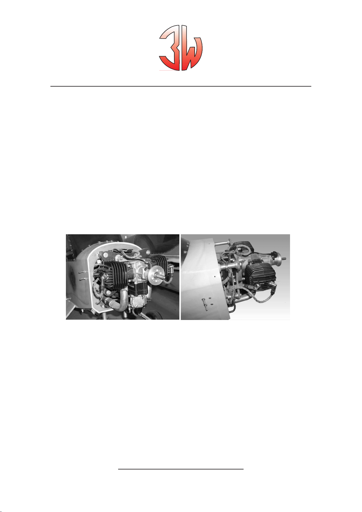
Engine in pusher operation:
Impor
t
ant
note!
When
engines
are
used operating
in
pusher
configuration cooling
ge
ts critical
and
special
attention
has
to
be
given
to
an
e
f
fective
cooling
method. A
good cooling
system
layout
depends
on
the actual
location (position)
of
the engine
in
the fuselage.
Operating temperature
To be able to check the cylinder head temperature ( CHT ) a thermo element has to be installed which fits
under the spark plug ( M 10 thread ). Optimum operating temperature range : 180°C - 220°C. In this range
piston, spark plug and combustion chamber will be free of remains. Maximum temperature of 270°C should
not be exceeded. During a certain time at full speed the temperature could be 250°C.
Colour of the spark plug should be : light or middle brown. A grey / gray colour is a typical sign for over
heating. Temperatures above 270°C are critical and over 300°C, piston can seize and could completely
damage the engine.
Temperatures below 180°C create remains ( carbon ) on the piston crown. Increasing remains hit the
cylinder and cause abnormal running noises ( knocking ) which will increase the load of the needle
bearings and can destroy them. Under extreme conditions the crankshaft can break and a complete
damage of the engine will be the result.
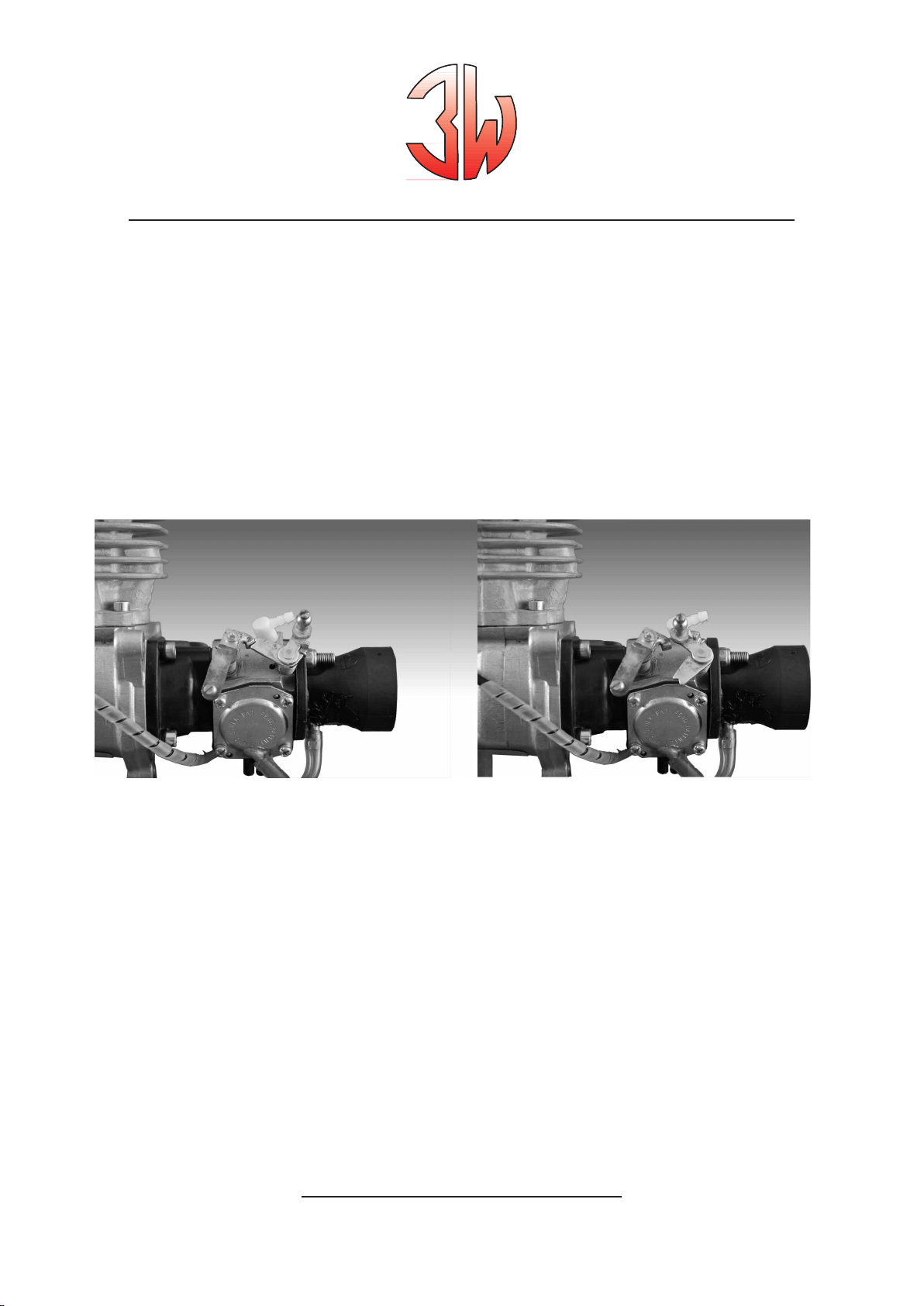
Rear induction
Carburetors, whether
front or
rea
r, require
a
steady
supply
of
fresh
air.
The
best
way
to
supply
air
to
a
rear
carburetor
is
by
ins
t
alling
an
air
scoop.
Some have
thought
to
drill
holes
into
the
fuselage
near
the carburetor
area
rather than creating
an
air scoop
for
the carburetor. This does
not
work,
it
fact
it
will
create
a
vacuum
e
f
fect that
will
draw the
air
away
from
the
carburetor!
Again,
you should
ins
t
all
an
air scoop
into
the
front of
the plane
which
will
supply air
into
the fuselage.
This
air
will
then
need
to flow
out
of
the fuselage.
Drill
exit
holes
into
the
rear
area
of
the fuselage
for this
purpose. Impor
t
ant:
The
interior of
the fuselage
must
be sealed
to
prevent
damage
from
gasoline
that
sprays
from
the carburetor.
Use
a
thin
epoxy
or
other appropriate
fuel proofing
method.
Do
not overlook
this
step
as
gasoline
will
melt some materials
like
S
tyrofoam
very
quickl
y.
www.3w-modellmotoren.com

120 - 150i B2 / TS / CS front and rear Engine Manual
Ignition
Consideration
needs
to
be
given
to
the placement
of
the
electronic
ignition
module. A
void placing
the module
in
the
p
ath
of
hot
air. Mount the
ignition
module
using
the
four
supplied
rubber gromme
ts
so
as
to
create
a
1/16"
gap
between
the
ignition
module and the
mounting
surface. Without
this
1/16"
gap the
ignition
module can overheat. Impor
t
ant: If
the
electronic
ignition
overhea
ts
it
will
malfunction
(e.g.,
backfiring
or shutting
down).
Ignition details:
•
The
red cable
is
positive
(+)
•
The
ignition timing
has
been
set at
our factory
•
When
fitting
a
new
ignition
it
is
impor
t
ant
to
achieve the
correct coordination
of
the sensor(s)
to
the
magne
ts
Refer to our special ignition description for further information
Canister mufflers
To
prevent
damage
to
the
header(s)
a
flexible support
bracket
is
required
to
mount
the canister(s).
The
location
for this
bracket
should
be
at the
canister's
center
of
gravit
y.
3W
canisters
have
a
reinforcement
ring
at
this
location.
www.3w-modellmotoren.com

120 - 150i B2 / TS / CS front and rear Engine Manual
We
suggest creating
two
com
p
artmen
ts in
the
front
section
of
the fuselage
by
ins
t
alling
a
horizon
t
al
tray.
Fuel
t
anks, batteries, and other equipment can
be
mounted
on top
of this
tray;
the canister(s)
being
ins
t
alled below
it.
Close
o
ff
the lower com
p
artment at
i
ts
rear
with
an
angled former. Locate
this
former
1"
behind the back
of
the canister(s).
Next
cut
a
hole
in
the
bottom
of
the fuselage
just
under the
rear
of
the canister(s). In
this
way
the
air coming from
the
front of
the model can
flow
over the canister(s) and then
be
deflected
by
the angled former
so
as
to
exit through
the hole
in
the fuselage.
Do
not forget
to
reinforce
around
this
hole.
Important:
This exit area needs to be four times (4x) as large as the intake area.
Propellers
•
Only use
propeller
brands and sizes
that
are
approved
for
your
engine
•
The
propeller
blades
must
be
of
the
same
length
•
The
propeller must
be
flat
(Y
ou
can check
for
flatness
by
putting
the
propeller on
a
level
surface.
The
maximum
di
f
ference
of
the blade heigh
ts
should
be
no
more than
1/64".)
•
The
propeller
ti
ps must
have an
identical
shape.
This
is
especially
impor
t
ant when
using
3
or
4
blade propellers.
•Y
ou must
use
a
drill
press
to
drill
your
propeller.
•Y
ou must
drill
the
propeller from
the
rea
r.
•
A
drill
guide
is
recommended,
but
the
propeller
washer can
be
used
as
a
drill
template. (Fix
the
propeller
washer
onto
the
propeller
in
the center-bore
using
a
bolt
and
nut.
Drill
one
hole; put
one
of
the
propeller
bolts into
the hole. Continue
until
the
last
bolt
is
used.)
•
If you
cannot hand
tighten all
of
your prop
bolts
easily then
you
have
not
drilled
the
propeller
correctl
y. This can
lead
to
sheared
propeller
bol
t
s.
•
Balancing
your propeller
is
absolutely
critical to
the health
of
your
engine.
Y
ou must
keep
your propeller
balanced. (Propeller balancers
are
available
from
DUBRO,
and others.)
•
Always
remember
that
when the engine
is
running
every person
must s
t
ay
behind the
line
of
the
ro
t
ating propeller;
never
to
the side
or
the
front!
Carburetor settings
Before
each
engine
is
shipped
it
has
to
p
ass
QC
and
is
then
test
run.
We
do
a
basic adjustment
of
the carburetor
needles
at
that point.
www.3w-modellmotoren.com

120 - 150i B2 / TS / CS front and rear Engine Manual
please
refere
to
t
able
of
tecnical
specifications
Important:
Do
not
remove the carburetor
spring
as
the
spring
hel
ps
keep
the carburetor
butterfly
aligned
properl
y.
Merely release
the ends
of
the
spring so that
it
no longer holds
the
butterfly
closed.
Carburetor Linkage
Included
with
your
engine
is
a
me
t
al bracket
to
extent
your
carburetor
pushrod
horn. Fix
this
bracket
onto
the carburetor
horn
with
a
2.6m
machine screw and
nut.
Then
solder
the arm
in
place.
Refer
to
the at
t
ached
illustration.
Note:
The
use
of
a
so
ft
pushrod
for
the
throttle
(plastic
or
nyrod)
is
not
recommended.
Use
a
me
t
al
or
carbon
fiber pushrod
with
a
plastic ball
joint
or
plastic clevis
at
each end.
This
will
keep
your
RPM
much more
consistent
and accurate around
idle
where
it
really
coun
t
s.
Engine Break In
•
Use
a
2-stroke petroleum
based
oil
(preferably ashless)
as
this
type
of
oil
has
a
good
honing
e
f
fect which
hel
ps
to
break
in
the engine
•
Use
a
mixture
of
32-1
or
even
30-1
•
Use
this
fuel mixture
for
approximately
2-3
hours
of
run
time
•
Use
a
high
Oc
t
ane
unleaded
fuel
(from 92
Oc
t
ane
is
ideal)
www.3w-modellmotoren.com

120 - 150i B2 / TS / CS front and rear Engine Manual
We
suggest
s
t
arting
the break
in
process
of
the engine
on
a
test s
t
and;
for
approximately one
hou
r. This time
should
be
used
to
get
familiar
with
the engine.
Do
not run
the engine at
full
throttle
for
more than ten seconds
during
this
test s
t
and break
in.
The
reason
for this
is
that you
are
not
getting
the normal
cooling
e
f
fect that you would
if
the engine
was
in
a
model
that
was
flying.
Another method
that
can
be
used
for
break
in
would
be
to
set the engine
between
2000-2500
rpm
and
let
it
run
for
4
hours.
A
f
ter
that
the engine
would basically
be
broken
in.
Note: For break-in
a
smaller
propeller
is
recommended.
Important:
Remember
that
when the engine
running
ever
person
must s
t
ay
behind the
line
of
the
ro
t
ating propeller;
never
to
the side
or
the
front!
A
f
ter
Initial
Break In
•
Use
high
grade
fully
synthetic
2-stroke
oil
•
Use
the
oil
manufacturer's recommended gas
to
oil
mixture
•
Use
a
high
Oc
t
ane
unleaded
fuel
(from 92
Oc
t
ane
is
recommended)
•We
use
3W
2-stroke
oil
in
our
engines
here
in
German
y,
but
there
are
other
high
grade
2-stroke
oils
that
will
perform well.
Note:
The
engine needs
12-20
hours
running
time
for
the break
in
process
to
be
100%
complete.
www.3w-modellmotoren.com

120 - 150i B2 / TS / CS front and rear Engine Manual
Additional installation notes
•
There
must
be
a
minimum
4"
se
p
aration
between
anything
at
t
ached
to
the receiver and
all
things
related
to
the
ignition
(i.e.,
the
ignition
i
t
self, and
i
ts
wires, battery, and
switch)
•
Use
a
plastic spiral
sheath
to
protect
the
ignition
cables
•
Never
remove the
sparkplug
cap
by using
a
mechanical aid
like pliers.
Only remove the
cap
by
hand
using
a
twist/pull
movement.
•
The
sp
ark
plug
cap
must
be
firmly
seated
to
the
sp
arkplug.
If
the
sp
ark
plug
cap
is
not
firmly
seated
there
is
a
very
good
possibility
that you
will
experience
radio
interference.
•
Use
only
ignition
on/o
ff
switches
recommended
by
3W
•6
volts
is
required
for
the
ignition.
•
Do
not skimp on your
throttle
servo. A
high quality
throttle
servo
is
recommended
for
reliable
and accurate operation
of
the carburetor.
•
Never
fill
the
fuel
t
ank via the carburetor
fuel line
•
Use
the
same
I.D.
for
t
ank
ventilation
and the carburetor
fuel line
•
Use
small
plastic
cable
ties on all fuel line
to
fitting
connections.
•We
recommend
cutting
the
fuel line
in
the
fuel
t
ank
in
half. And, then
joining
them back
together
with
a
brass tube.
The
brass tube preven
ts
a
folding of
the
fuel line
with
could
cut
the
fuel supply
for
the engine
(see
t
ank photo).
•
The
use
of
soldered
on
DUBRO
barbs
on
the ends
of
the brass
tubing
is
highly
recommended.
Again, always secure the
fuel line
with
small
plastic
cable ties.
Warning!
Failing
to
read
and
follow
all
of
the
instructions in this
manual can
lead
to
unsafe
conditions
and
damaged
equipment.
Here are
some examples:
•
Unbalanced
propellers
can
damage
the engine's
ball
bearings,
needle
bearings,
even
www.3w-modellmotoren.com

120 - 150i B2 / TS / CS front and rear Engine Manual
cause
the cranksha
ft
to
break
•
Incorrectly
drilled
propellers
can
lead
to
sheered
propeller
bolts
further
leading
to
acciden
ts
and crashes
•
Loose
propeller
bolts
can also
lead
to
sheered
propeller
bolts
further
leading
to
acciden
ts
and crashes.
Check
these
bolts
before
s
t
arting your
engine.
•
Flipping
the
prop
with
your
hand
or
fingers
can
lead
to
serious
acciden
t
s!
Always use
a
rubber
stick to
s
t
art the engine!
•
Not having the plane secure can
be lead
to
serious
acciden
t
s. Depending
on
i
ts
size
use
one,
two,
or
more helpers
to
secure
your
model. Always
tell
your
helpers
to
be
ready
for
the model
to
s
t
art at
full
power.
Remembe
r, these engines
have
a
high
power
output.
•
Do
not put your
finger(s), any items,
or
any other
p
ar
ts of
the
body
into
the
ro
t
ating
propeller.
•
Never
tune the carburetor
whilst
engine
is
running!
S
top
the engine.
T
une the carburetor
and
s
t
art the engine
again.
Repeat
this
procedure
until
the carburetor
is
properly
tuned.
•
Make
sure
that no
gasoline
will
be
splashed
into
the
hot
mu
f
fler(s).
•
Only
3W
mu
f
flers,
or
mu
f
flers
authorized
by
3W
with
an accep
t
ance
(test) number,
should
be
used.
•
Only
3W
-ignition
systems
should
be
used
for
proper operation.
Important:
Using unauthorized
produc
ts or failing to follow
the
instructions in this
manual
will
void your
warranty immediately.
Pilots check list
We
strongly
recommend checking the
following
agenda
for
your
own safety before
s
t
arting!
•
Check
the
propeller
bolts for
tightness
•
Check
that
the
spinner
is
firmly
at
t
ached
•
Check
the
propeller
for
possible
damage
•
Check
to
be
sure
you
have
the
throttle position
at
idle
•
Check
all
batteries
•
Check
servo
functions
•
Check
to
see
that
the
ignition
switch
is
OFF
•
Check
pressure
(6-8
bar)
system
of
retract
(if
applicable)
•
Check
all
linkages
for
play
•
Check
your
wheels
for
possible
damage
and
easy
running
www.3w-modellmotoren.com

120 - 150i B2 / TS / CS front and rear Engine Manual
•
Check
the
wing mounting
for tight
fit
and proper at
t
achment
•
Check
the canopy
for tight
fit
and proper at
t
achment
•
When
s
t
arting
the engine one person (minimum) has
to
hold
the model
Starting Procedure
If you
have read
and
understood
this
entire
manual,
and
followed
i
ts
recommendations,
you
are
ready
to
s
t
art
your
new
engine.
•
Use
a
rubber
stick to
s
t
art the engine.
Never
use
your
hand
or
fingers!
•
Insure
that your
receiver batteries
are
charged and
your
receiver
is
on
•
Insure
that your
ignition
battery(s)
are
charged
•
Insure
that your transmitter
is
on, and
that your
throttle
is
set
to
low
•
Insure
that your
plane
is
properly
and safely anchored
(use one,
two,
or
more people
if
necessary)
•
Close the choke(s)
•
Switch
on
the
ignition
•
Flip
the
propeller
until
the engine
"po
p
s"
(s
t
ar
ts
and
sto
ps quickly)
•W
ait
for
the
propeller
to
stop spinning,
turn
o
ff
the
ignition,
and open the choke(s)
•
Switch the
ignition
back
on
•
Flip
the
propeller
again
until
the engine
s
t
ar
ts
•W
arm-up the engine
for
at least
20
seconds
•
Due
to
the
high
power and torque
of
the engine(s)
it
is
not
recommended
to
open the
throttle
abruptly
Precision tuning of the carburetor
The
use
of
a
t
achometer
is
highly
recommended. And,
again,
never
adjust
the
needles
while the
engine
is
running!
1.
Using the
t
achometer tune the engine
for
maximum power
with
the
high
needle
(H).
2.
Again
using
the
t
achometer;
richen
the
high
needle
(H)
until
the
motor runs
100-200 RPM
less than the maximum
RPM.
Now
you
are
tuned
slightly rich
on
the
high
needle
(H).
3.
Let the engine
run
at
idle
for
one minute.
Check
to
see
that
the
idle
RPM
remains
cons
t
ant.
4.
If
the
idle
RPM
drops
until
the engine
sto
p
s;
the
low
needle (L)
is
too rich.
Lean
the
low
needle (L)
until
a
cons
t
ant
idle
RPM
is
achieved.
5.
Check
the
transition
with
a
quick
throttle
advance.
The
engine
should not sound
strained
www.3w-modellmotoren.com

120 - 150i B2 / TS / CS front and rear Engine Manual
at any time.
It should sound like
it
is
making
quick
steady power;
without
any hesi
t
ation.
6.
An
optimally
tuned engine
will
feel
a
bit
rich
a
f
ter
a
cold s
t
art.
It
will
s
t
art
to
run
right
a
f
ter
it
has
warmed
up
for
approximately one minute.
Trouble Shooting
Problem
The
engine
is
flooded
(the cranksha
ft
housing
is
filled with
fuel).
Solution
Remove
the
sp
ark
plug; turn
the engine
to
a
position
where
the
fuel runs out.
The
engine
s
t
ar
ts
a
f
ter being choked
but
then
sto
ps soon
a
f
ter.
The
low
needle
on
the carburetor
is
probably too
lean.
Go
back
to
the recommended
settings
and
adjust your
carburetor
from
there. This problem
may
also indicate
a
dirty
carburetor
or
faulty
ignition.
The
engine
runs rough
and
is
vibrating
strongl
y.
Balance
the propeller.
Check
the
ignition
timing.
Check
your plumbing
for
air/fuel leaks.
Check
your sp
ark
plug
for
carbon and check the
sp
ark
plug
gap. Check
the
motor mount
to
be
sure
it
is
rigid.
Check
to
make
sure the engine
is
mounted
on
a
level surface
so that
the
crankcase
is
free
of
tension.
Check
the engine and
propeller
bol
t
s.
The
engine
doesn't
reach
a
normal
RPM
at
full
throttle.
Check
the carburetor
settings.
Check
to
see
if
the
propeller
is
too
large.
V
erify that you
have
the
correct
mu
f
fler
system.
Check
to
see
if
the engine
is
overheating.
Check
the
ignition
timing.
Check
the
sp
ark
plug
for
defect.
V
erify you
have
the
correct
gasoline,
oil,
and
have
mixed them
with
the
correct ratio.
www.3w-modellmotoren.com

120 - 150i B2 / TS / CS front and rear Engine Manual
Metrics
www.3w-modellmotoren.com

120 - 150i B2 / TS / CS front and rear Engine Manual
mounting bolt pattern
rear
induction
ATTENTION:
This drawing
is
in original
size. Disable any
Acrobat
print setting to
fit
it
into
p
aper
size. Check the
printed p
attern before
drilling.
www.3w-modellmotoren.com

120 - 150i B2 / TS / CS front and rear Engine Manual
mounting bolt pattern
front
induction
ATTENTION:
This drawing
is
in original
size. Disable any
Acrobat
print setting to
fit
it
into
p
aper size.
Check the
printed p
attern before
drilling.
www.3w-modellmotoren.com

120 - 150i B2 / CS / TS rear and front
Engine Manual
Techn. specifications / Caracteristiques techniques
Engine Cylinder Power / Bore dia. / Stroke / Speed range / Weight / Propeller Propeller carburetor
capacity HP / kW in in rpm lbs 2-bladed 3-bladed settings
cu.in
120i B2
7.92 11,5 / 8,5 1.8 1.42 1200 - 8500 8.47
28x10,28x12
26x12,27x12; 28x10
High
= 2 1/4
F
30x10,30x12
Low
= 2 1/2
120i B2
7.92 11,5 / 8,5 1.8 1.42 1200 - 8500 8.84
28x10,28x12
26x12,27x12; 28x10
High
= 2 1/4
R
30x10,30x12
Low
= 2 1/4
140i B2
8.39 13,5 / 10,0 1.88 1.49 1200 - 8500 8.42
28x12,30x10;
30x12,
26x14; 27x12;
27
x
13 W
albro:
H= 2 1/4
F
32x10
Low
= 2 1/4
T
illi
t
son:
H = 3/4
Low
= 1 3/4
140i B2
8.39 13,5 / 10,0 1.88 1.49 1200 - 8500 8.82
28x12,30x10;
30x12,
26x14; 27x12;
27
x
13
High
= 2 1/4
R
32x10
Low
= 2 1/4
150i B2
9.19 16,5 / 12,1 1.93 1.57 1200 - 8500 7.69
28x12, 30x10, 30x12, 28x12, 29x12,
30x10
W
albro:
H= 2 1/4
F
32x12
Low
= 2 1/4
T
illi
t
son:
H = 3/4
Low
= 2
150i B2
9.19 16,5 / 12,1 1.93 1.57 1200 - 8500 8.44
28x12, 30x10, 30x12, 28x12, 29x12,
30x10
High
= 3/4
F / TS
32x12
Low
= 2
150i B2
9.19 16,5 / 12,1 1.93 1.57 1200 - 8500 8.45
28x12, 30x10, 30x12, 28x12, 29x12,
30x10
High
= 2 1/4
R
32x12
Low
= 2 1/4
150i B2
9.19 16,5 / 12,1 1.93 1.57 1200 - 8500 9.21
28x12, 30x10, 30x12, 28x12, 29x12,
30x10
High
= 2 1/4
R / TS
32x12
Low
= 2 1/4
Universal Specifications
• Crankshaft 3
Ball
bearings
• Connection rod
• Gasoline Version www.3w-modellmotoren.com
Needle
bearings
on
both
ends
à
unleaded
fuel
(9
2
Oc
t
ane
is
recommended)

120 - 150i B2 / TS / CS front and rear Engine Manual
Garantie-Bedingungen Conditions de garantie Condiciones de la Garantía
Wir
geben
auf unsere
Geräte
36
Monate
Nous
donnons
une garantie
de
36
mois
Ofrecemos una garantia
de
36
ano
V
ollgarantie
ab
V
erkaufsdatum.
à
compter
de
la
date de vente. Cette desde
la fecha
de
compra, que
será
Die Garantie
ist
ausschliesslich
garantie est limitée exclusivement
au
aplicable única
y
exclusivamente
a
la
beschränkt auf den kostenlosen
Ersatz
remplacement
gratuit
des pièces
reposición gratui
ta
de piezas
defekter
T
eile,
deren Mängelursache défectueuses
dont
la
cause
est
à
correspondientes
a
fabricación o
Konstruktions
oder Materialfehler
sind. imputer
à
un
défaut
de
matériel
ou
de
materiales defectuosos.
Recuérdese
Wir möchten
ausdrücklich
darauf
fabrication.
Nous tenons
à
préciser que que la
garantía
sólo
será
efectiva
si
se
hinweisen, dass die
Garantie
nur
dann la garantie
n'est
valable que
si
le adjunta al
a
p
arato
a
re
p
ara
r.
erfüllt wird,
wenn der Garantieanspruch document
de
garantie est remis
avec
la
No se
admitirá ninguna reclamación
gleichzeitig mit
dem demande de ré
p
aration. Nous
ne
por
No se
admitirá ninguna
Re
p
araturau
f
trag geltend gemacht
wird. pouvons p
as
accepter une
ré
p
aration reclamación
por correc
t
amente
las
Beachten
Sie
auch
bitte,
dass
wir
einen
en
garantie
lorsque
la défectuosité est
instrucciones
de
funcionamiento,
o
Garantieanspruch
nicht
akzeptieren
à
imputer
au
nonrespect des bien debidos
a
un
mal
manejo,
al
uso
können, wenn die
S
törung durch prescriptions
d'emploi,
à
une usure
de piezas de
recambio inapropiadas
unsachgemässe Behandlung
(siehe
normale,
à
l'emploi
de
pièces
de
o
re
p
araciones efectuadas
por
Gebrauchsanweisung),
durch natürliche
rechange
non
appropriées
ou
à
des inexpertos.
Abnutzung,
durch
V
erwendung fremder
ré
p
arations
e
f
fectuées per tierces Por favor, pida
a
su
vendedor que
Ersatzteile oder
Re
p
araturen
durch
personnes.
Faites
remplir
cette carte
de
cumplimente
es
ta
garantía en
el
andere en
t
stehen. Lassen
Sie
auf garantie
p
ar
le négociant
ou
at
t
achez
momento
de
la compra. Conserve
dieser Garantiekarte das Kaufdatum
votre
quit
t
ance
à
ce
document. cuidadosamente
este
certificado
ya
que
durch
den
Händler
eintragen, oder
Conservez avec
soin
ce
certificat
car cualquier reclamación
sólo
será
válida
he
f
ten
Sie
die
Kaufquittung
dazu.
votre
droit
de
garantie
en
cas
de
mediante la presen
t
ación
de este
Bewahren Sie
diese Garantiekarte réclamation
n'est
valade
que
sur
documento.
sorgfältig
auf, denn ein Garantieanspruch présen
t
ation
de ce
document.
ist
leider
hinfällig,
wenn sie
Esta garantla vale solo si presentada
bei einer Reklamation
nicht
vorgelegt
Cette garantie est valable seulement junta a la prueba de cuempra (recibo
worden kann.
si accompagnée d'une preuve de pago).
d'achat (Facture du revendeur).
Diese Garantie ist nur gültig, wenn
sie zusammen mit einem Kaufsbeleg
vorgewiesen wird (Ladenquittung).
www.3w-modellmotoren.com
Guarantee conditions
We
grant
a 36
month
guarantee as
from
purchase
date.
This
guarantee
applies
solely
to
the
free
replacement
of
defective
p
ar
ts
resulting from faulty
material
or
manufacturing.
We
point out
that
guarantee
is
e
f
fective
only
if
joined
to
the
ap
p
aratus
to
be re
p
aired.
Na
claim conceming
a
defect caused
by
noncompliance
with
operation
instructions,
mishandling,
unsui
t
able
sp
are
p
ar
ts
and
unskilled
re
p
ars
will
be
acknowledged.
Plese
ask
your
dealer
to
fill
in this
guarantee
at time
of
purchase.
Keep
this
certificate carefully
because
your
claim
is
valid only upon
presen
t
ation of
this
document.
This guarantee is valid only when
accompanied with the official shop
receipt.
Condizioni di garanzia
Riconosciamo una
garanzia
di
36
mesi
dalla
date
di
acquisto.
Ques
ta
garanzia
si
limi
ta
esclusivamente
alla
sostituzi
-
one
gratui
ta dei
pezzi
difettosi
la
cui
causa
è
da
impu
t
are
a
difetti di
materi-
ale
o
di
fabbricazione. Desideriamo
precisare che la
garanzia
è
valida
solamente
se
la stessa accom
p
agna
l'app
arecchio
per la
ri
p
arazione. Non
possiamo
accet
t
are
una
ri
p
arazione
in
garanzia
quando
il
difetto
è
impu
t
abile alla
non
osservanza delle
istruzioni d'uso,
manomissioni,
all'impiego
di
pezzi
di
ricambio non
adatti
o
a
delle
ri
p
arazioni
eseguite
da
terzi.
Fate
compilare
questo
certificato
di
garanzia
dal
vostro
negoziante al momento
dell'acquisto
dell'ap
p
arecchio. Conservate
con
cura
questo
certificato
perché
il
vostre
diritto
di
garanzia
è,
valido solo contro
presen
t
azione
di
questo documento.
Questa garanzia è valida solo se
presentata
assieme alla prova d'acquisto.
(Ricevuta del negoziante).
Condiçoes de garantia
Reconhecemos
uma
garantia
de
36
meses da da
ta
de
compra.
Es
ta
garantia
é
limi
t
ada
exclusivamente
à
substituição grátis
de peças
com
defeitos
de
material
ou
de
fabricação.
Desajamos
recordar que
a
garantia
só
tem
valor
se
acom
p
anha
o
a
p
arelho
a
re
p
ara
r.
Nao
podemos
acei
t
ar uma re
p
aração
em
garantia
se
o
defeito
resul
ta
da
fal
ta
de atenção às
instruçoes
de
uso,
manejo,
errado, emprego
de peças de
troca
nao apropriadas
ou
a
re
p
arações
fei
t
as
por
terceiros.
Queira
pedir
ao
seu vendedor
de
compilar
este
certificado
de
garantia
ao
momento
da
compra
do
a
p
arelho.
Guarde este
documento com cuidado
pois
a
garantia
só
vem
oferecida
contra
a
apresen
t
ação da
certificado
de
compra,
além
do recibo
da
loja.
Esta garantla só vale se for
apresentada junta à prova de
compra (recibo da loja).
This manual suits for next models
7
Table of contents
Other 3W Toy manuals
Popular Toy manuals by other brands

REVELL
REVELL German Submarine Type VII C/41 manual

Hasbro
Hasbro Jurassic Park III JP3 instructions

Eduard
Eduard Panther Ausf. D Zimmerit Vertical quick start guide

REVELL
REVELL 04836 manual

Faller
Faller PETROL STATION WITH SERVICE BAY instructions

Dancing Wings Hobby
Dancing Wings Hobby Cessna150 Assembly instructions