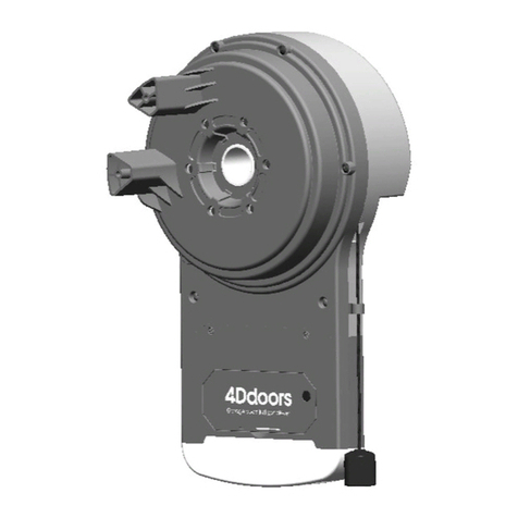
4Ddoors CX1024 Manual

www.4ddoors.com.au
instructions for fitting, operating and maintenance
Sliding operator
CX1024

2
A
B
Ø 12 mm
Ø 5,5 mm
17 mm
3 mm
2
17
5 mm
3 mm
PIC 01

3
200
343
178
226
334
3 328
200
343
160
74
50
100
128
206
283
D1
28
36
17.5 7.5
6.5
37
25
30
6 8.7
9
450 450
52 1004
6.5
17.5
7.5
40
28
240
920
100
1020
240100
240 920
100 240100
1020
C
6 x 6 x
438 634
438 632
438 631
2901624
D2
D3
D4
108
PIC 01

ENGLISH 4
Table of contents
1 ABOUT THIS MANUAL 5
2 NOTES 5
2.1 Applicable documents . . . . . . . . . . . . . . . . .5
2.2 Intended use. . . . . . . . . . . . . . . . . . . . .5
2.3 Unintended use . . . . . . . . . . . . . . . . . . .5
2.4 Installer qualifi cation. . . . . . . . . . . . . . . . . .5
2.5 Warning notices used . . . . . . . . . . . . . . . . .5
2.6 International colour code in accordance with IEC 757 . . . . .5
2.7 Symbols used . . . . . . . . . . . . . . . . . . . .5
3 SAFETY INSTRUCTIONS 6
3.1 Safety instructions for installation, maintenance, repair and
disassembly of the gate system . . . . . . . . . . . . .6
3.2 Safety instructions for installation. . . . . . . . . . . . .6
4 INSTALLATION 7
4.1 Checking and preparing the gate/gate system. . . . . . . .7
4.2 Installing the sliding opener . . . . . . . . . . . . . . .7
4.3 Gear rack installation . . . . . . . . . . . . . . . . .9
4.4 Installing and adjusting the end position magnets . . . . . .11
5 COMMISSIONING/CONNECTING ADDITIONAL
COMPONENTS 13
5.1 Information on electrical work . . . . . . . . . . . . . .13
5.2 Electrical connection of the opener . . . . . . . . . . . .13
5.3 Connecting the warning lights . . . . . . . . . . . . . .13
5.4 Connecting external lighting. . . . . . . . . . . . . . .14
5.5 Command inputs . . . . . . . . . . . . . . . . . . .14
5.6 Stop input . . . . . . . . . . . . . . . . . . . . . .14
5.7 Light barrier connection . . . . . . . . . . . . . . . .14
5.8 Closing edge protection . . . . . . . . . . . . . . . .15
5.9 Radio receiver . . . . . . . . . . . . . . . . . . . .15
6 STRUCTURE OF THE CONTROL 16
6.1 Display indicators . . . . . . . . . . . . . . . . . . .16
6.2 The and function buttons in normal mode . . . . . . .16
6.3 Buttons in programming mode and menu structure . . . . . .16
6.4 Programming mode (main menu 1) . . . . . . . . . . . .16
6.5 Settings in the function menu . . . . . . . . . . . . . .17
6.6 Settings in the time menu. . . . . . . . . . . . . . . .17
6.7 Settings in the value menu . . . . . . . . . . . . . . .17
6.8 Loading the standard values (main menu 5) . . . . . . . .17
6.9 Starting the self teach-in function for the run times
(main menu 4) . . . . . . . . . . . . . . . . . . . .17
7 CONFIGURING THE CONTROL 18
7.1 The confi guration menu . . . . . . . . . . . . . . . .18
7.2 Gate partially open position (pedestrian access) . . . . . . .19
7.3 Opening direction of the gate . . . . . . . . . . . . . .19
7.4 Pre-warning period warning light (terminals E4/E5)
in the open direction. . . . . . . . . . . . . . . . . .19
7.5 Pre-warning period warning light (terminals E4/E5)
in the close direction. . . . . . . . . . . . . . . . . .19
7.6 Running speed in the open direction . . . . . . . . . . .19
7.7 Running speed in the close direction . . . . . . . . . . .20
7.8 Soft running speed . . . . . . . . . . . . . . . . . .20
7.9 Start-up suppression . . . . . . . . . . . . . . . . .20
7.10 Warm-up ramp in the open direction . . . . . . . . . . .20
7.11 Warm-up ramp in the close direction . . . . . . . . . . .20
7.12 Soft stop in the open direction . . . . . . . . . . . . . .21
7.13 Soft stop in the close direction . . . . . . . . . . . . . .21
7.14 Start pulse (terminals J1/J4) when the gate is opening . . . .21
7.15 Start pulse (terminals J1/J4) when the gate is closing . . . . .21
7.16 Start pulse (terminals J1/J4) when the gate is opening . . . .22
7.17 Start pulse (START P, terminals J2/J4)
with pedestrian opening . . . . . . . . . . . . . . . .22
7.18 Automatic closing . . . . . . . . . . . . . . . . . . .22
7.19 Quick close after passage . . . . . . . . . . . . . . .22
7.20 Quick close after passage of both light barriers . . . . . . .22
7.21 Warning light (terminals E4/E5) during the pause time . . . .23
7.22 Command inputs (terminals J1/J4, J2/J4) function . . . . . .23
7.23 Stop input (terminals J3/J4) . . . . . . . . . . . . . . .23
7.24 Photocell 1 input (terminals J5/J9) . . . . . . . . . . . .24
7.25 Photocell 2 input (terminals J6/J9) . . . . . . . . . . . .24
7.26 Testing the safety devices . . . . . . . . . . . . . . .24
7.27 Closing edge protection 1 (terminals J7/J9) input . . . . . .24
7.28 Closing edge protection 2 (terminals J8/J9) input . . . . . .25
7.29 Evaluation of the closing edge protection. . . . . . . . . .25
7.30 Obstacle sensor in the open direction . . . . . . . . . . .25
7.31 Obstacle sensor in the close direction . . . . . . . . . . .25
7.32 Obstacle sensor in the open direction . . . . . . . . . . .26
7.33 Obstacle sensor in the close direction . . . . . . . . . . .26
7.34 Function of the option relay (terminals B1/B2) . . . . . . . .26
7.35 Radio receiver channel 2 function . . . . . . . . . . . .27
7.36 Warning/signal light output function . . . . . . . . . . . .27
7.37 ADI interface. . . . . . . . . . . . . . . . . . . . .27
7.38 End of programming. . . . . . . . . . . . . . . . . .27
7.39 Reading the cycle counter . . . . . . . . . . . . . . .28
7.40 Indicating maintenance due . . . . . . . . . . . . . . .28
8 OPERATION 29
8.1 Instructing personnel . . . . . . . . . . . . . . . . .29
8.2 Function check . . . . . . . . . . . . . . . . . . . .29
8.3 Conduct in the event of/following a power failure. . . . . . .29
9 INSPECTION, CHECKS AND MAINTENANCE 30
10 MALFUNCTIONS 31
10.1 LED MAINS does not switch on . . . . . . . . . . . . .31
10.2 LED OVERLOAD switched on . . . . . . . . . . . . . .31
10.3 Extended pre-warning period . . . . . . . . . . . . . .31
10.4 Opener runs at minimum speed in the open and close direction 31
10.5 The gate does not open or close fully . . . . . . . . . . .31
11 LOADING THE ERROR MEMORY (MAIN MENU 3) 31
12 ERROR TABLE 32
13 "-PRG" MENU FUNCTION OVERVIEW 34
14 "-CNT" MENU FUNCTION OVERVIEW 36
15 "-ERR" MENU FUNCTION OVERVIEW 36
16 "-LRN" MENU FUNCTION OVERVIEW 36
17 "-DEF" MENU FUNCTION OVERVIEW 36
18 CONNECTION OVERVIEW 38
19 CABLE LAYING DIAGRAM 40
20 DISASSEMBLY AND DISPOSAL 41
21 OPTIONAL ACCESSORIES 41
22 WARRANTY CONDITIONS 41
23 TECHNICAL DATA 41
Transmission and reproduction of this document, utilisation and
communication of its content are prohibited without express authorisation.
Contravention of this rule could lead to obligation to pay compensation.
All rights reserved with regard to patent claims or submission of design or
utility patent. Subject to modifi cation.

ENGLISH5
1 ABOUT THIS MANUAL
▪ This manual is a translation of the original manual within the
sense of EC Directive 2006/42/EC. Read this manual carefully
and fully. It contains important information regarding the
product. Observe the information and, in particular, observe
the safety and warning information.
▪ Please keep this manual in a safe place!
▪ Instructions in languages other than German are translations
of this original manual.
2 NOTES
2.1 Applicable documents
The following documents must be available for the safe use and
maintenance of the gate system:
▪ This manual
▪ The manual for the sliding gate
2.2 Intended use
▪ The opener may be used for private and commercial
purposes.
▪ The sliding opener is only intended for operation of smooth-
running sliding gates. The maximum permissible gate size and
weight must not be exceeded.
▪ It must be possible to open and close the gate easily by hand.
▪ Please observe the manufacturer's information on possible
gate and opener combinations. Possible hazards within
the sense of DIN EN 13241-1 can be avoided by carrying
out construction and installation in accordance with our
specifi cations. Gate systems located in public areas which
are only equipped with one safety device, e.g. force limitation,
may only be operated under supervision.
2.3 Unintended use
▪ Continuous operation and use on gates with gradients or
slopes is not permitted.
▪The sliding opener must not be operated in areas at risk
of explosion.
▪ The opener is not designed for operating sluggish/stiff gates,
i.e. gates which cannot be opened or closed by hand, or only
with diffi culty.
2.4 Installer qualifi cation
Only correct installation and maintenance, carried out by a
competent/expert fi rm or individual in accordance with the
manuals can ensure that an installation will proceed safely and
as intended. In accordance with EN 12635, an expert is someone
with appropriate education, qualifi ed knowledge and practical
experience to correctly and safely install, check and maintain a
gate system.
2.5 Warning notices used
The general warning symbol indicates a hazard that
poses a risk of injury or death.
The general warning symbol in conjunction with the warning
levels described below are used in this manual.
DANGER!
Indicates a hazard which poses an imminent risk of death
or serious injury.
WARNING!
Indicates a hazard that poses a risk of death or serious
injury.
CAUTION!
Indicates a hazard that poses a risk of minor or moderate injury.
ATTENTION!
Indicates a hazard that poses a risk of product damage or
destruction.
2.6 International colour code in accordance with IEC 757
WH White GN Green
BN Brown YE Yellow
BK Black RD Red
OG Orange BU Blue
GY Grey VT Violet
RS Pink
2.7 Symbols used
2.5 = See Section 2.5
= Factory setting
Dear customer
We are delighted that you have chosen one of our quality products.

ENGLISH 6
3 SAFETY INSTRUCTIONS
WARNING!
Risk of injury from
unintentional gate movement!
In the event of improper
installation or operation of the
opener, unintentional gate
movements may be triggered
which may cause people or
objects to become trapped.
In the event of improperly attached control units (e.g. buttons),
unintentional gate movements may be triggered which may
cause people or objects to become trapped.
► Follow all instructions contained in this manual.
► Attach control units at a height of minimum 1.5 m (outside of
the reach of children).
► Install fi xed control units (e.g. buttons) within sight of the
gate but away from moving parts.
In the event of the failure of safety devices, persons or objects
may become trapped.
► In accordance with ASR 1.7, install at least one easily
identifi able and accessible emergency command device
(emergency stop) in the vicinity of the gate, which may be
used to stop the gate in the event of danger.
WARNING!
Risk of injury when the gate is moving!
A moving gate can give rise to injury or damage in the gate
area.
► Do not allow children to play on the gate system.
► Ensure that no persons or objects are located within the
movement area of the gate.
► In the event that the gate system is equipped with only one
safety device, operate the sliding opener only when you can
clearly see the movement area of the gate.
► Monitor movement of the gate until it has reached its end
position.
► Only pass or walk through gate openings of remote-
controlled gate systems if the gate is stationary!
► Never stand within the open gate.
3.1 Safety instructions for installation, maintenance,
repair and disassembly of the gate system
The installation, maintenance, repair and disassembly of the
gate system and the sliding opener must be performed by expert
personnel.
► In the event of the failure of the gate system or the sliding
opener (sluggishness or other faults), always commission
expert personnel immediately to inspect and repair the
system.
3.2 Safety instructions for installation
▪ The expert must ensure that the applicable regulations
concerning safety at work and rules on the operation of
electrical equipment must be observed during installation
work. To this end, the national guidelines must be followed.
Possible hazards per DIN EN 13241-1 can be avoided by
carrying out construction and installation in accordance with
our specifi cations.
▪ After completing installation, the installer of the gate must
declare conformity with DIN EN 13241-1 in accordance with
the scope of application.
▪ Before commencing electrical work, ensure that the
system is fully de-energised and secure it against
unauthorised re-activation.

ENGLISH7
4 INSTALLATION
ATTENTION:
IMPORTANT INSTRUCTIONS FOR SAFE INSTALLATION.
OBSERVE ALL INSTRUCTIONS, INCORRECT INSTALLATION
CAN LEAD TO SERIOUS INJURY.
4.1 Checking and preparing the gate/gate system
WARNING!
Risk of injury from gate system faults!
A fault in the gate system or an improperly aligned gate can
lead to serious injury.
► Do not use the gate system if repair or adjustment work
needs to be performed.
► Check the entire gate system (hinges, gate mounting and
fasteners) for wear and potential damage.
► Check for rust, corrosion or cracks.
The sliding opener is not designed for operating sluggish/stiff
gates, i.e. gates which cannot be opened or closed by hand, or
only with diffi culty.
The opener is only suitable for gates which do not exhibit
gradients or slopes.
The gate must be mechanically sound so that it can be easily
operated by hand (EN 12604).
► Check that the gate can be opened and closed properly.
► Put mechanical gate locks which are not required for operation
with a sliding opener out of operation. This includes, in
particular, the locking mechanisms of the gate lock.
► Secure the gate mechanically to prevent it from overrunning
its guides.
4.2 Installing the sliding opener
WARNING!
Risk of injury from unintentional gate movement
In the event of improper installation or operation of the opener,
unintentional gate movements may be triggered which
may cause people or objects to become trapped.
► Follow all instructions contained in this manual. Danger
of crushing and shearing! Never grab hold of the main or
secondary closing edges when the gate is moving!
4.2.1 Foundation for the sliding opener
ATTENTION!
Faults in the control lines
Control lines and supply lines routed together can lead to
malfunctions.
► Route the control lines of the opener (24 V DC) in a separate
installation system to the supply lines (230/240 V AC).
• A foundation must be cast for the sliding opener, as shown in
Figure 1. The marking indicates the frost-free depth
(in Germany = 80 cm).
• Concrete ≥ B25/C25 (compacted) is required.
• Gates with interior rollers may require a plinth foundation.
• The 230/240 V mains supply line must pass through an empty
conduit in the foundation. The supply line for connection of
24 V accessories must past through a separate empty conduit
separated from the mains supply line.
m
min. 550
min. 350
min. 225
A
24 V
230/240 V~
50 Hz
NYY-I 3 x 1,5 mm2
1
Figure 1 - Foundation
4.2.2 Inserting the base plate
Prepare the concrete foundation in accordance with the
installation dimensions. Secure the ground anchor in the holes
in the metal base plate and insert into the cement surface.
Always observe the installation dimensions! See “Figure 1 -
Foundation” and “Figure 2 - Ground anchor”.
The attachment base must be completely level and clean over its
entire length.
The screw threads of the fl oor anchor, as well as the empty
conduits/cables for electrical connection, must protrude fully.
WARNING!
Unsuitable fi xing materials
Use of unsuitable fi xing materials can lead to the opener being
insecure and coming loose.
• The installer must verify the suitability of the supplied
installation materials for the installation location.

ENGLISH 8
50 mm
A
70mm
2
E
D
Figure 2 - Ground anchor
Note
The foundation must be allowed to harden suffi ciently before
installation.
4.2.3 Fixing the motor base plate to an existing
concrete foundation
Before drilling the four holes, their position must be marked on
the surface of the foundation. Use the motor base plate as a
drilling pattern. Always observe the installation dimensions! See
“Figure 1 - Foundation” and “Figure 2 - Ground anchor”.
Then drill plug holes, clean the holes and fi x the base plate with
suitable installation materials. Ensure to tighten the nut and
washer to the ground.
ATTENTION!
Damage from dirt
Drilling dust and chips can lead to malfunctions.
► Cover the opener when drilling.
100mm + X
X
m
min. 225
A
3
Ø M10
Figure 3 - Heavy load anchor
4.2.4 Opening the opener housing
The cover of the housing must be opened for the sliding opener
to be installed.
ATTENTION!
Potential damage from penetrating moisture!
► Protect the control from moisture when opening the sliding
opener.

ENGLISH9
4.2.5 Installing the opener housing
• Remove the 4 nuts (D) and washers (E) used to fi x the base
plate to the ground anchors during foundation works.
• Cut the empty conduit seal (F) according to the connection
lines and install in the opener housing. Ensure that the holes
are not too large that insects may be able to crawl through.
• When positioning the housing on the fl oor anchors or on the
threaded rods of the heavy load anchor, pull the supply line
and other connection lines through the empty conduit seal into
the housing from below, ensuring that there is no warping.
• Position the opener on the threaded bolts of the base plate,
align parallel to the gate and adjust the height using the
4 height adjustment screws (G). Then fi x the opener motor.
G
E
D
F
4
Figure 4 - Fixing
Note
When tightening, ensure a level, stable and secure fi xing.
A minimum clearance of 5 mm between the anti-trap protection
and gate panel must be adhered to over the entire length of the
gate, see “Figure 5 - Aligning the opener”.
5
> 5 mm
D
97 mm
2 mm
0 - 20 mm
Figure 5 - Aligning the opener
4.3 Gear rack installation
Note
Unlock the sliding opener before installing the gear racks, see
“Figure 8 - Unlocking the opener”.
• Using the height adjuster, raise the opener by approx. 5 mm
and fi x the motor to the base plate.
• Unlock the opener.
• Rest the gear rack against the opener pinion and by sliding
the gate manually, install the gear rack metre by metre to the
gate. Fix the gate rack in alignment with the opener pinion.
• Adjust the opener using the height adjustment screws (G) so
that there is gap of 1 - 2 mm between the rack and pinion. This
prevents the weight of the gate from exerting a load on the
opener.

ENGLISH 10
ATTENTION!
Incorrectly installed or improperly aligned gear racks can lead
to malfunctions. The specified dimensions must be observed!
ATTENTION!
Damage from dirt and fl ying sparks
Drilling dust, chips and flying sparks can lead to malfunctions
and/or corrosion.
► Cover the opener when drilling and welding.
ATTENTION!
Use the plastic gear rack only on smooth-running gates and
gates intended for private use. The max. gate weight of 1000
kg must not be exceeded!
Note
In deviation from the fi gure, suitable connecting elements must
be used on other gate types (e.g. use corresponding woods
screws on wooden gates), diff erent screw-in lengths may also
be required. In deviation from the fi gure, the requisite core
hole diameter may vary according to the material thickness
or strength. The requisite diameter may be Ø 5.0 - 5.5 mm for
aluminium and Ø 5.7 - 5.8 mm for steel.
Ø 5-5,8
Art.-Nr. 438631
438632
≈1-2 mm
6
Figure 6 - Installing the plastic gear rack
Art.-Nr.2901624
min. 130 mm
max. 150 mm
≈1-2 mm
7
Figure 7 - Installing the steel gear rack
Note
When installing metal gear racks on a meter grid, ensure
that they are not installed fl ush, note the continuation of the
toothing. To check a gear rack, counter/hold it from below. See
“Figure 7 - Installing the steel gear rack”.

ENGLISH11
4.3.1 Actuating the emergency release
In the event of a power failure or malfunction, the opener motor
can be unlocked. To do this, proceed as follows:
• Turn the cover fl ap (K) over the lock to the side.
• Insert the key (I, supplied) into the lock and turn in a clockwise
direction to open the lock cover of the emergency release.
• Insert the triangular key (J, supplied) into the emergency
release lock and turn in a clockwise direction as far as it will go.
• The sliding gate can now be moved by hand.
To lock the opener again, proceed as follows:
• To lock, insert the triangular key (J, supplied) into the
emergency release lock and turn in an anticlockwise direction
as far as it will go.
• Move the gate by hand until it audibly engages.
• Close the lock cover of the emergency release and the cover
fl ap (K).
KIJ
8
Figure 8 - Unlocking the opener
KIJ
9
Figure 9 - Locking the opener
4.4 Installing and adjusting the end position magnets
WARNING!
Falling out
Overrunning the limit switches can cause the gate to fall out.
• A mechanical limit stop must be installed in the open and
closed end positions as an overrun protection.
Firstly, fi x the two magnet holders in the corresponding end
positions on the gear rack using the screws supplied. Then
install the magnets in the holders, ensuring that the red magnet
(SX) is installed on the left and the blue magnet (DX) is installed
on the right (see “Figure 11 End positions”). Determine the
correct distance to the two reed contacts. To do this, unlock the
opener and slide the gate into the gate open and gate closed end
positions.
Monitor the limit switch display on the control, if the gate open
or gate closed indicator appears, the magnet in the reed contact
has been detected. Move the magnet holders to correct. The
magnet holders can be permanently fi xed in place following a
successful test run.
Note
The correct distance between the magnet and reed contact
depends on the installation situation and cannot be determined
in advance, only by testing. The distance must be a minimum
of 38 mm, a larger distance can prevent magnet detection.
See “Figure 12 - Distances”.
Note
The opener must be adjusted such that the gate is not pressed
against the mechanical limit stop in the end positions and a
distance of approx. 10 - 30 mm is maintained.
Note
Seal the housing against moisture and insects. See “Figure
10 - Sealing”.
10
Figure 10 - Sealing

ENGLISH 12
DXSX
DXSX
11
Figure 11 End positions
Max 38 mm
102 mm
12
Figure 12 - Distances

ENGLISH13
5 COMMISSIONING/CONNECTING
ADDITIONAL COMPONENTS
5.1 Information on electrical work
DANGER!
Power supply
Contact with the power supply poses a risk of fatal electric
shock.
Always observe the following information:
► Electrical connections may only be established by a qualifi ed
electrician.
► The on-site electrical installation must comply with the
respective safety regulations (230/240 V AC, 50/60 Hz).
► Before commencing electrical work, ensure that the system
is fully de-energised and secure it against unauthorised re-
activation.
ATTENTION!
• Applying external voltage to the connection terminals of the
control system will destroy the electronics!
• To avoid malfunctions, ensure that the control lines of the
opener (24 V DC) are laid in an installation system separate
from the other supply lines (230 V AC)!
WARNING!
Risk of injury from
unintentional gate movement!
In the event of improper
installation or operation of the
opener, unintentional gate
movements may be triggered
which may cause people or
objects to become trapped.
In the event of improperly attached control units (e.g. buttons),
unintentional gate movements may be triggered which may
cause people or objects to become trapped.
► Follow all instructions contained in this manual.
► Attach control units at a height of minimum 1.5 m (outside of
the reach of children).
► Install fi xed control units (e.g. buttons) within sight of the
gate but away from moving parts.
In the event of the failure of safety devices, persons or objects
may become trapped.
► In accordance with ASR 1.7, install at least one easily
identifi able and accessible emergency command device
(emergency stop) in the vicinity of the gate, which may be
used to stop the gate in the event of danger.
5.2 Electrical connection of the opener
The mains connection (230 V AC/50 Hz) of the opener requires
a line NYY 3 x 1.5 mm2 (to 20 m supply line) or NYY 3 x 2.5 mm2
(to 30 m supply line). The supply line must be secured with an
ELCB (30 mA) in accordance with the statutory requirements.
In accordance with ASR 1.7, an all-pole-disconnecting lockable
main switch must be installed in the area of the opener between
the mains supply line and the supply line to the opener.
Connect the supply line to terminals L and N on the power board
and the protective conductor PE to the protective conductor
connection of the opener housing.
See "Figure 13 - Opener mains connection".
50-60 Hz
230Vac
LN
MAINS
13
Figure 13 - Opener mains connection
Note
The remaining accessories may only be connected following
a complete test run in conjunction with the motor control,
command unit and correct limit switch adjustment.
5.3 Connecting the warning lights
A warning light (e.g. SLK-L) may be connected to the control.
Connect the warning light (24 V DC/max. 3 W) to terminals E4
and E5 (not fl oating, 24 V DC).
The function is set in menu P44.

ENGLISH 14
14
B1 B2
8J9JE5E3 E4E2E1
Figure 14 - Connecting the signal light 24 V DC
5.4 Connecting external lighting
External lighting may be connected to the control. Connect the
external lighting to terminals B1 and B2 (fl oating relay output),
max. 230 V AC/40 W.
The function is set in menu P42.
Note
A warning light or warning beacon may also be connected to
the option relay if the function t.Lic has been set to time 0.5" in
menu P42. The relay is activated when the gate is moving and
switches off after 0.5 sec once the end position/intermediate
position has been reached.
15
8J9JB1 B2
E5E3 E4E2E1
8J9JE5E3 E4E2E1
Figure 15 - Connecting the lighting
5.5 Command inputs
The control has two command inputs which may be programmed
diff erently (see menu P28):
Standard mode:
• A command at the START input opens/closes the gate.
• A command at the START P input opens/closes the gate for
the distance set in menu P03 (pedestrian opening).
Open/close mode:
• A command at the START input opens the gate.
• A command at the START P input closes the gate.
Deadman operation mode:
• A command at the START input opens the gate ifthe contact
is closed.
If the contact is opened, the gate stops immediately.
• A command at the START P input closes the gate if the
contact is closed.
If the contact is opened, the gate stops immediately.
Time mode (continuous open):
• A continuous command at the START input opens the gate or
holds the gate open for the duration of the continuous command.
• A continuous command at the START P input opens the
gate or holds the gate open in the pedestrian position for the
duration of the continuous command.
• After opening the continuous command, the gate closes upon
expiry of the hold-open and pre-warning time.
Note
Time mode functions only in conjunction with set automatic
gate closing, menu P24.
• Connect the fl oating normally open contact for the START
command to terminals J1 and J4.
• Connect the fl oating normally open contact for the START P
command to terminals J2 and J4.
16
1J2J3J4J5J6J7J8J9JE5E3 E4E2E1
Figure 16 - Connecting the button
Note
The button or channel 1 of the radio receiver has the same
function as the START input.
The button or channel 2 of the radio receiver has the same
function as the START P input.
5.6 Stop input
A stop button with fl oating normally closed contact may be
connected to the control.
On actuation, movement of the gate is stopped immediately.
• Connect the fl oating normally closed contact to terminals J3
and J4.
17
1J2J3J4J5J6J7J8J9JE5E3 E4E2E1
Figure 17 - Stop input
Note
No closing takes place upon expiry of the hold-open time when
automatic gate closing is activated when the gate is moving or
with the gate open and the stop button being actuated.
A new start command must be given.
5.7 Light barrier connection
The control has two safety inputs for photocells which can be
divided into diff erent categories.
• Photocell type 1: The light barrier is installed on the inside
of the gate system and is active in both the open and close
direction. If photocell type 1 is triggered, the leaf stops moving
and is prevented from moving until the light beam is released
again. Once the photocell is released again, the control opens
the gate fully.
• Photocell type 2: The light barrier is installed on the
outside of the gate system and is active only during closing.
If photocell type 2 is triggered, the control opens the gate
immediately without waiting for a release.
The control is equipped with a voltage output 24 V AC/max. 300
mA for the supply to the photocells and a test output which tests
the functionality of the connected photocells before each opening

ENGLISH15
movement. The power supply terminals for the photocells are
protected by an electronic fuse which cuts off the supply in the
event of an overload.
• Connect the transmitter power supply to terminals E2 and E3
of the control.
• Connect the receiver power supply to terminals E1 and E2 of
the control.
• Connect the fl oating normally closed contact of the receiver
type 1 to terminals J5 and J9 of the control.
• Connect the fl oating normally closed contact of the receiver
type 2 to terminals J6 and J9 of the control.
• Activate testing in menu P32.
18
1J2J3J4J5J6J7J8J9JE5E3 E4E2E1
Figure 18 - Connecting the light barriers
Note
In the event that multiple pairs of photocells of the same type
(type 1/type 2) are installed, their normally closed contacts
must be connected in series.
If a refl ection light barrier is used, connect the power supply
to terminals E2 and E3 of the control so that testing can be
activated.
5.8 Closing edge protection
Two inputs are available for connection of safety contact strips:
Safety contact strip type 1 (terminals J7 and J9):
The input is only active in the open direction. In the event that the
closing edge protection is actuated during opening, the opener
stops and runs for approx. 3 sec. in the opposite direction.
The next start command and/or expiry of the hold-open time (with
automatic gate closing activated) closes the gate.
Safety contact strip type 2 (terminals J8 and J9):
The input is only active in close direction. In the event that the
closing edge protection is actuated during closing, the opener
stops and runs for approx. 3 sec. in the open direction, with
automatic gate closing activated, the gate opens fully.
In the event that the closing edge protection is actuated 5x in a
row with automatic gate closing set, the gate remains open and
closes only when a new start command is given.
Note
The evaluation function can be selected in menu P35.
The following settings are possible:
• Evaluation for 8k2 safety contact strips
• Evaluation for external evaluation devices with normally
closed contact and testing
• Evaluation for external evaluation devices with normally
closed contact without testing
• Connect the 8k2 edge protection fuse or fl oating normally
closed contact of the safety strip evaluation device type 1 to
terminals J7 and J9 of the control.
• Connect the 8k2 edge protection fuse or fl oating normally
closed contact of the safety strip evaluation device type 2 to
terminals J8 and J9 of the control.
• Connect the power supply 24 V DC of an external evaluation
device to terminals E2 and E3 of the control, this briefl y
switches off the voltage as a test.. If evaluation is used that
cannot be tested in this way, connect the power supply 24 V
DC to terminals E1 and E2.
19
1J2J3J4J5J6J7J8J9JE5E3 E4E2E1
Figure 19 - Connecting the closing edge protection
Note
Closing edge protection fuses and associated evaluation
devices must satisfy DIN EN 12978.
5.9 Radio receiver
A receiver with 4-pin stud terminal (e.g. BDE221) may be clipped
onto the supplied adapter.
Note
Switch of the mains supply before connecting the radio
receiver! To program the radio kit, read the manual for the
receiver and handheld transmitter.
Adapter assignment:
20 0 V DC
21 Channel 1 (start)
5 + 12 V DC
23 Channel 2 (start P)
20
B1
Funk-Stecksockel
56J7J8J9JE5E3 E4E2E1
RECEIVER
Adapter
Funk-Stecksockel
20
21
5
23
Figure 20 - Connecting the radio

ENGLISH 16
6 STRUCTURE OF THE CONTROL
6.1 Display indicators
Once the mains supply has been switched on, the control checks
the functionality of the display by switching all segments to
8.8.8.8 for approx. 1.5 sec.
The software version is then displayed.
At the end of the test, the control menu is displayed:
Figure 21 - Display indicators
Figure 21 shows that the inputs of the limit switches, photocell
1, photocell 2, safety strip 1 (in this example, evaluation of the
normally closed contact), safety strip 2 (in this example 8k2) and
STOP are properly connected.
The display shows the status of all connected command and
safety elements as well as the programming buttons.
• Contact closed: the upper vertical segment lights up.
• Contact open: the lower vertical segment lights up.
The points between the digits indicate the status of the
programming buttons. If a button is pressed, the corresponding
point lights up.
The arrows on the left of the display indicate the status of the
command devices (start and start P) connected to the control. In
the event of a start of start P command, the corresponding arrow
lights up.
The arrows on the right of the display indicate the status of the
gate:
• The upper arrow lights up when the gate is in the opening
phase. When fl ashing, the arrow indicates that the opening
phase was started by a safety device (safety strip or light
barrier).
• The central arrow indicates that the gate is open or in an
intermediate position. When fl ashing, the arrow indicates that
automatic gate closing is activated.
• The lower arrow lights up when the gate is in the closing
phase. When fl ashing, the arrow indicates that the closing
phase was started by a safety device (safety strip or light
barrier).
6.2 The and function buttons in normal mode
• The button corresponds to command contact
START P (pedestrian opening).
• The button corresponds to command contact START
(key switch, push button).
•
6.3 Buttons in programming mode and menu
structure
To open or navigate to programming mode, the , and OK
buttons may be used.
OVERLOAD
22
Figure 22 - Programming buttons
The control has 5 main menus:
1 -PrG Programming mode
2 -Cnt Counter value/maintenance counter
3 -Err Error memory
4 -Lrn Teach-in mode, teach-in of run times
5 -dEF Load the factory settings
• Pressing the OK buttons opens the selection mode of the
main menu.
Press and hold the button until the desired main menu, e.g.
-PrG, appears.
Now release the OK button.
• In programming mode, the OK button is used to confi rm
changes made.
• Briefl y pressing the button allows you to scroll down in
stages.
Holding the button in fast forwards down until EndE is
reached.
• Briefl y pressing the button allows you to scroll up in stages.
Holding the button in fast forwards up until P03 is reached.
6.4 Programming mode (main menu 1)
Activating programming mode:
• Press and hold OK until-PrG appears on the display.
• Release the OK button.
• Search for the desired menu with and (P03 to P46). (See
from Page 18 for menus).
• Press the OK button to display the active setting for the
selected menu item.
This may be changed with or .
• Press OK again to save the change and return to menu
selection.
Exiting programming mode after making the desired changes:
• Select EndE by pressing or .
• Press OK, nEin is displayed.
• Select JA by pressing or .
• Confi rm the selection with OK. This exits programming mode,
the changes are saved.
The control switches back to normal mode (operating
mode).

ENGLISH17
Note
If no action is performed for more than 1 minute, the control
exits programming mode without saving the changes. In
addition, changes are not saved if programming mode is not
exited with EndE and JA.
Programming mode features three menu types:
• Function menu
• Time menu
• Value menu (service menu)
6.5 Settings in the function menu
The function menu allows certain functions to be activated and
deactivated, e.g. the light barrier, the stop circuit, etc.
6.6 Settings in the time menu
The time menu allows operating times to be set, e.g. the
opening and closing time of the motor, the hold-open time, the
pre-warning time, etc.
The display mode is dependent on the set value:
• Indicator: Times under 1 minute.
Each press of the button increases the set time by half a
second; each press of the button reduces the value by half
a second.
• Indicator: Times between 1 and 10 minutes.
Each press of the button increases the set time by 5
seconds; each press of the button reduces the value by 5
seconds.
• Indicator: Times over 10 minutes.
Each press of the button increases the set time by half a
minute; each press of the button reduces the value by half
a minute.
• If the or button is pressed and held, the display fast
forwards until the maximum or minimum value of the setting
range is reached. In some cases, the value "0" is equivalent
to deactivation of the function, as such, "AUS" is displayed
instead of "0" in this case.
6.7 Settings in the value menu
The value menu allows values such as force level, obstacle
sensor and maintenance counter to be set.
• Each press of the button increases the set value; each
press of the button reduces the value.
• If the or button is pressed and held, the display fast
forwards until the maximum or minimum value of the setting
range is reached. In some cases, the value "0" is equivalent
to deactivation of the function, as such, "AUS" is displayed
instead of "0" in this case.
6.8 Loading the standard values (main menu 5)
This options resets all menu items back to their default values.
To load the standard values, proceed as follows:
• Press and hold the OK button until -dEF appears on the
display.
• Release the OK button.
• ESC is displayed, press the or button to select dEF.
• Confi rm the selection with the OK button.
• nEin is displayed, press the or button to select JA.
• Confi rm the selection with the OK button.
The standard values are now set and the control switches to
normal mode.
Note
See table ""-PrG" menu function overview" on page 34
for the standard values. The standard values are provided for
rapid commissioning, they are not always suitable as operating
values!
6.9 Starting the self teach-in function for the run
times (main menu 4)
WARNING!
Falling out
Overrunning the limit switches can cause the gate to fall out.
• Start the teach-in process only once it has been confi rmed
that the limit switches have been set correctly and have
been detected!
Note
Load the standard values, see "Loading the standard values
(main menu 5)" on page 17.
Set the direction logic in menu P10.
The procedure for teaching in the operating times may only be
started when the command inputs are operated in standard
mode (menu P28 = StAn).
Connect the safety devices only after teaching in the
operating times and activate in menus P29, P30, P31, P33 and
P34.
Open the gate approx. 1 m before teaching in the operating
times!
This function allows the control to determine the optimum
operating times (run times) of the connected motor.
To activate the self teach-in function, proceed as follows:
• Press and hold the OK button until -Lrn appears on the
display.
• Release the OK button.
• nEin is displayed, press the or button to select JA.
• Confi rm the selection with the OK button and start the self
teach-in function.
• Start the teach-in process, the motor moves fi rst in the close
direction until the gate closed limit switch is reached.
-G ' N G 7

ENGLISH 18
• The leaf opens until the gate open limit switch is reached.
• The leaf closes until the gate closed end position is reached.
• The maximum required current value (obstacle sensor) for the
open direction (P39.o) appears on the display.
Change with / if necessary. Press the OK button to save,
P39.o appears on the display.
Note
If no operation is performed within 20 sec., the control exits
programming mode without saving the changes.
• Press the button, P39.c appears on the display.
• Press the OK button, the maximum required current value
(obstacle sensor) for the close direction (P39.c) appears on
the display.
Change with / if necessary. Press the OK button to save,
P39.c appears on the display.
• Press and hold until Ende appears.
• Press the OK button and select JA.
• Confi rm with the OK button to switch from programming mode
to normal mode.
Note
The obstacle sensor values are not applied if the menu is not
exited as described above!
• The operating values are now taught in.
After completing the teach-in procedure and saving the current
values (obstacle sensor), the control switches back to normal
mode.
Note
The teach-in procedure is performed at minimum speed!
7 CONFIGURING THE CONTROL
7.1 The confi guration menu
The individual options of the confi guration menu are explained
on the following pages. After teaching in the operating times, the
changes required by the gate system may be made and saved.
IMPORTANT: Always exit the confi guration menu using menu
item EndE, otherwise the changes are not saved.
Activating programming mode:
• Press and hold OK until-PrG appears on the display.
• Release the OK button.
• Search for the desired menu with and (P03 to P46).
• Press the OK button to display the active setting for the
selected menu item.
This may be changed with or .
• Press OK again to save the change and return to menu
selection.
Exiting programming mode after making the desired changes:
• Select EndE by pressing or .
• Press OK, nEin is displayed.
• Select JA by pressing or .
• Confi rm the selection with OK. This exits programming mode,
the changes are saved.
The control switches back to normal mode (operating mode).
Note
Make changes one at a time and check that they are
correct. This helps to identify errors immediately so
that they can be rectifi ed promptly without having to
undertake time-consuming troubleshooting measures.

ENGLISH19
7.2 Gate partially open position (pedestrian access)
This menu allows you to set the value for the partially open position.
If the START P command (pedestrian opening) is activated, the motor opens as far as
the partially open position. Setting range: 0 - 100% of complete opening.
7.3 Opening direction of the gate
This menu allows you to set the opening direction of the gate.
The following settings are possible:
rEc The gate opens to the right
LIn The gate opens to the left
Note
The opening direction is determined from the inside of the gate system.
7.4 Pre-warning period warning light (terminals E4/E5) in the open
direction
This menu allows you to set the pre-warning time of the warning light in the open
direction.
As such, the warning light lights up not only when the gate is moving but also for the
set time before each gate movement in the open direction.
Note
Select "AUS" if no warning light is connected.
7.5 Pre-warning period warning light (terminals E4/E5) in the close
direction
This menu allows you to set the pre-warning time of the warning light in the close
direction.
As such, the warning light lights up not only when the gate is moving but also for the
set time before each gate movement in the close direction.
Note
Select "AUS" if no warning light is connected.
OK
OK
OK
OK
Ð
ÏÏ
Ï
ÐÐ
7.6 Running speed in the open direction
This menu allows you to set the running speed in the open direction.
The value displayed represents the gate running speed in %.
Ð
Ï
Ð
Ï
Ð
Ï
OK
OK
OK
OK
OK
OK
OK
Ð
ÏÏ
Ï
Ð
Ð
OK
OK
OK
OK
Ð
ÏÏ
Ï
Ð
Ð
OK
OK
OK
OK
ÏÏ
Ï
Ð
Ð
Ð

ENGLISH 20
OK
OK
OK
OK
Ð
ÏÏ
Ï
ÐÐ
7.7 Running speed in the close direction
This menu allows you to set the running speed in the close direction.
The value displayed represents the gate running speed in %.
OK
OK
OK
OK
Ð
ÏÏ
Ï
ÐÐ
7.8 Soft running speed
This menu allows you to set the soft running speed.
The value displayed represents the gate speed in %.
OK
OK
OK
Ï
Ï
Ï
Ð
Ð
Ð
7.9 Start-up suppression
This menu allows you to activate start-up suppression.
With start-up suppression activated, the values set in menus P14.o or P14.c are
ignored during the fi rst 2 seconds of the start phase, and the motor is run at maximum
power.
nEin Function is deactivated.
JA Function is activated.
OK
OK
OK
OK
Ï
Ï
Ï
Ð
Ð
Ð
7.10 Warm-up ramp in the open direction
This menu allows you to set the length of the warm-up ramp in the open direction, in
order not to unnecessarily burden the motor.
With this function, the power of the motor is slowly increased during the start phase,
according to the set value, until the value in menu P14.o is reached.
The higher the value, the longer it takes for the motor to reach nominal power.
OK
OK
OK
OK
Ï
Ï
Ï
Ð
Ð
Ð
7.11 Warm-up ramp in the close direction
This menu allows you to set the length of the warm-up ramp in the close direction, in
order not to unnecessarily burden the motor.
With this function, the power of the motor is slowly increased during the start phase,
according to the set value, until the value in menu P14.c is reached.
The higher the value, the longer it takes for the motor to reach nominal power.
Table of contents
Other 4Ddoors Door Opening System manuals
Popular Door Opening System manuals by other brands

Vimar
Vimar Elvox 884G Installer's guide

Henderson
Henderson SIM100 Fitting instructions

Dormakaba
Dormakaba ED100 installation instructions

Stanley Hardware
Stanley Hardware V8177 installation instructions

Assa Abloy
Assa Abloy Besam VersaMax ICU installation manual

GEZE
GEZE Slimdrive SL-RD Additional installation instructions