80-9360-6003-152 Rev. 12/06 Page 5
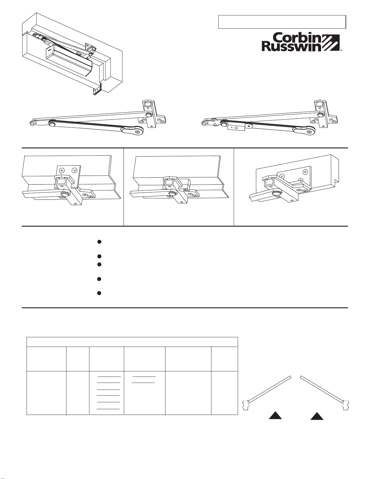
Interior Exterior
In
Swing
Exterior
Out
Swing
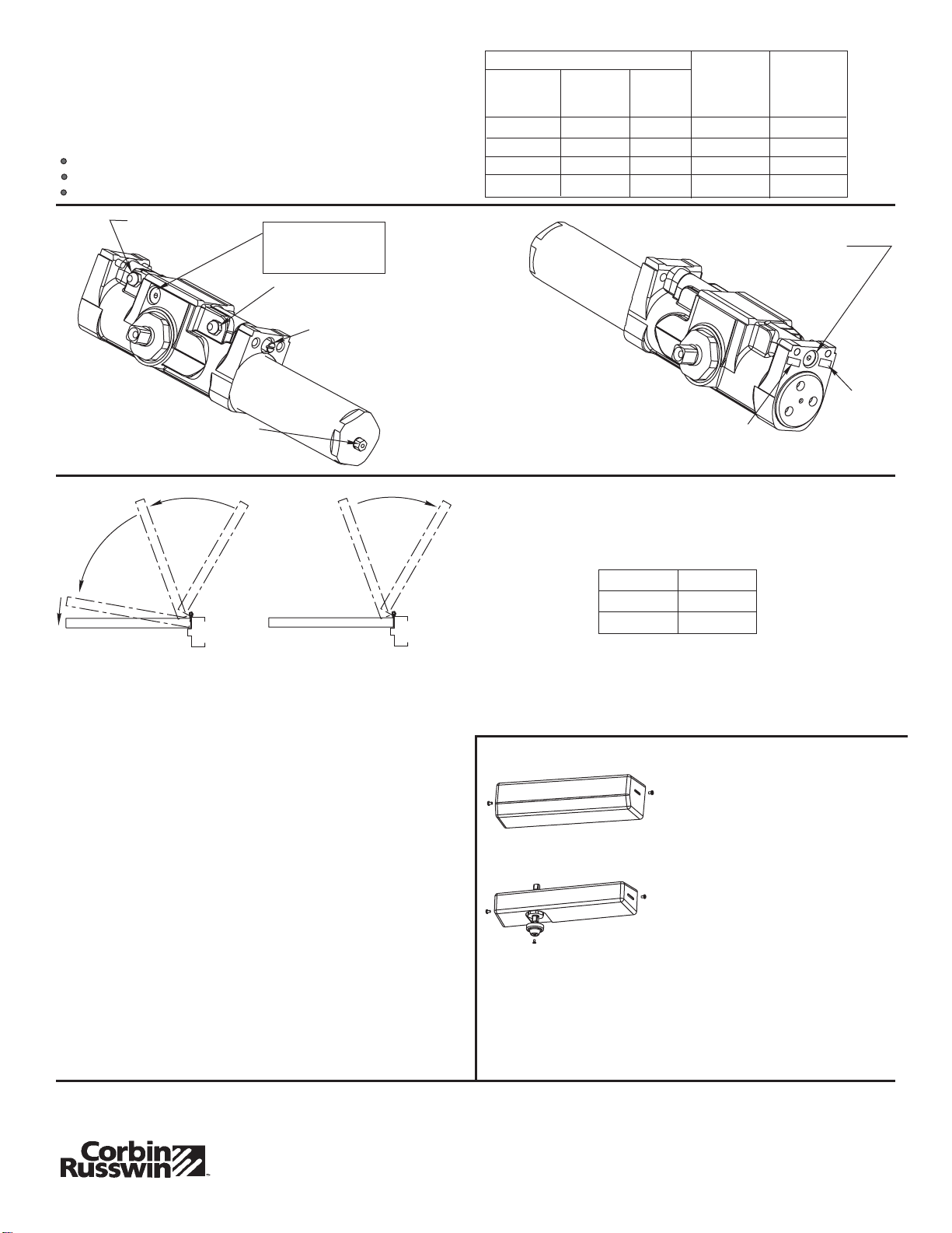
LATCHING
SPEED
VALVE
BACKCHECK
INTENSITY VALVE
BACKCHECK
LOCATION VALVE
OPTION M71
DELAYED
ACTION VALVE
CLOSING
SPEED VALVE
SPRING POWER ADJUSTER
(5/16 WRENCH or SOCKET)"
Size of Door No. of Full
(360°) Turns
Clockwise
of Power
Adjuster
(Approx.)
Equivalent
Closer Size
DC6200 SPRING POWER ADJUSTMENT CHART
2 4 (712)
2 6 (764)
3 0 (915)
3 6 (1067)
'"
'"
'"
'"
4
8
12
16
2
3
4
5
2 6 (764)
3 0 (915)
'"
'"
2 6 (764)
3 0 (915)
3 6 (1067)
4 0 (1219)
'"
'"
'"
'"
Spring Power Adjustment
DC6400 Half Size Adjustment as Desired
DC6200 Size 1 thru 6 Adjustment See Chart
All DC6200 closers are factory set at an approximate
Adjust closer as necessary for door size using this chart.
Readjustment may be required to suit prevailing conditions.
Size 3.
Locate spring power adjuster from Illustration below
Backcheck Location Valve
Valve is closed, as shipped, from factory. To increase the
degree of door opening where backcheck takes effect, turn
valve counter-clockwise.
Backcheck Intensity Valve
Turn valve COUNTER- CLOCKWISE to reduce backcheck
or CLOCKWISE to increase backcheck. (Backcheck should
be set to give a soft cushioning action, not a sudden stop).
CLOSED
OCCURS AT
OPEN
65°-70°
95°-100°
VALVE
Degrees shown are approximate
(FLAT TIP SCREWDRIVER
W/ 5 (127mm) Min. Shaft Length)
"
Latching Speed Valve
After closing speed has been obtained, turn latching speed valve
CLOCKWISE to SLOW latching or COUNTER-CLOCKWISE to
SPEED latching for last 2 to 5 of door travel.
NOTE: Set combination of CLOSING and LATCHING speeds to
between 3 and 7 seconds Use of door by handicapped,
elderly or small children, may require even greater
closing time.
""
Closing Speed Valve
To adjust speed of door closing from fully open to a position
2 to 5” from closed, turn Closing Speed Valve CLOCKWISE
to SLOW closing, COUNTER-CLOCKWISE to SPEED
closing.
"
Delayed Action Valve
Turn valve CLOCKWISE to SLOW closing, COUNTER-
CLOCKWISE to SPEED closing. Delayed action may be
adjusted from 20 seconds to 90 seconds, depending on
degree of door swing. Delay occurs at the beginning of the
door closing cycle from fully open down to 70°, where the
closing speed valve then begins its control.
Latch
C
l
o
s
i
n
g
S
p
e
e
d
B
a
c
k
c
h
e
c
k
D
e
l
a
y
e
d
A
c
t
i
o
n
Option
M-71
Full Cover
(Standard)
Slim Cover
(Option M76)
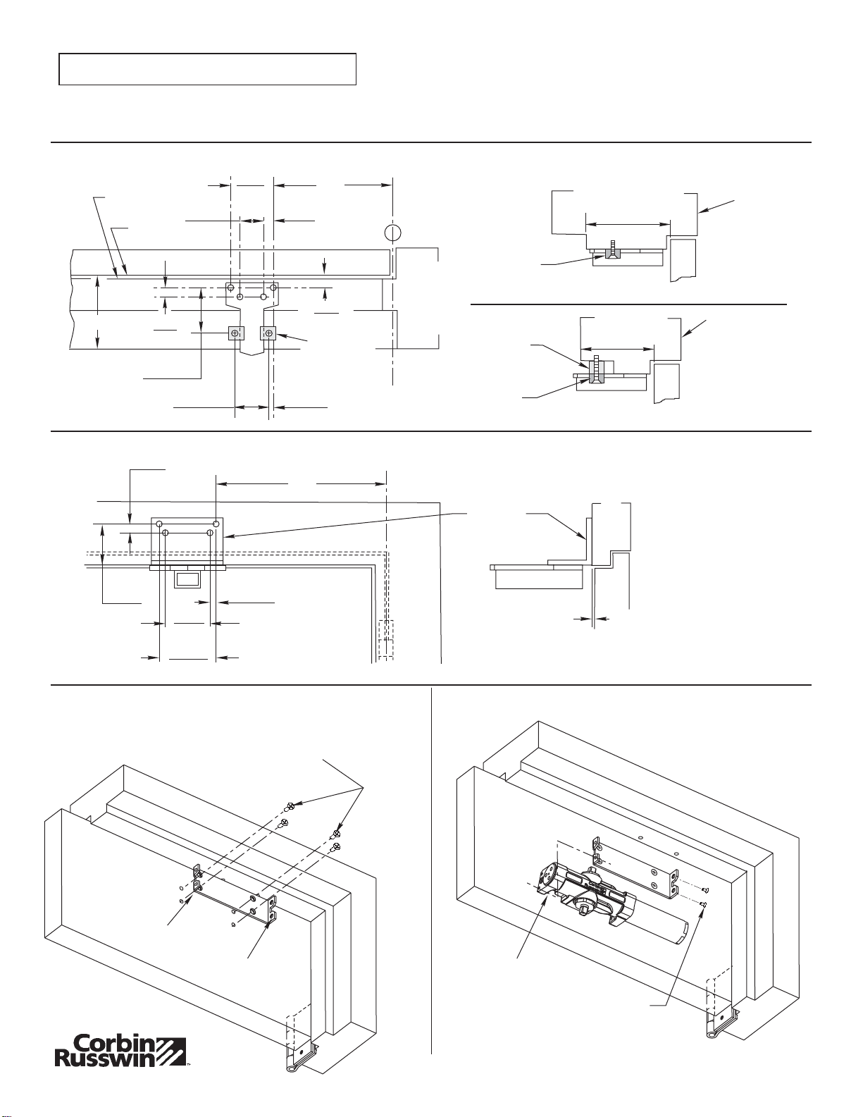
Slip cover over closer. Hold tightly
against closer mounting surface.
Secure on each side with 6-32 x 1/4
PBHMS screws. "
Slim Cover Option M76 only
Position spindle cap over unused
spindle and secure with
10-32 x 3/8 PTHMS screw.
(3/32 Allen Wrench Provided)
(3/32 Allen Wrench Provided)
(3/32 Allen Wrench Provided)
(3/32 Allen Wrench Provided)
Installing Cover
Power
Size
Stamp
Date Stamp