ENGLISH 6
4 FITTING
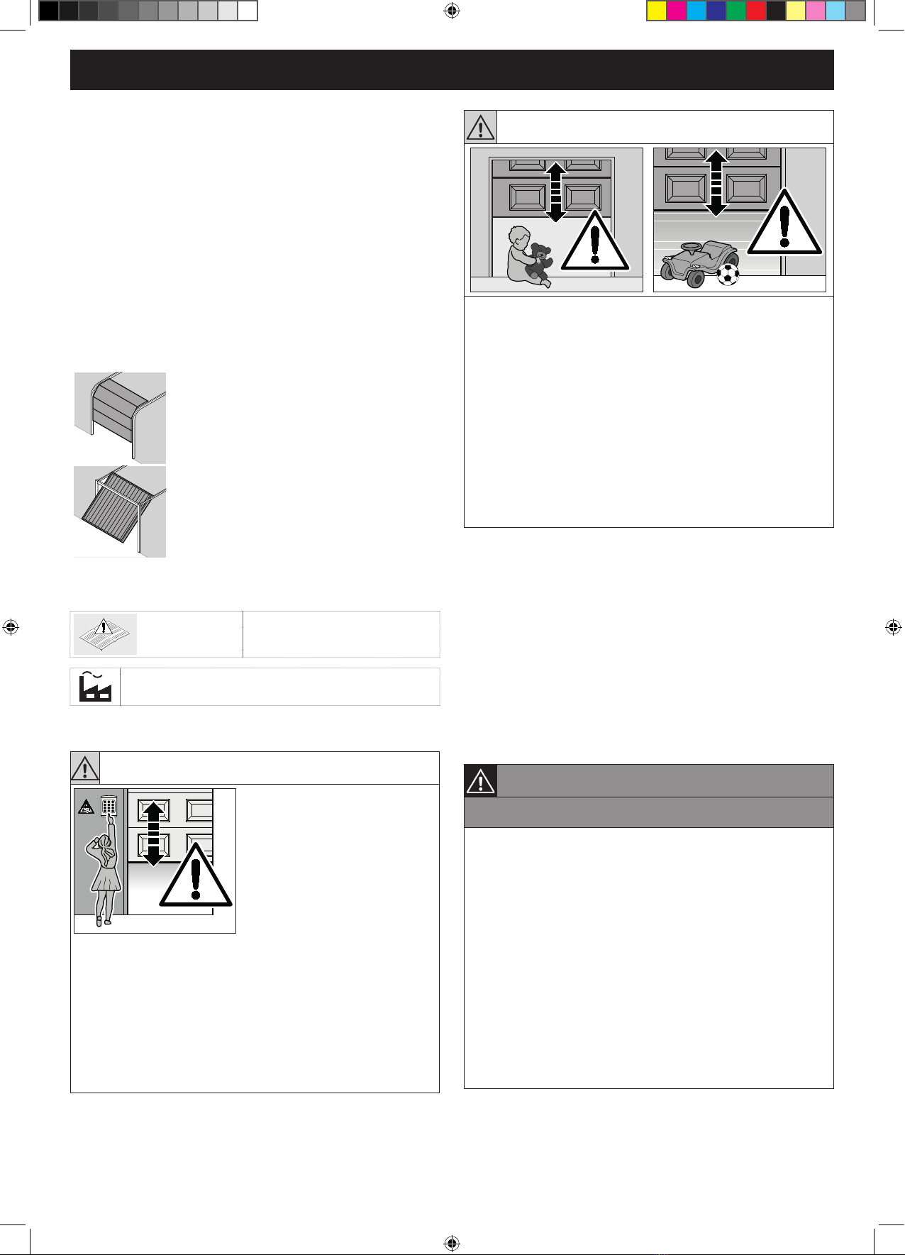
4.1 Inspect door / door system
Thedoormustbeinaawlessmechanicalcondition,aswell
as correctly balanced, so that it can be easily operated by hand
(EN 12604).
►Lift the door by approx. one metre and let it go. The door
should stay in this position and neither move downward nor
upward. If the door does move in either direction, there is
a danger that the compensating springs / weights are not
properly adjusted or are defective. In this case, increased
wear and malfunctioning of the door system can be expected.
►Check whether the door can be opened and closed correctly.
►The mechanical locking devices of the door that are not
needed with a garage door operator must be put out of
commission. This especially includes the locking mechanisms
of the door lock.
►Thettermustcheckthatthettingmaterialssuppliedare
suitableforthepurposeandtheintendedttinglocation.
4.2 Clearance required
▪The clearance between the highest point of door travel and
the ceiling (even when opening the door) must be at least
30 mm. See Figures 1.1a and 1.2b.
▪If the clearance is smaller, the operator can also be mounted
behind the opened door if enough space is available. In this
case,anextendedttingbracket(orderedseparately)must
be used.
▪The garage door operator can be arranged up to max.
500 mm off-centre.
▪ Theelectricaloutletshouldbettedapprox.500mmfromthe
operator head.
Check these dimensions!
4.3 Preparing the door
WARNING!
Danger to life from the pull rope!
A running rope may lead to strangulation.
►Removetheropewhilettingtheoperator(seeFigure1.2a).
►Completely disassemble the mechanical door locking on the
sectionaldoor.Seegure1.3aonpage 21.
►Withanoff-centrereinforcementproleonthesectionaldoor,
tthelinkbracketonthenearestreinforcementproletothe
leftorright.Seegure1.5aonpage 22.
►For sectional doors with centre door locking, arrange the lintel
jointandlinkbracketmax.50cmoff-centre.Seegure1.6a
on page 23.
►Render the mechanical door locking on the up-and-over door
inoperable. For door models not covered here, block the
catches on site. See Figures 1.3b/1.4b/1.5b on page 24.
►In a deviation from the illustrated section, attach the lintel
ceiling console and link bracket max. 50 cm off-centre for
up-and-over doors with ornamental iron door handles. See
gure1.6bonpage 25.
►ForN80doorswithtimberinll,thebottomholesonthelintel
jointmustbeusedfortting.Seegure1.7bonpage 25.
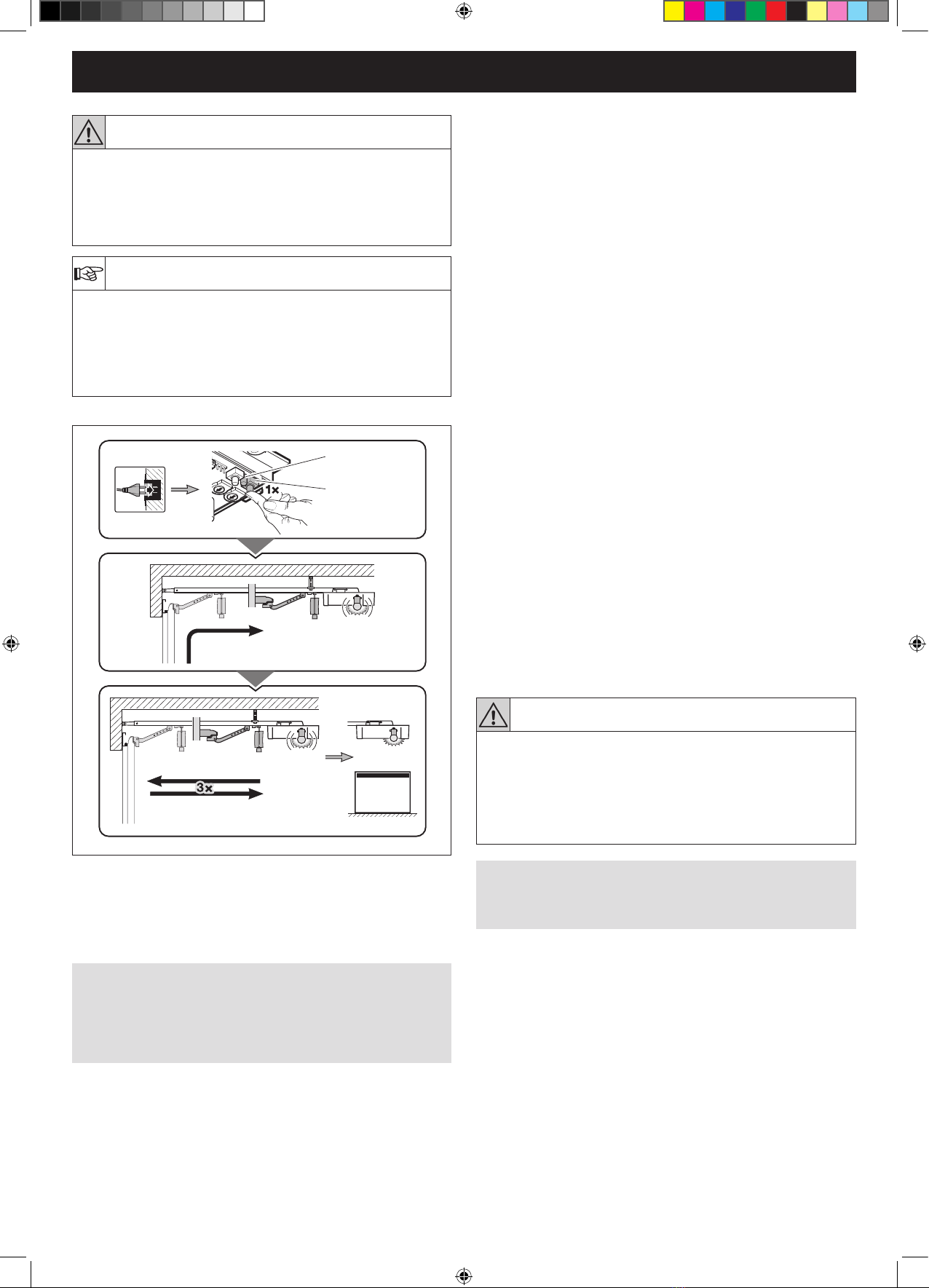
4.4 Fitting the boom
WARNING!
Unsuitable xing material
Useofunsuitablexingmaterialmaymeanthattheoperatoris
insecurely attached and could come loose.
►Thettermustcheckthesuitabilityoftheprovidedxing
material(plugs)foruseintheintendedttinglocation.
►Onlyusetheprovidedxingmaterials(plugs)inconcrete
≥B15(seeFigures1.6a/1.8b/2.4).
ATTENTION!
▪Before the boom is fi tted on the lintel and under the ceiling,
shift the slide carriage approx. 20 cm towards the middle of
the boom. This is no longer possible once the end stops and
operator have been fi tted.
▪Only use the booms recommended by us for the garage door
operators – depending on the respective application!
▪Drilling dust and chippings can lead to malfunctions.
Cover the operator during drilling work..
Note
A second suspension is recommended with divided rails
(availableunderaccessories)(seegure2.5onpage 27).
4.5 Boom operating modes
4.5.1 Manual operation
The slide carriage is disengaged from the belt lock to enable the
door to be moved by hand. For disengaging the slide carriage:
Pull on the cord of the mechanical release.
Seegure4onpage 30.
4.5.2 Automated operation
The belt lock is engaged in the slide carriage to enable the door
to be moved with the operator. For preparing the slide carriage
for engaging:
• Pressthegreenknob.Seegure6onpage 30
• Move the belt in the direction of the slide carriage until the belt
lock engages.
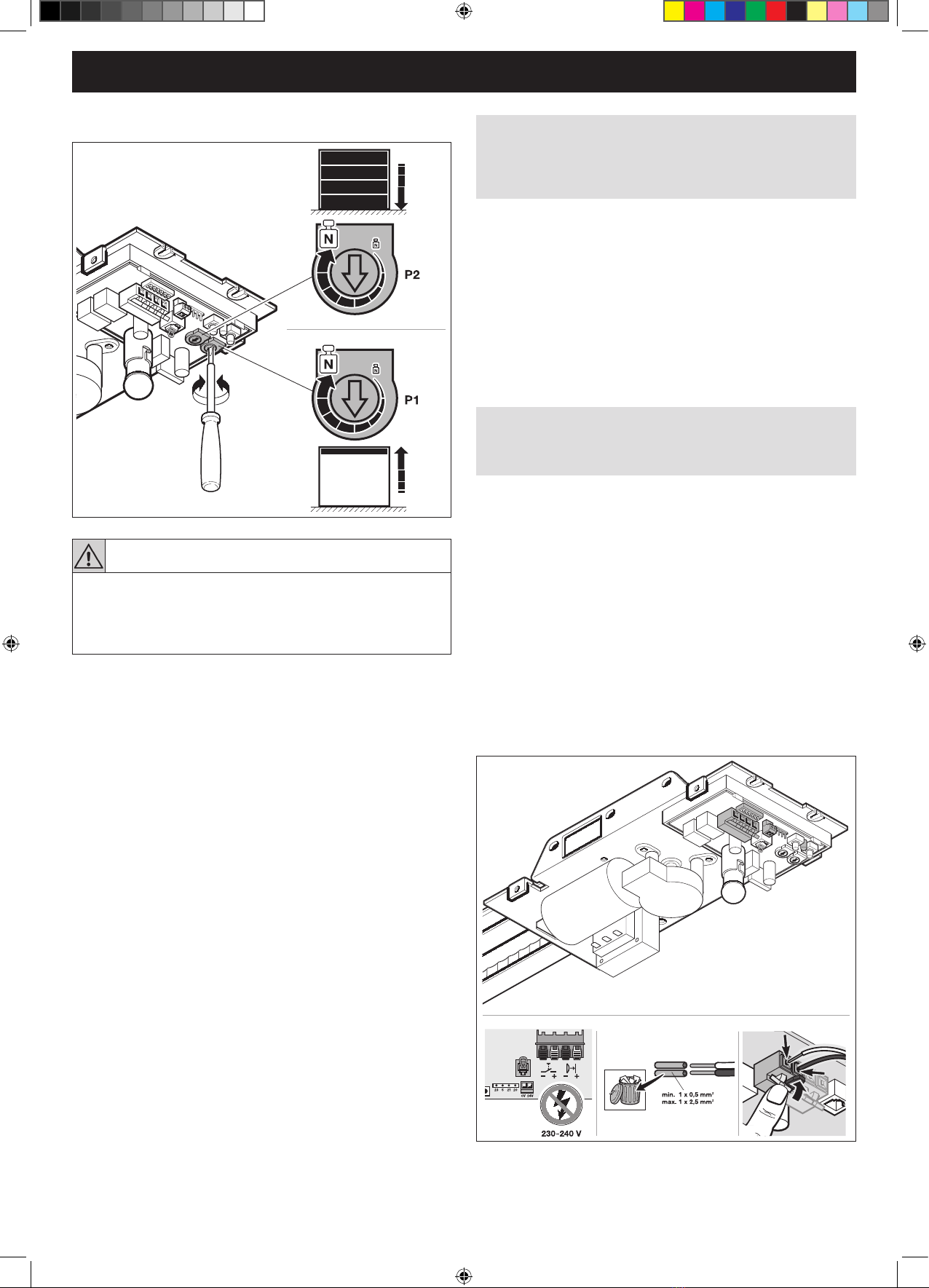
4.6 Emergency release
WARNING!
Danger of injury by fast-closing door!
If the cord knob is actuated while the door is open, there is a
danger that the door will close rapidly if the springs are weak,
broken or defective, or if the counterbalance is inadequate.
►Only pull the cord knob when the door is closed!
An emergency release is necessary for garages without a
second entrance that prevents the possibility of being locked
out; this must be ordered separately.
►Check the emergency release monthly for proper function.
EBA GA103_4ddoors_GBR, Rev. 1.0, 25.04.2014.indb 6 5/26/2014 9:53:22 AM