4EVAC 4E-FM User manual

Hacousto Holland bv
Industrieweg 87
2651BC Berkel & Rodenrijs
4E-FM installation and user guide
Author:
DD
Page 1of 12
SUMMARY
This document includes both the installation and user guides of the 4E-FM, the fireman microphone station
for the Compact 500 Voice Evacuation System. It explains how the 4E-FM should be installed and
configured. The installation instructions are addressed to trained technical personnel, such as installers,
service technicians and commissioning engineers. User instructions explain how to operate the 4E-FM and
how to interpret indications by the end users as well as technical personnel, such as service technicians.
REVISION AND APPROVAL
Rev.
Date
Nature of Changes
Approved By
01
31-07-2017
Original draft
DD
02
05-06-2020
Corrections
TvdH

Hacousto Holland bv
Industrieweg 87
2651BC Berkel & Rodenrijs
4E-FM installation and user guide
Author:
DD
Page 2of 12
Table of Contents
1. What is the 4E-FM?................................................................................................................................................................. 3
2. Where do I start?..................................................................................................................................................................... 3
3. Configuration settings ........................................................................................................................................................... 4
4. Hardware installation and settings.................................................................................................................................... 4
L-Net .................................................................................................................................................................................. 4
4.1.1. Network ports................................................................................................................................................... 5
4.1.2. Redundant link ................................................................................................................................................. 5
4.1.3. Network cabling............................................................................................................................................... 6
Device ID............................................................................................................................................................................7
5. Front Panel................................................................................................................................................................................. 8
LED indicators ................................................................................................................................................................. 8
5.1.1. POWER................................................................................................................................................................ 8
5.1.2. 8
5.1.3. EVAC .................................................................................................................................................................... 9
5.1.4. FAULT .................................................................................................................................................................. 9
5.1.5. BUSY – blue LED .............................................................................................................................................. 9
Manual controls ............................................................................................................................................................10
5.2.1. PTT.......................................................................................................................................................................10
6. Technical specifications........................................................................................................................................................ 11

Hacousto Holland bv
Industrieweg 87
2651BC Berkel & Rodenrijs
4E-FM installation and user guide
Author:
DD
Page 3of 12
Thank you for choosing 4EVAC as your Voice Evacuation System solution.
4EVAC Compact 500 is all-in-one Voice Evacuation System box. The box contains a completely integrated
Voice Evacuation System, capable of both standalone and network operation. 4EVAC Compact 500 is
certified in accordance with EN54-16 and EN54-4, which are harmonized standards under Construction
Products Regulation, mandatory in the European Union.
1. What is the 4E-FM?
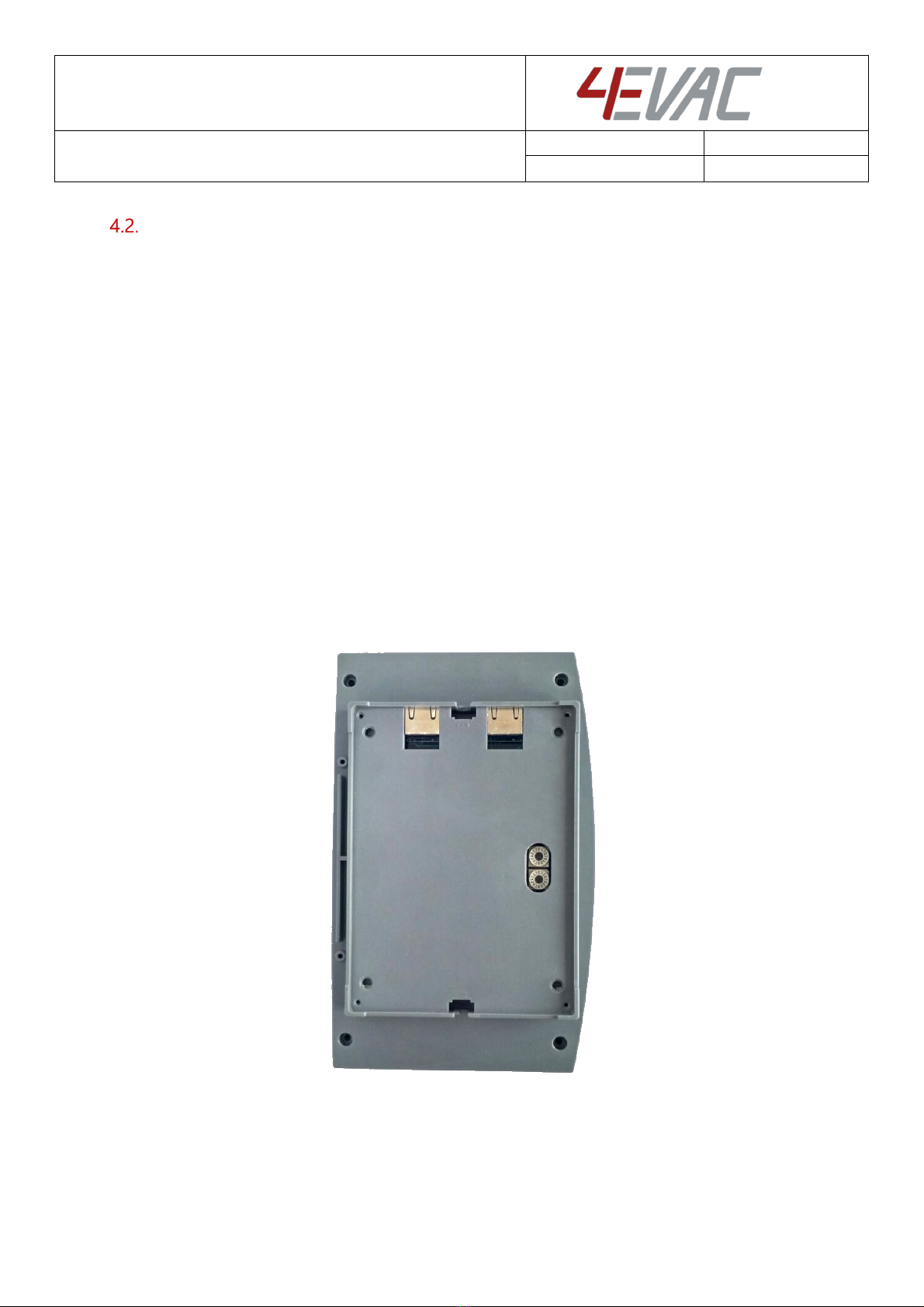
4E-FM is a desktop or wall mounted emergency microphone
station with high priority and fault surveillance.
It can address any zone or set of zones in the entire system,
including all call, for highest priority voice emergency. The 4E-FM
includes a handheld microphone and monitored PTT TALK
button..
The 4E-FM is connected to the L-Net interface of the Compact 500
main unit and may be daisy-chained with more L-Net devices. 4E-
FM is dedicated to emergency purposes and can be used by fire
brigades, rescue teams and authorized security personnel. As an emergency microphone compliant with
EN54-16, 4E-CMP features built-in surveillance of the microphone transducer, PTT button and network link
monitoring. It also offers a redundant L-Net connection for installations with special security requirements.
2. Where do I start?
First, make sure that you are officially allowed to access the hardware of Compact 500 system devices. This
is usually the case if:
you are an authorized representative of 4EVAC;
you have been trained by 4EVAC or one of its authorized representatives for installation, service
and commissioning of Compact 500 Voice Evacuation System.
Unauthorized hardware and/or software modifications are against the law and outside of the
manufacturer’s responsibility. If you have doubts about your status and access level permissions, please
contact the 4EVAC main office.
Important note: Access level 3 explanation
Opening the device housing or tampering with network cabling is
restricted. This gives access to all interfaces, internal system
connections and sensitive hardware settings that are of high
importance to system operation mode, hardware reliability and safety
(Access Level 3 according to EN54-16, Annex A). This access level (and
higher) is strictly protected by the manufacturer and reserved only for
service personnel which is trained, approved and officially certified by
the manufacturer. Any actions carried out in Access Level 3 without the
manufacturer’s explicit approval may lead to incorrect settings or
hardware damage, causing serious system malfunction, and therefore
are strictly prohibited and void manufacturer’s warranty.

Hacousto Holland bv
Industrieweg 87
2651BC Berkel & Rodenrijs
4E-FM installation and user guide
Author:
DD
Page 4of 12
3. Configuration settings
Settings for the 4E-FM are included in the configuration file located on the micro SD memory card installed
in the Compact 500 main unit.
The configuration file includes user-defined settings, such as:
-Pre-defined set of zones for PTT button (unlimited)
-microphone volume level,
-device priority.
The configuration file should be prepared in the C500 Manager. C500 Manager is GUI software running on
Windows OS. More information about the C500 Manager can be found in the software manual “C500
Manager guide”.
NOTE: Please make sure that the configuration file is prepared with the version of the C500 Manager
compatible with firmware of Compact 500.
The installation file of the latest 4EVAC Manager and the manual are available at our website
www.4EVAC.com
4. Hardware installation and settings
L-Net
4E-FM is a remote station connected to the L-Net port of the C500 main unit. Multiple 4E-FM stations may
be used in the same L-Net, with following limitations:
A maximum of 8 stations per L-Net port
A maximum of 16 stations per single C500 main unit (total sum of all 3 L-net ports)
The microphone station may be also daisy-chained together with other L-Net devices
Compact 500 L-Net (local network)

Hacousto Holland bv
Industrieweg 87
2651BC Berkel & Rodenrijs
4E-FM installation and user guide
Author:
DD
Page 5of 12
4.1.1. Network ports
4E-FM offers 2 L-Net ports (RJ-45) for network connections to the C500 main unit and distributed parts of
the 4EVAC Voice Evacuation System. Both L-Net ports are equal, therefore there is no difference which port
is connected to which side of L-Net daisy-chain.
L-Net ports on the back side of 4E-FM
4.1.2. Redundant link
If you need to make a redundant L-Net connection to the Compact 500 main unit, connect both L-Net
ports of the device to two L-Net ports on the C500 main unit. You can choose any L-Net port on the C500
main unit. This creates a double daisy-chain of the redundant A/B power and data link to the device and
ensures fail-safe networking in case of single cable or port failure.
Both spurs of the redundant A/B link may be populated with other L-Net devices.
NOTE: The device is equipped with a power link jumper, which, by default, is in CLOSED position (pass-
through L-Net power bus over daisy-chain). In order to create a redundant link, the jumper must be moved
to the OPEN position. The device will be then immune to a single port short-circuit of the power bus.
Location of power link jumper

Hacousto Holland bv
Industrieweg 87
2651BC Berkel & Rodenrijs
4E-FM installation and user guide
Author:
DD
Page 6of 12
4.1.3. Network cabling
4EVAC network features a full duplex RS-422 data link and 24V DC power to remote devices.
If you’re building a distributed system using the 4EVAC network, you should make physical links between
devices using the right cables. The cabling should meet the following requirements:
1. Crossover twisted-pair cable (compatible with Ethernet crossover)
2. CAT5e or higher for maximum distance of 250m.
3. Non-CAT / lower than CAT5e: 250m not guaranteed.
4. Shield required (at least FTP)
NOTE: If you use a straight cable, the device will power up but the Tx/Rx data terminals will not be properly
connected. This will result in a communication fault between L-Net device and C500 main unit. The L-Net
device will not be able to initialize, and thus will remain in its boot-sequence, not operational.
Caution! Use only crossover cables and keep the correct pinout! Connecting power pins to data pins will
damage the network port.
pin number pin number
GND shield shield GND
RX+ 1 1 RX+
RX- 2 2 RX-
TX+ 3 3 TX+
power + 4 4 power +
power - 5 5 power -
TX- 6 6 TX-
power + 7 7 power +
power - 8 8 power -
pin number pin number
GND shield shield GND
RX+ 1 1 RX+
RX- 2 2 RX-
TX+ 3 3 TX+
power + 4 4 power +
power - 5 5 power -
TX- 6 6 TX-
power + 7 7 power +
power - 8 8 power -
xover type A cable
xover type B cable

Hacousto Holland bv
Industrieweg 87
2651BC Berkel & Rodenrijs
4E-FM installation and user guide
Author:
DD
Page 7of 12
Device ID
The microphone station needs an ID setting in order to be properly recognized in the network and operate.
If the device ID is duplicated or set to a wrong value, the device will not receive the correct configuration
settings from the master Compact 500 main unit. In this case the remote station will be stuck in its boot
sequence and remain non-operational.
The device ID is set by means of two rotary switches, which define the two-digit hexadecimal value of the
ID.
In order to check or set the Device ID, you must access the rotary switches on the back side of the unit:
1. Remove the steel plate covering the back of the station
2. Identify the high-significant and low-significant rotary switches. The Device ID is a combination [HI
LO] of those two digits.
3. Make sure the ID value exists in your configuration settings, relates to the right device type and is
not duplicated to another device. Allowed values: 01-FE
4. Set the Device ID value according to the configuration settings of the Compact 500 system.
5. Plug-in the L-Net cable connecting the station with the C500 main unit.
6. Observe the boot sequence, after which the unit should automatically enter its normal operating
state.
7. Assemble the back plate (and optionally the rubber feet).
4E-FM bottom view: Device ID setting
HI
LO

Hacousto Holland bv
Industrieweg 87
2651BC Berkel & Rodenrijs
4E-FM installation and user guide
Author:
DD
Page 8of 12
5. Front Panel
4E-FM front panel
Important note: Access level 2 explanation
Opening the front cover of the 4E-FM gives you physical access to the restricted area at access level 2 with
high priority manual control. Using it will trigger EVAC mode and will result in the voice alarm state in the
building. Control at access level 2 is strictly dedicated for emergency services, fire brigades, rescue teams
and authorized building security personnel. 4E-FM should never be used for general purpose paging by
unauthorized persons.
If you have doubts about the access level and your authorization to use the emergency microphone station,
then you’re probably not authorized to use it.
LED indicators
5.1.1. POWER
5.1.2.
Indicates the operating status of this station.
Continuous: device is powered and ready
Blinking fast: station is booting or not operational
oBoot sequence
OFF
Blink slow
Blink double
Blink fast
continuous
LED indication time chart

Hacousto Holland bv
Industrieweg 87
2651BC Berkel & Rodenrijs
4E-FM installation and user guide
Author:
DD
Page 9of 12
oNo communication with the C500 main unit
oWrong Device ID
5.1.3. EVAC
Indicates that the system is in Voice Alarm, where at least one zone in the system is occupied by an
emergency audio signal, i.e. a pre-recorded EVAC MESSAGE or LIVE EVAC, when a fireman microphone is
being used.
Continuous: EVAC state
5.1.4. FAULT
Indicates that the system is in its FAULT state (general fault indicator), where at least one device in the
system is reporting a fault.
Continuous: when a local station fault is detected
oMicrophone short or open circuit
oPTT button short or open circuit
oNetwork link fault
Blinking slow: when the local station is healthy and at least one remote device is reporting a fault
state
5.1.5. BUSY – blue LED
Zone busy LED. Indicates current status of the pre-defined set of zones addressed by this station.
Blinking fast: the set of zones is occupied by an audio signal, but is in SILENCE mode (triggered by
SILENCE input or manual SILENCE button)
Blinking slow: indicates that the set of zones are currently transmitting an audio signal (except
BGM) from another device.
Blinking double: indicates that the set of zones is currently transmitting an audio signal from this
microphone station.
NOTE: BGM transmission is not indicated.

Hacousto Holland bv
Industrieweg 87
2651BC Berkel & Rodenrijs
4E-FM installation and user guide
Author:
DD
Page 10 of 12
Manual controls
5.2.1. PTT
This button starts EVAC voice transmission to pre-defined zones. When activated, the entire Compact 500
system is in EVAC mode.

Hacousto Holland bv
Industrieweg 87
2651BC Berkel & Rodenrijs
4E-FM installation and user guide
Author:
DD
Page 11 of 12
6. Technical specifications
4E-FM
Number of zones
255 (global access, no restrictions)
Controls and indications
PTT button, POWER/FAULT/EVAC/BUSY LED indicators
Microphone
Integrated commercial purpose mic
Type
MEMS transducer, hand-held
Power consumption
24V (L-Net)
max. 50mA
Audio
Frequency response
100 Hz – 12 kHz
Digital audio format
24 kHz sampling, ADPCM compressed
Audio processing
Fixed BP filter, fixed dynamics compression
Local network interface
Architecture
Master-slave, up to 16 slave devices per C500 main unit
Connection
RJ-45, powered daisy chain, digital audio & control data, redundant
Cabling
X-over FTP CAT5e (or higher)
Current rating via single link
max. 500 mA (up to 8 slave devices) via L-Net port,
Max. length of L-Net link
250 m
Mechanical
Dimensions HxWxL)
8 x 13 x 21 cm
Weight
380 g
Housing material
Steel / ABS
IP rating
IP 30
Mounting
Desktop wedge / wall-mounted (incl. wall bracket)
Operating conditions
Temperature
10–40°C
Relative humidity
max. 90% (non condensing)
Storage temperature
-40–70°C

Hacousto Holland bv
Industrieweg 87
2651BC Berkel & Rodenrijs
4E-FM installation and user guide
Author:
DD
Page 12 of 12
MADE IN THE NETHERLANDS
4EVAC is a trade name of:
Hacousto Holland bv
Industrieweg 87
2651BC Berkel & Rodenrijs
The Netherlands
www.4EVAC.com
This manual suits for next models
1
Table of contents
Other 4EVAC Microphone System manuals
Popular Microphone System manuals by other brands

Kistler
Kistler 9813B Series instruction manual

Better Music Builder
Better Music Builder VM-88 operating instructions

Audio Technica
Audio Technica ATW-A10 Installation and operation

thomann
thomann the t.bone freeU Twin HT user manual

Inter-m
Inter-m RM-88 Operation manual

Allison Transmission
Allison Transmission Motorhome Series Operator's manual