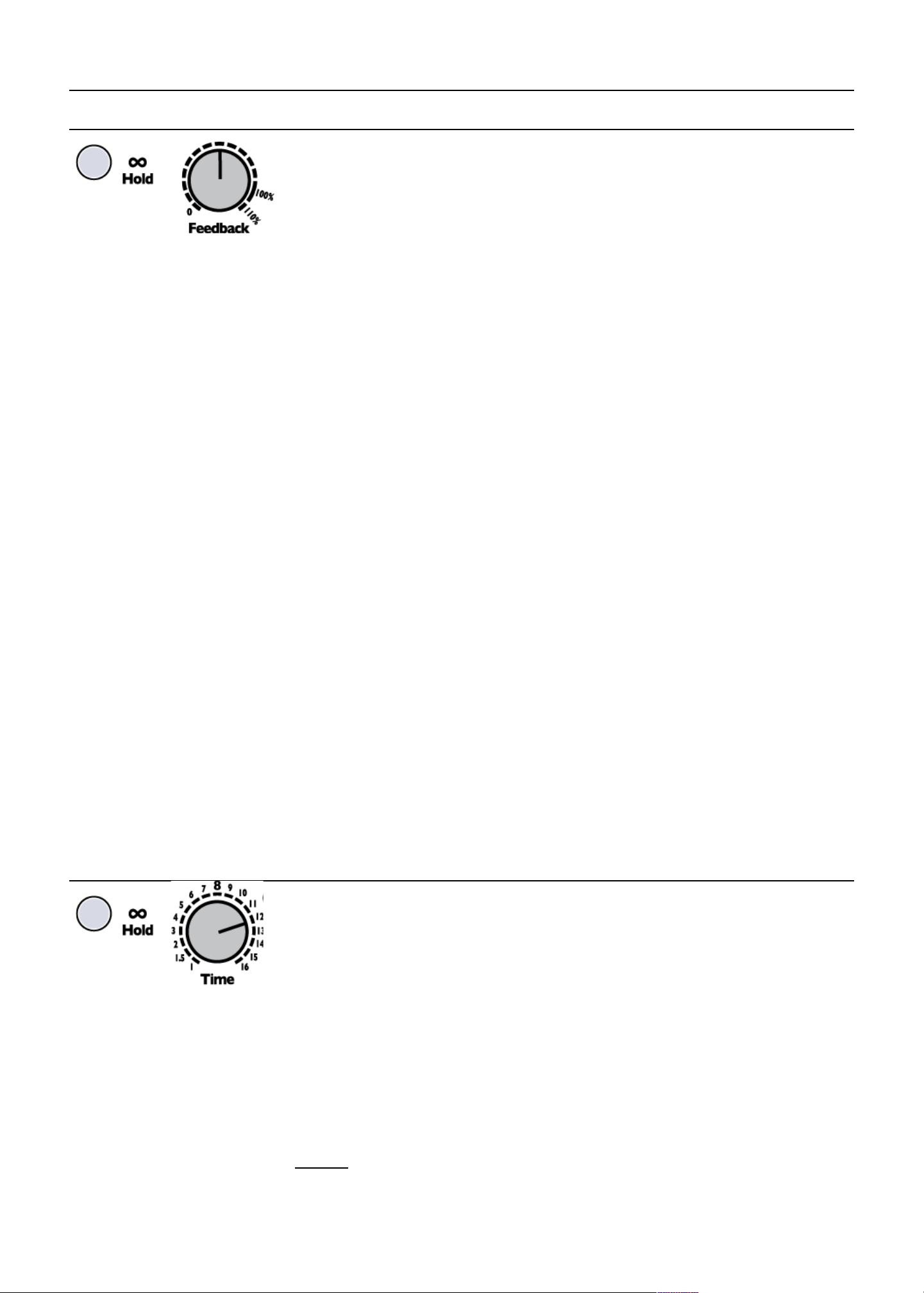
4ms Dual Looping Delay User manual

Dual Looping Delay
from 4ms Company
Eurorack Module User Manual 1.0b (201 -June-2)
For firmware version 4
The Dual Looping Delay (DLD), designed by 4ms Company and Gary Hall, is an advanced audio processor for
creative synthesis Not a tape or analog emulation, but a modern crystal-clear digital delay, the DLD combines
features of delay, looping, and sample-tight synchronization for powerful and dynamic sound capture and
modification The DLD is designed to integrate seamlessly with modular timebase and sequencing devices such as
the 4ms Quad Clock Distributor (QCD), etc
•Two channels, each with nearly 3 minutes maximum delay/loop time at 48kHz/16-bit (option for 24-bit)
•Extremely quiet, low noise, low jitter design
•Stereo, cascading, or dual independent mono use
•Delay and loop time is sync-able to a clock, or a division or multiplication of a clock
•Infinite Hold mode for looping and windowing
•Reverse feature for toggling direction of playback
•Feedback ranges from 0% to 110%
•1V/octave tracking for Resonant Delays (Karplus-Strong)
•Wet/Dry mix output, as well as dedicated Send/Return for feedback loop
•CV and trigger inputs for all major features

Basic features:
•Two independent delay/loop channels, synchronized to a common time base
•Almost 3 minutes of time per channel (2:54) in 16-bit mode, for a total of nearly 6 minutes
•48kHz/16-bit sampling rate, option available for 24-bit sampling (results in 88 seconds delay/loop time per channel)
•Extremely quiet, low-noise and low-jitter design
•Normaled connections of input and output for flexible use in mono, stereo, cascading, or parallel mode
•Tap tempo button and clock Ping input set the timing for one "beat"
•Delay/loop time set as a number of musical beats (or fractions of beats) using the Time knob, switch, and CV jack
•Sample-accurate master clock output for perfect synchronization
•Loop clock outputs for each channel
•Time switches change range of Time knob from 1/8th notes up to 32 bars
•Digital feedback, up to 110%
•Delay Level control, independent of dry/wet signal mix
•Infinite Hold mode disables recording and plays a loop
° Start and End points of loop can be modified in real-time for “scrubbing” or “windowing” effects
•Reverse mode plays memory contents backwards
•Resonant Delays (ala Karplus-Strong)
° External clock input can track an external VCO up to 2kHz, and multiply it up to 16kHz
° Time CV jack can respond at 1V/octave in Unquantized Time Mode
•Trigger inputs for toggling Infinite Hold and Reverse
•Send and Return on each channel for feedback with external modules
•CV jacks to control Time, Delay Feed (record level), and Feedback
•As new features are developed, firmware can be updated by playing an audio file into the DLD
° Open-source design allows the DLD to be a versatile platform for custom firmware
•System Settings Mode for fine-tuning parameters such as 1V/oct tracking response, and gate/trigger clock output
•Buffer can be cleared with a button press
•20HP Eurorack module
Controls and jacks:
Channels A and B are identical and separate, except for the common clock and audio normalizations
Controls
•Ping button: Tap a tempo to set the base clock = one beat
° Base time can also be set by an external clock
•Time knob per channel: sets the loop time in number of beats Ranges from 1 to 16
•Time switch per channel: modifies the Time knob setting
° Down = 1/8 notes Loop/delay time will be 1/8 to 16/8 = 2 beat
° Center = normal Loop/delay time will be 1 to 16 beat
° Up = +16 Loop/delay time will be 17 to 32 beat
•Feedback knob per channel: sets amount of signal read from memory to be written ahead in the future
•Delay Feed knob per channel: sets amount of input signal from the In jack to be written to memory
•Mix (Dry/Wet) knob per channel: cross-fades between signal on In jack (dry) and the signal read from memory (wet)
•Reverse button per channel: reverses the direction of memory read/write
° Reverse feature is toggled when the button is released (not when it is depressed)
•Infinite Hold button per channel: toggles between Delay and Loop mode
° Delay mode works like a traditional echo or looping delay by recording and playing continuously
° Loop mode disables writing, and plays a loop whose length is set by the Time parameter
° Hold is toggled when the button is released
Jacks:
•Two audio inputs per channel
° In (Main)
° Return (from external feedback loop)
•Two audio outputs per channel (A/B)
° Out (Dry/wet mix)
° Send (Delay signal only)
•Ping input (clock sync)
•Main Clock output (stable master clock, quantized to sample rate)
•Loop clock output per channel (loop/delay time of each channel)
•Three CV input jacks per channel
° Time (-5V to +5V)
° Feedback (0V to +5V)
° Delay Feed (0V to +5V) (can be re-assigned to control Mix)
° CV jacks respond into the low audio range
•Two trigger inputs per channel (A rising edge of at least 1 6V on either jack toggles the parameter)
° Reverse
° Hold
2

Getting started: basic patches
Two channel delay: Mono input, stereo output
In this patch, both delay channels will be used (Channel A and Channel
B) First, patch a signal into the In A jack, and take the outputs from
Out A and Out B The signal you feed into In A will automatically be
fed to In B (as long as you don't plug anything into the In B jack)
Set the knobs and switches as shown Patch audio into the In A jack,
perhaps a sequenced melody or a drum pattern Monitor the output on
Out A and Out B jacks If possible, pan the two outputs in stereo Or
you can have both outputs mix together into the Out A jack by
unplugging the Out B jack
One channel delay: Mono input, mono output
You might think to run a mono signal, you should patch in and out of
channel A However, this will actually use Channel A and B in parallel
(which is great fun, but can be confusing if you're expecting only one
channel to be active) The reason is that Channel A's input and output
normalize to Channel B, this is will actually
To use just one channel, use Channel B as shown on the left
Resonant Delay (ala Karplus-Strong effect)
Resonant Delays are delays with short delay time (in the audio
range) and enough feedback to create a resonant sound
somewhat like that of a plucked string
The DLD supports Resonant Delays You can tap a very fast
tempo and flip the Time switch to 1/8, or (even better) feed a
square wave VCO into the Ping jack The VCO should be in the
low or mid audio range, less than 2kHz (250-500Hz is ideal)
Feed a signal into the In jack: noise works well, so do triggers
(10V triggers will resonant more, 5V triggers are barely enough to
trigger the resonance) Use the Time switch and knob to set the
Pitch Feedback sets the resonance (which determines the
amplitude of the pitch), and Delay Feed effects the level and
resonance as well Make sure Infinite Hold is off
Playing Resonance with a keyboard or sequencer
Holding down Infinite Hold and turning the Time knob changes
the DLD channel into Unquantized Time Mode (see section
below for discussion) This feature is great in combination with
Resonant Delays First get a nice resonant delay sound
happening Then hold down the Infinite Hold button and turn the Time knob slowly You should hear the pitch of the
resonance change smoothly (not stepping through quantized pitches) Now plug a 1V/octave keyboard or sequencer output
into the Time CV jack Plug the velocity output (or an envelope output that's triggered by each step of the sequencer) into the
Feedback jack Turn down the Feedback knob so that the velocity/pressure or the envelope make the DLD create individual
“notes” You can also patch into Delay Feed to get a different effect Since there are two DLD channels, you can use it as a
duophonic melodic instrument!
3
Input
Signal
Output
(left
channel)
Output
(right channel)
If unpatched, right channel will
mix into Out A jack
Square Wave
VCO ~500Hz
Time knob and
switch set pitch
Feedback 50-100%
(sets Resonance)
Input Signal:
noise, triggers
(or anything)
Input
Signal
Output

Concepts
On the back page of this manual is a block diagram of the control and signal paths for one channel The metaphor is that
each DLD channel is a tape loop, with a separate read and write head, and the ability to move each heads to a new location
The tape is assumed to move at a constant speed (constant sample rate), but can be reversed in direction The magic ability
to change the length of the tape loop is also assumed in this metaphor (Infinite Hold mode)
Ping: Setting the beat
The DLD requires a base time, which is referred to as a “beat” in this manual Each channel can have a different delay or loop
time, but both channels' delay/loop time will be mathematically related to the length of one beat If you are familiar with other
4ms modules, you may be familiar with the concept of “Ping” In the DLD, the beat is the Ping
There are several ways to establish the beat:
•Tap the Ping button twice One beat will equal the time between your taps
•Patch an external clock into the Ping jack One beat will equal the time between the last two
pulses
•Just turn on the DLD and do nothing more! The DLD automatically boots up at around 150BPM
•There is a fourth way of setting the timing, which is by enabling Clock Bus support on your D D and using a Clock
Bus master such as the QCD to send the clock over the power distribution board. See the Clock Bus Jumper section.
The DLD's clock is extremely stable and jitter-free It's highly recommended to use the internal DLD clock (tap clock) if
possible, because it's quantized to the sample clock and has less jitter than most common commercially available clock
sources Using the DLD as a master clock will provide the tightest timing possible in a patch with the DLD However, if it's not
possible to use the DLD as a master clock, you can sync to an external clock by patching it into the Ping jack The DLD will
quantize the external clock to its own sample rate and output quantized clocks on the two Loop jacks If there is any jitter or
drift in the external clock, the DLD will track and follow these discontinuities, which can result in interesting (or noisy! artifacts)
Channels
There are two channels: A and B Each channel has a separate audio path, controls, and CV/trigger jacks The channels are
identical — except for the fact that the inputs and outputs automatically connect together if nothing is patched into Channel B
(see below) Both channels share a common time base, or beat, which is set by the Ping button or jack Each channel can
multiply, divide, or add to the base time by using the Time knob, switch, and CV Anytime the base time is changed (by
tapping the Ping button, or changing the external clock), both channels will instantly change tempo while maintaining the
same ratio to each other
Channel normalizations
The main In A jack feeds into the switch tab of the main In B jack Therefore, plugging into the In A jack will run
the audio signal to Channel B as well If you plug a cable into the In B jack, then the normalization will be
disabled The “-->B” graphic on the panel near the In A jack reminds you of this normalization.
Similarly, The switch tab of the Out B jack feeds into the signal tab of the Out A jack Therefore, if nothing is
plugged into the Out B jack, then the output from channel B will be mixed with the output of channel A and
appear on the Out A jack The “<--B” graphic on the panel near the Out A jack reminds you of this normalization.
To use the DLD as a two-channel delay in parallel, plug into the In A and Out A jacks Both delay channels will
operate in parallel, mixing together into the Out A jack
To use the DLD as a one channel delay, plug into the In B and Out B jacks Channel A will not be used Alternatively, patch
into In A and Out A, and patch a dummy cable into Out B to disable the normalization
To use the DLD as a two channel series (cascading) delay, plug into the In A jack, and patch from Out A to In B, and then
take the output from Out B Alternatively you can patch from Send A to In B or Return B See the Using Send and Return
discussion in the Applications section below
Time
The Time parameter sets the length of the loop, or amount of delay time This period of time is
relative to a beat, which is set by tapping the Ping button or patching an external clock into the Ping
jack
The Time knob, CV jack, and switch perform simple arithmetic on the beat time to produce a
delay/loop time
•Time Switch center (=): the Time knob directly sets the number of beats for the loop or delay time Example: if you
turn Time to “5”, the channel will make an echo (or loop) every 5 beats.
•Time Switch up (+16): 16 is added to the whatever the Time knob shows
Example: if the Time knob is pointing to 5, the channel's delay or loop time will be 5 + 16 = 21 beats.
•Time Switch down (1/8): the Time knob is divided by 8, making the delay/loop time 8 times as fast (eighth notes)
Example: Time knob is at 5, the channel will echo in 5/8th notes, or eight loops for every five beats.
Using CV will modify the Time knob's setting by multiplying or dividing the knob's value Positive CV makes the delay time
longer, negative CV makes it shorter
4

In math:
Time switch up: Delay time = ([Knob x CV] + 16) x beat time
Time switch center: Delay time = (Knob x CV) x beat time
Time switch up: Delay time = ([Knob x CV] / 8) x beat time
“Knob” ranges from 1 to 16
“CV” ranges from 1 to 16 if positive voltage is applied to the Time CV jack (0 to +5V)
“CV” ranges from 1 to 1/16 (0 0625) if negative voltage is applied to the Time CV jack (0 to -5V)
Note that with 0V on the CV jack (nothing plugged in), CV=1, so it has no effect on the knob's setting.
For example, tap a tempo of 0 5 second This makes one beat be ½ second (120BPM)
Set the Time knob to 8, and the Time switch to center If there is no CV plugged in, the delay time will be 8 beats, or 4
seconds
Now flip the Time switch down to “1/8”, the delay time will be eight 1/8th notes, or ½ second
Now turn the Time knob down to “2”, and the delay time will be two 1/8th notes or 0 125 seconds
Now flip the Time switch up to “+16” and the delay time will be 18 beats, or 9 seconds
Now apply some CV, the Time will get slower as you apply positive CV, and faster as you apply negative CV
Setting two channels to different delay loop periods that are multiples of the same clock can result in very interesting phasing
arrangements!
Loop start and stop points
When Infinite Hold is on, changing Time will change the loop start point in order to make the loop the new length If you hold
down the Reverse button while changing Time, you will change the loop end point You also can use this to change a loop
that's, for example, 4 beats long into one that's 5 beats long, in two different ways (adding a beat to the end, or to the
beginning) There are many creative possibilities to be explored with adding and subtracting from the beginning and/or end of
a loop One idea is to “inchworm” up and down memory If you want to move more quickly than an “inchworm”, try windowing:
see the section below on Windowing.
Delay Feed
Delay Feed is the amount of signal from the In jack that's recorded in memory You can think of it as “Record
Level” or “Input Level”, but there is one important detail to remember:
Delay Feed doesn't effect the Dry signal (which is what's present on the Out jack when the Mix knob is set to
Dry) It just effects how much signal is laid down or recorded This detail is intentional because when doing
sound-on-sound techniques, you can play a sound continuously in the Dry channel while modulating Delay
Feed to fade in portions of the signal onto the loop
The knob and CV jack are added together and have a maximum combined value of 100% Negative voltage on the CV jack is
ignored Note that in Inf Hold mode, Delay Feed has no effect since there is no recording
Feedback
Also known as “regeneration”, “echo amount”, and other names, feedback is a common feature on delay
effects Feedback is the amount of signal read from memory that's written back to memory in a different
location This new location will be read again in the future, and written back again at yet another location in
the future Take a look at the block diagram on the back page to see how Feedback fits into the signal flow
On the DLD, Feedback ranges from 0 to 110%
With no feedback (knob at 0), and you will hear one echo As you turn Feedback up, you will gradually hear
more and more echoes (the amount of time before the echoes go to silence will increase)
With Feedback at 100%, the signal read from memory is written back to memory unaltered Thus, the echoes will never fade
out — an infinite loop But if you input a signal on the In or Return jacks, they will add to the feedback signal, which can result
in the sound gradually getting louder and louder as sound is added but never reduced The knob's range has been modified
to create a large area which is exactly 100%
With Feedback at 110%, the signal read from memory is boosted before written This makes the echoes louder and louder
each time For short delay times, this is a well-known “blooming echo” effect used in various styles of music including Dub
Reggae
Note that in Infinite Hold mode, Feedback has no effect However, see the section below on “Windowing” for the special
usage of the Feedback knob and jack while holding down the Infinite Hold button
The knob and CV jack are added together, and are have a maximum combined value of 110% Negative voltage on the CV
jack is ignored If the knob is set to 0%, then applying a voltage of 5V or greater will cause a Feedback amount of exactly
100% This is to allow for easy CV control of accessing 100% Feedback (any voltage greater than 5V = 100%, if the knob is
set to 0)
Mix
Mix controls the blend between the Dry signal and the Wet signal on the Out jack It does not effect the Send
jack The Dry signal is taken directly from the In jack (and not the Return jack) before the Delay Feed
parameter has any effect See the block diagram on the back page of the manual.
Mix does not have a CV jack, but starting in firmware v4, there is an option to make the Delay Feed CV jack
control Mix instead (see System Settings section)
5

Infinite Hold
The DLD can operate as a delay/echo or it can play a loop While you can make the DLD play loops by setting
Feedback near or at 100%, each channel has the ability to immediately jump in and out of a special mode
called Infinite Hold mode by pressing a button or receiving a trigger
Pressing the Infinite Hold button toggles the state of Infinite Hold when the button is released The light on the button
indicates whether the mode is on or off
Normally (Infinite Hold off), the channel records audio and plays it back after the delay time has passed Every sound the
channel makes is continuously recorded into memory
When Infinite Hold is on, the channel stops recording and only plays what's already recorded in memory, cycling through a
loop The size of the loop is set by the Time parameter When you activate Infinite Hold mode, the DLD will start looping
what you just recorded. The loop is defined by start and end points in memory Wherever the DLD is reading from memory will
become the start of the loop, and where it was writing to memory will become the end of the loop You can get a sense of
where the read and write positions are by listening to the Wet and Dry signals, respectively—the Wet signal is what's being
read from memory, and the Dry signal is more or less what's being written to memory (especially if Delay Feed is up and
Feedback is down) So
What's the difference between turning on Infinite Hold versus setting Feedback to 100% and Delay Feed to 0%?
Since setting Feedback to 100% (or close to 100%) and Delay Feed to 0% creates an infinite loop, the DLD acts similarly to
how it does when Infinite Hold is on However, there are a few important differences:
When Infinite Hold is on, you can adjust the Time parameter from one setting to another, and then back to original setting
and it will sound exactly the same as it did originally This is not the case with Infinite Hold off and Feedback at 100%:
changing Time to a faster setting will actually record the new shorter echoes into memory Then when you turn back to the
original slower Time setting, the DLD will be reading the shorter echoes and will echo these echoes in a longer echo
Therefore, even though the Time setting is the same as it was originally, it will sound different! The reason is that with Infinite
Hold on, the DLD does not record anything, but with Infinite Hold off and Feedback at 100%, it records all the echoes
Another difference is that when Infinite Hold is on, the Feedback knob has a special function: windowing Hold down Infinite
Hold while turning Feedback to change the start and stop points of the loop (see Windowing section in this manual) There is
no windowing with Feedback at 100% and Delay Feed at 0%, but there is the ability to fade in new sounds (layers) by fading
up the Delay Feed knob, or by applying CV (perhaps an envelope?) to the Delay Feed CV jack Or you can create blank
spaces by turning Feedback down momentarily The loop is more dynamic and mutable, versus when Infinite Hold is on, the
loop is more static and immutable
Reverse
Reverse reverses the direction that memory is read and written
Pressing the Reverse button toggles Reverse on/off when the button is released If you turn a knob while Reverse
is held down, the Reverse action will be cancelled (this is because holding a button while turning a knob is reserved
for special features such as Windowing)
Applying a trigger on the Reverse jack will toggle Reverse on the rising edge of the trigger
Reverse has slightly different effects depending on if you are in Infinite Hold mode or not:
In normal mode (Infinite Hold off), toggling Reverse causes playback and record to reverse direction The read and write
positions are also swapped This means that any audio that's already been recorded will be played backwards, but any new
audio will be played forwards (since it's recorded backwards and played backwards, it comes out sounding forwards) Note
that when Time is very fast, Reverse will seem to have little effect because it only reverses what's already recorded (which
has a short duration when Time is fast) Note: In firmware version 4 and later, toggling Reverse crossfades between the old
and new directions, but in earlier firmware versions it can cause an audible click. Upgrade if you have this issue.
In Infinite Hold mode, toggling Reverse plays the loop backwards The loop start point (as indicated by the Loop clock output
jack) will become the moment that the loop is pressed So by reversing forward and backwards you can shift the loop's phase
relative to the master clock of the other channel's loop This is especially useful if you are using the Loop Out jacks to trigger
something else in your patch (such as an envelope and VCA)
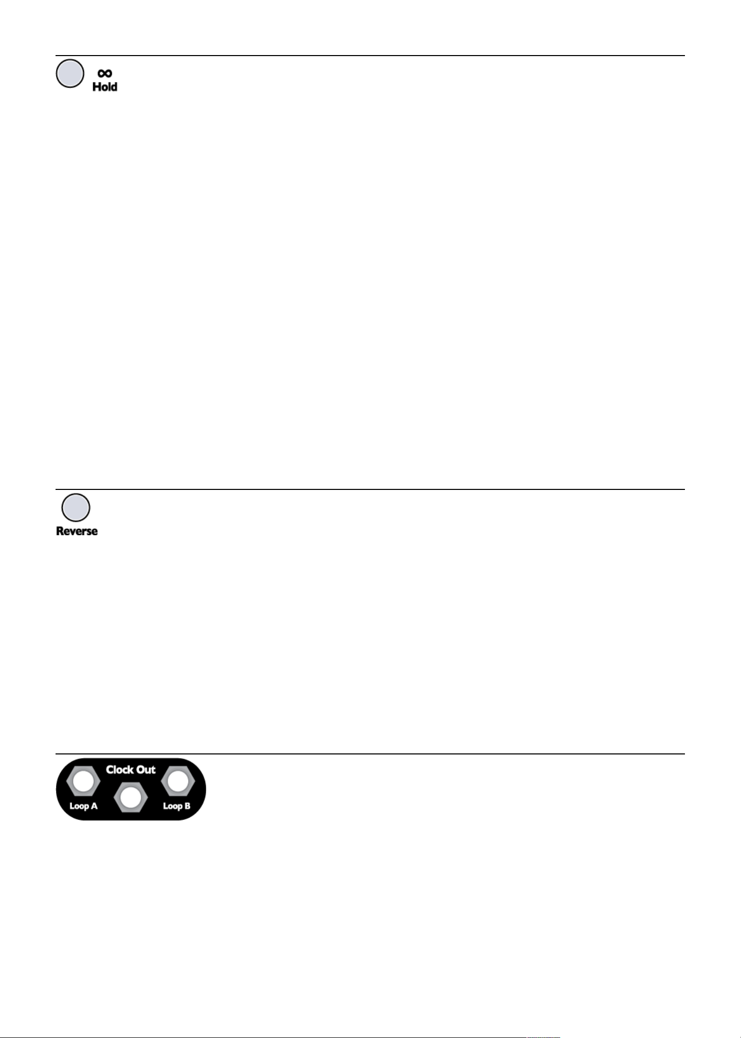
Clock Outputs
There are three clock output jacks:
•Loop A sends a clock that's in sync with the delay/loop time of channel A
•Loop B sends a clock that's in sync with the delay/loop time of channel B
•Clock Out (middle jack) sends a clock that's in sync with the master Ping clock
(whether you tapped in a tempo, or are using an external clock)
The red light near Time A shows the speed of the Loop A clock, and the blue light near Time B shows the speed of the Loop
B clock The jacks may output triggers, but the LEDs show equal on and off times, which is merely for aesthetic reasons
All the clock outputs are quantized to the sample-rate This insures they are jitter-free (assuming your external clock has a low
degree of jitter) The DLD clocks are some of the lowest jitter clocks available using Eurorack modules and should be used
whenever possible as a master clock
The high voltage of the clock outputs is 8V The pulse width is 22ms when in Trigger mode (default), as long as the clock
period allows for a 22ms pulse At fast clock speeds (audio rate), the jacks output square waves There is a System Setting
mode that allows you to change the clock outputs to gates rather than triggers (see System Settings Mode section)
In Infinite Hold mode, the clock goes high when the loop starts This can be used to trigger an envelope that VCA's the loop,
6

for example
Special Features
Windowing aka Scrolling aka Scrubbing
When Infinite Hold is on, the Feedback and Delay Feed parameters have no meaning
since they are effectively at 100% and 0% However, the Feedback knob and CV jack have
been given a special purpose when Infinite Hold is on: Windowing, also known as
scrolling or scrubbing
To use this feature, hold down the Infinite Hold button while turning Feedback. This will
cause the start and stop points of the loop to scroll forward or backwards, depending on
which way you turn Feedback The amount they scroll is determined by the amount you
turn Feedback: one full turn of the knob equals one loop length So if you have a 2 second loop, then turning Feedback from
0% to 100% will shift the loop forward by two seconds Turning Feedback from 100% to 50% will scroll the loop backwards by
one second
Note: Windowing only works when Infinite Hold mode is on.
Windowing Tutorial
Let's try it First get set up: Set Time so you have a loop length that's about a second or so Keep Feedback low to keep
things simple for now Play some sounds for 10-20 seconds and then turn on Infinite Hold to lock them in
Listen to your loop, pay attention to what sounds the loop starts with, and what sounds it plays right before it repeats These
are your loop start and stop points Now, we're going to change those start and stop points by Windowing:
1. Turn Feedback knob all the way up (the sound will not change)
2. Hold down Infinite Hold while you turn Feedback to 0%
You just shifted the loop backwards by one whole loop length Let it play for a bit as you listen to the new start and stop
points Hear it? The loop is the same length (same timing/tempo), but now it will be playing the sounds you recorded one
second earlier Play with this some more: Press and hold Infinite Hold again and turn Feedback back half a turn Hear how
the loop now starts in the middle? Remember that turning Feedback has no effect unless you're holding down Infinite Hold
This is critical for the next tip:
Tip #1: If you want to scroll more than one loop length, do this maneuver:
1. Turn Feedback to 100%
2. Depress Infinite Hold and turn Feedback to 0%
3. Release Infinite Hold
4. Repeat as needed (turn Feedback to 100%, then press Inf and turn Feedback back to 0, release Inf )
Tip #2: If you want to scroll back very far even more quickly than Tip #1, change the Time parameter to very long (perhaps flip
the time switch up to +16) Since turning Feedback + Infinite Hold scrolls by one loop size, making the loop size enormous
lets you scroll by enormous amounts with just one knob twist! You can scroll back a maximum of 2 minutes 54 seconds
Tip #3: Set Time to a very short period and window around a loop with CV for a sort of granular effect
Using CV with Windowing
The Feedback CV jack also allows you to window using external CV control To enable the CV jack, you must first manually
hold down Infinite Hold and turn Feedback, even just a small amount The Feedback CV jack will now control the window
If you turn the Feedback knob at any time without holding down Infinite Hold, the Feedback CV jack will no longer control
the window
Unquantized Time Mode and 1V/oct CV
Both channels of the DLD are always linked to a common time base Normally the Time
knob and CV are quantized to integer amounts (1-16), and simple fractions (1 – 1/16) This is
called Quantized Time Mode, and is the default mode It's possible to change to Unquantized
Time Mode, where the knob and CV provide continuous control of the Time parameter (not
quantized to integer or simple fractional amounts)
To change modes is simple:
•Unquantized Time Mode: Turn Time knob while holding down the Infinite Hold button
•Quantized Time Mode: Turn Time knob without holding down the Infinite Hold button
In Unquantized mode, the Time knob behaves as usual, except it does not snap to the whole numbers between 1 and 16 So
you can sweep a slowly changing tempo, or set an exact tempo in between two integer amounts To adjust the Time knob in
Unquantized mode, hold down the Infinite Hold button down while you turn the Time knob
The Time CV jack behaves differently in Unquantized mode: It responds over a 1V/octave curve for positive CV (5 octave
range) Applying up to +5V will multiply the Time knob's setting in an exponential curve relative to the voltage That is, for
every additional volt on the CV jack, the Time period will halve This is the opposite response as Quantized mode, where
additional voltage makes the period increase The 1V/octave response in Unquantized mode is very useful for resonant
delays
Note that if the Time switch is up, the 1V/oct response will be altered by the addition of the extra 16 bars. For a true 1V/oct
response, keep the Time switch centered or down. You also can adjust the exact 1V/oct tracking in System Settings.
7
+
+

Buffer Clear
When using the DLD with Feedback up and long loop times, it can take a while for the sound to die
out after the input signal is muted This is, of course, a very nice and useful effect, but if you find
yourself needing to clear the memory quickly you can do so by holding down Reverse and Infinite
Hold for two seconds The sound will cut out briefly while the memory is cleared and the lights will
flash Let go of the buttons and the buffer for that channel will be clear Each channel has its own
buffer, and can be cleared independently of the other
Why do I hear something I played a long time ago? Notes on the nature of Looping Delays
When Infinite Hold is off, the Wet signal (i e whatever's being output from the Send jack) is continuously recorded into
memory, going back for about three minutes (2:54 to be exact, which is the amount of each channel's memory) This means
that the results of every knob you twist and every bit of CV you input is being recorded into memory* Let's say you're playing
a melody into the DLD with a nice rhythmic echo If, for example, you change the Time parameter to make triplets for a
moment, then switch back to eighth notes, then maybe bring Feedback up to make a “bloom”, then pull down Delay Feed to
cut the audio out, etc all of this will be recorded into memory If you think in terms of the metaphor of a tape loop, then it's as
if your whole session is being recorded onto the loop
Normally you won't have to think about this: the DLD operates “as you think it should”, overwriting whatever it recorded 2:54
ago with what you're playing now But in some special circumstances, you can access this old memory: Windowing large
chunks in Infinite Hold Mode is the primary method whereby you might hear some sounds that were recorded onto the “tape
loop” several minutes ago This can be surprising! But it also can be very useful
Applications
Sound on Sound Looping #1
This is a great patch for long loops Set a long gentle clock speed (at least 1 second
between taps) The diagram on the left shows how to patch this for Channel B-- once you
master it, try patching both channels A and B and using the Out A mix jack for dual loops!
Turn Time B knob to 16 (or something slow) Turn Feedback B to 100% Turn Delay Feed
B to 0% Turn Mix to 50% (or to taste) Now run audio into In B Try running a melody or a
percussive sequence or an evolving drone, perhaps
Here's the trick: Patch a manual CV source into the Delay Feed B CV jack It can be a
Pressure Points, or an FSR pressure output, or perhaps an envelope output that's
triggered manually When you press on the Pressure Points or FSR, you will bring
up the Delay Feed parameter which causes audio to be recorded onto the loop
Since Feedback is at 100%, the loop is infinite and everything you lay down will
remain (but take care to keep your levels not too hot or else you will eventually get
clipping)
A variation is to use the Send B jack for the loop output Then set the Mix knob to center
and use the Out B jack to monitor the incoming audio
Sound on Sound Looping #2
In this variation, you can use one pressure pad to bring in sound, and another to clear the
loop, or fade it down This requires a module that can invert and offset a CV signal, such as
the 4ms SISM, the Makenoise MATHS, or any number of CV utility modules
Patch the previous patch Then turn Feedback B down to 0% Patch a second manual CV
source into the 4ms SISM (or other utility module) Turn the SISM's Scale knob all the way
down to – (invert), and turn the SISM's Shift knob up to about 2:00 Patch the SISM
channel's output to the DLD's Feedback B CV jack.
Now you can press on the “record” pad like in the previous patch to lay down new material
But now you can also press on the “clear” pad to fade out material from the loop
You can even press on both pads at the same time to replace loop material with
new material
What's happening in this patch is that the SISM is turning the 0V to 5V (or 8V or
whatever) signal from the pad module into a 5V to 0V signal So, the SISM will
output around 5V if you are not pressing on the manual pressure pad (no CV signal) This
means the DLD's Feedback will be 100% As you press on the pad and increase the voltage
from the pad module, the SISM will decrease its output voltage, which decreases the
Feedback parameter When Feedback is low, material from the loop fades away
Note that if your loop is not looping at 100%, then the SISM's Shift knob needs to be turned
up a bit. This insures at least 5V is coming out of SISM when nothing is being input.
Hint: Turn Infinite Hold on for one channel, to create a “base layer”, and use the other
channel as a Sound on Sound loop to make a dynamic “middle layer” Use the Dry signal as a “top layer”
*except for the Wet/Dry mix as set by the Mix knob Note that the CV itself is not being recorded, rather the audio that results from the CV
8
+
Input
Signal
Output
Pressure pad
(to fade a new sound into the loop)
Input
Signal
Output
Pressure pad to record
Inverted and offset
pressure pad to clear

Signal Routing: Using Send and Return
The internal signal routing of the DLD and its normal connections provide a good set of capabilities of many uses Variations
on the internal routing can be accomplished with simple patches at the front panel as well
The Send and Return jacks of each of the two delay channels are simple in function, but offer a wealth of possibilities for
creative patching
•Send A and Send B: The two Send outputs simply carry the delayed signal, unmixed with the input It’s the same as
the main Out jacks if the Mix control is set fully clockwise — except that it’s always that way!
•Return A and Return B: The Return inputs are summed with the corresponding main In (A or B) However, they do
not appear in the “Dry” signal and are not attenuated by the Delay Feed knob and CV This provides a rudimentary
input mix capability and a flexible signal routing for both external patching and variations on the unit’s basic signal
paths
Cascading Delay
If you want to route the delays in series (cascade) with the output of Channel A
feeding the input of delay B, simply connect a single patch cord between Send A
and In B as shown on the left Controls of Channels A and B can be set
independently for a variety of effects You can also monitor the Out A jack and use
the Mix A knob to blend between the dry signal and Channel A's delay
Reverb-y echo room
Patch as shown on the left Try setting one channel's Time to a fast delay such as
“1” with the Time switch flipped to 1/8 Set the other Time to a slow delay such as
“8” Set both channel's feedback amounts to around 75%-90% Take the output from
Out B Tap a very fast tempo (as fast as your finger will go!)
While this is not a true reverb effect, the combination of two delay speeds plus high
feedback results in a similar effect Try modulating the Time A or B with CV, and try
pushing Feedback right to the edge!
Dual-input Cascading Delay
A variant on the previous patch is to connect Send A into Return B The
principal advantage of this is that you can input another signal into the main
In B while also taking feed from a separate source in In A In the case that no
plug is inserted in In B, all you will be doing is adding an additional portion of
Channel A out in the input mix of Channel B See the patch above (the input
and output signals are made explicit) In this configuration, both channels will
process In A, while In B is processed only by Channel B
Feedback from Channel B to A
You can incorporate feedback from Channel
B back to A and thus through the whole chain
by putting a patch cord between Send B and
Return A, as shown on the right This
configuration is generally stable, but high
levels of feedback on both delays at the same
time could run out of control
9

Cascading Delay + Cross Feedback
This combination gets rather interesting The settings of
Delay Level and Feedback of Channel A and Channel B
will interact strongly, and it is all too easy to encounter
runaway feedback For easy control from the front panel,
adjust Delay Feed of Channel B for the desired total
feedback Alternatively, you can patch an external
attenuator between Send B and Return A
You also can combine the previous patch's “cross-feedback” with
separate audio sources In this figure, the final patch of the cross-
feed is ghosted to show that it may be a path of runaway feedback
if you’re not careful But with appropriate settings of the Delay
Feed and Feedback controls, this patch provides a very nice
range of rhythmic bouncing and spatial effects
Feedback with External Processing
The classic use of Send and Return ports in a time delay
processor is to provide a “side-chain” for modifying the delayed
signal before it is returned to the input mix
Probably the most classic application of this kind of side-chain
processing is a simple low-pass filter in the feedback path This
causes succeeding repeats to soften, with less high-frequency
content on each pass This is similar to the behavior of echoes
in an acoustic environment, and for this reason a low-pass filter
is included in the internal feedback path of many conventional
delay processors
In patches involving externally processed feedback, the gain of
the processing chain is always a concern It may be too little, or
it may be too much! In the case of filters in particular, the gain
may be suitable overall, but not at the frequencies you want to
recirculate If the filter is resonant, runaway feedback may
occur even when the overall gain is low
10

Audio Bootloader
The DLD contains a bootloader that is used to update the firmware by playing an audio file the In B jack on the right side of
the module Although using the In A jack may work some times, it's recommended to use the In B jack for more reliable
operation
Firmware audio files can be downloaded at http://4mscompany com/dld php
1. To enter bootloader mode, power off the DLD and connect a computer or smart phone audio output to the In B jack
Either a stereo or mono cable is fine Connect the Out B jack to an amp/speakers so you can listen
Remove your phone case, it may be preventing the cable from fully plugging in.
2. Set the computer/phone's volume to 100% and the audio player software to 100% volume Turn off all audio and
vibrate notifications (use Airplane mode) Close any applications that make notification sounds such as Facebook
3. Depress both Reverse buttons (A and B) and the Ping button while powering on the DLD When you see the Channel
A Hold button blink, the DLD is ready to receive firmware Release the buttons
4. Begin playing the file Immediately you should see red Channel A Loop LED blink The blue light will flash from time to
time as well Do not interrupt the process! You can monitor the audio by listening to the Out B jack
5. If the monitored audio stops before the end of the file and/or the lights stop blinking, an error has occurred and you
should try again Verify the cable is not loose, all sounds/vibrate/notifications are off, and that you have downloaded
the audio file completely (avoid streaming or playing from the browser) Check the volume is at 100% Remove the
protection case from your smart phone Stop the audio file, reset it back to the start, and tap Reverse A button to reset
The Hold A button should light up Play the file from the beginning again
. If the file loads successfully, the DLD will immediately start running In some cases, you may need to do a Factory
Reset (see Factory Reset section)
**Estimated late June 2016, the open-source licensed source files (in C, for compiling with gcc-arm) can be found at
https://www github com/4ms/DLD
The audio files are not at this location, they are available from http://4mscompany com/dld php
Clock Bus Jumper
Clock bus is a 1:1 clock that runs along the Gate pin of the Doepfer-specified power system Modules such as the 4ms QCD,
RCD, SCM, and PEG are compatible with the clock bus system The DLD fully buffers the bus clock and has diode protection
and a pull-down resistor To use the DLD on a clock bus system, install the jumper in one of two positions:
Bus Clock Send:
Connect the jumper on the upper position (“BUS CLK SEND”) to send the master
clock from the DLD to the clock bus The clock will be identical (but separately
buffered) as the signal on the Clock Out jack
It is not recommended to have more than one device sending (master) on the same
clock bus system The DLD will not be damaged, but results will be unpredictable
Receive Clock Bus:
Connect the jumper on the lower position (“BUS CLK RECV”) to receive a ping clock
from the clock bus The signal on the bus clock will be automatically patched to the
Ping jack By plugging a cable into the Ping jack, the bus clock will be disconnected
from the DLD
Note: When receiving a bus clock, you must stop the external bus clock or patch a
dummy cable into the Ping jack in order to use the Ping tap button.
This is the factory default for some DLD serial numbers less than 500
Clock Bus Disabled:
Remove the jumper completely to disable clock bus support The jumper may be
parked on one pin
11

Special Modes
Firmware Version
To view the firmware version, enter System Settings Mode by flipping both Time switches up (to +16) and hold down all five
buttons until all the buttons and both Loop lights turn on brightly (about 8 seconds) Then, release the five buttons and look at
which buttons are lit up Briefly press and release all five buttons again to exit System Mode
Firmware v1
(pre-release)
Firmware v2
(Released early May 201 )
Firmware v3
(Released late May 201 )
Firmware v4
(Released June 2, 201 )
System Settings Mode
System Settings Mode allows you to change the way some features of the DLD behave For most users, these are not
necessary to modify, but advanced users may wish to explore It's recommended that new users get familiar with the D D
operation using default system settings before making changes!
To enter System Settings Mode, flip both Time switches up and hold down all five buttons for about 8 seconds until both Loop
lights and all five buttons turn on brightly Release the buttons You are now in System Settings Mode Proceed carefully and
take the time to understand what you are doing before pressing any buttons, turning any knobs, or flipping any
switches Changing a System Setting without realizing what you changed can cause confusion You can always do a Factory
Reset if you want to revert to safe settings (see Factory Reset section below) You also can exit System Settings mode
without changing anything by briefly tapping all five buttons when the Time switches are both up
The Time switches are used to determine what parameters you are editing The buttons and knobs are used to edit these
parameters
• Time A up + Time B down: Clock Output Tri er/Gate selection and LED bri htness
The clock output jacks can output gates or triggers (22ms pulse width) In this mode, the loop lights and Ping light will each
blink once in sequence A short flicker means the associated jack is in trigger mode, and a longer blink means it's in gate
mode The associated button will also be lit to indicate gate mode, or unlit to indicate trigger mode
•Gate/Trigger output for Loop A jack: Tap Reverse A to toggle mode
•Gate/Trigger output for Loop B jack: Tap Reverse B to toggle mode
•Gate/Trigger output for main Clock Out jack: Tap Infinite Hold A to toggle mode
The red and blue Loop LEDs can be dimmed:
•LED brightness (red and blue only): Hold Infinite Hold B while turning the Feedback A knob (In firmware v3 and
earlier, it's not necessary to press Infinite Hold B)
• Time A up + Time B center: Auto Mute, Soft Clippin , and Mix CV
Auto Mute is a noise gate that silences the input when a signal less than 5mVpp is detected on any input This prevents
runaway feedback if Feedback is turned up and the DLD is allowed to run for a long time with no input signal In most cases,
it is not necessary to turn off the Auto-mute, since a 5mVpp signal is extremely quiet
Soft Clipping enables limiting (compression) when the output signal exceeds 75% of the clipping point Below this point, the
signal is unaffected This saturation distortion sounds is often more pleasing to hear versus harsh clipping In most cases, it is
not necessary to disable soft clipping
Mix CV, when enabled, re-assigns the Delay Feed CV jack to control the Mix (Dry/Wet) amount
•Auto Mute: Tap Reverse A to toggle Auto Mute on and off When the light is on, Auto Mute is enabled
•Soft Clipping: Tap Reverse B to toggle Soft Clipping on and off When the light is on, Soft Clipping is enabled
•Mix A CV: Tap Infinite Hold A to toggle the Delay Feed A CV jack between controlling Mix and Delay Feed When the
light is on, the jack controls Mix
•Mix B CV: Tap Infinite Hold B to toggle the Delay Feed B CV jack between controlling Mix and Delay Feed When the
light is on, the jack controls Mix
12

• Time A center + Time B center: 1V/octave trackin compensation
The tracking of the Time CV jack when the channel is in Unquantized Time Mode can be adjusted to compensate for
keyboards or sequencers that are not accurate, or to provide alternate tunings See the earlier section for a discussion on
Unquantized Time Mode and Resonant Delay patch ideas When you flip both the switches to center, the DLD will
automatically set the Delay Feed parameter to 100%, so that the Delay Feed knobs are free to adjust tracking Also, the DLD
will automatically enter Unquantized time mode To calibrate, you should input a clock or VCO of about 50Hz - 100Hz into the
Ping jack (the Ping and loop lights will not flash, that's OK!), turn the Time and adjust Feedback until you hear a resonant
sound Input a 1V/octave CV signal into the Time CV jack (i e from a sequencer or a keyboard)
•Adjust tracking for Time A CV jack: Press and hold Infinite Hold A while turning the Delay Feed A knob
•Adjust tracking for Time B CV jack: Press and hold Infinite Hold B while turning the Delay Feed B knob
Releasing the button will temporarily lock in the value of the knob (this prevents accidentally bumping the knob while testing
the setting) With the Delay Feed knob at center, the tracking is 1 00V/octave, at minimum it's 0 75V/octave, and at maximum
it's 1 25V/octave
• Time A up + Time B up: Exitin and savin chan es (and firmware version)
With both switches up, the firmware version is displayed on the button lights See above section
•To exit System Settings Mode without making changes, flip both Time switches up and briefly tap all five buttons
•To save your changes and exit System Settings Mode, flip both Time switches up hold down all five buttons for 8
seconds
Calibration Mode
Your DLD has been calibrated at the factory and should not need re-calibration Hardware hackers should be aware that the
calibration data is stored in FLASH memory at 0x08004000 to 0x08007FFF If this sector is erased, the DLD will automatically
re-calibrate itself on boot Make sure nothing is plugged into any CV jacks the first time you boot after erasing this sector
The zero-point of the CV jacks, as well as the DC offset of the audio output jacks can be adjusted Contact
4ms@4mscompany com if you believe your DLD needs to be re-calibrated and we will step you through the process
RAM Test Mode
The DLD is static-sensitive and care should be taken to not shock the unit with static electricity
If you believe the DLD has been damaged, the RAM chip can be tested
Unplug all cables Power the DLD off Flip Time A up, and Time B down Hold down Reverse A, Hold A, and Hold B Power
the DLD on, and release the buttons when Reverse A turns on
Watch the lights After a moment, the Reverse B button will turn on After another moment, the lights will display if there are
errors If there are no errors, all seven lights will turn on (the red light, the blue light, and the five buttons)
If your DLD has some lights off, or if the lights flash, contact 4ms@4mscompany com
Factory Reset
A factory reset is not necessary unless you have changed System Settings
To do a factory reset:
Unplug all cables Power off the DLD Flip Time A down, Time B up Hold down Infinite A, Infinite B, and Reverse B. Power
the DLD on Release the buttons, the four Reverse/Infinite buttons will flash
Now, flip Time A up, Time B down Hold down all five buttons (Rev A, Inf A, Rev B, Inf B, Ping) for 10 seconds Release the
buttons when you see the lights make a chase sequence Power off, and power back on The DLD has now been reset to
factory settings
13

Technical Specifications
•20 HP Eurorack format module
•0 98” (25mm) maximum depth with power cable
•Power consumption:
◦+12V rail: 188mA max (jumper set to 5V)
◦-12V rail: 48mA max
◦+5V rail: not used
◦Connect red stripe of power cable towards the bottom of the module, which is marked with a white stripe and the
words “-12V” and “POWER”
•Audio Inputs
◦0Hz (DC) to 24kHz
◦16 8V peak-to-peak maximum before clipping (when AC coupled)
◦Optional jumper to choose DC or AC coupling on input
•Audio Outputs
◦0Hz (DC) to 24kHz with maximum -1 7dB difference between input and output (see technical specification section)
◦+10 5V to -10 5V maximum output
◦Soft limiting compression allows for saturation before clipping (can be disabled)
•Clock outputs (Main, Loop A, Loop B):
◦0V to 8 2V
◦+/- 2 4µs maximum jitter (i e 0 001% at 120 BPM)
◦Rise or Fall time: <1µs
◦Pulse Width
▪Trigger mode: 22ms
▪Gate mode: 50% (square wave)
▪At clock speeds faster than 22Hz, the clock output becomes 50% duty cycle
•Sampling
◦24-bit sample at 48kHz, 32-bit processing, 16-bit storage in RAM
◦256Mbit nonvolatile SDRAM chip for a maximum of 2 minutes 54 seconds per channel (6m49 5s tota @48kHz/16bitl)
◦Future firmware will allow for 24-bit storage in RAM (thus reducing maximum delay time)
•Voltage ranges
◦The DLD is reverse-polarity protected Plugging a Eurorack power cable in backwards will not damage the DLD
However, this could potentially damage your power supply or other modules because the +12V rail will be shorted to
the +5V rail
◦All jacks are tolerant of signals from -12V to +12V, but signals outside the active range are clipped to the active range
14

Change Log:
Version 4 (June 2, 2016)
•Added Memory buffer clear
•Feedback CV caps at 100% when knob is at 0
•Added more System Settings Mode features (and documented it)
◦Gate/Triggers for clock outputs
◦Dim the loop LEDs
◦Re-assign Delay Feed CV jacks to Mix
◦Enable/disable auto-mute and soft-clipping
◦Adjust 1V/oct tracking
•No clicking when doing a Reverse or exiting Infinite Hold mode
•Exiting Infinite mode quickly crossfades to play from the beginning of the loop
•Fixed the loop lights so they display better at high speeds
15

16
Table of contents
Other 4ms Recording Equipment manuals
Popular Recording Equipment manuals by other brands

Viking
Viking PB-100 Technical practice

Elk
Elk M1 ELK-M1XZW installation manual

Zoom
Zoom Handy REcorder H1 Specifications

Monitor Technologies
Monitor Technologies SiloPatrol Installation & operation

Telcoma Automations
Telcoma Automations PASSOR installation instructions

Inovonics
Inovonics 552 Installation & user guide