4NSYS FORVR450 User manual

Digital Video Recorder
MANUAL
DIGITAL VIDEO RECORDER
MENU
SEL USB
AUDIO
PTZ
POWER
USB
STATUS CH1 CH2 CH3 CH4
REC ESC
QUAD
Digital Video Recording System
Digital Video Recorder
450A_ENG_1.1

Digital Video Recorder
MANUAL
IMPORTANT SAFETY INSTRUCTIONS
CAUTION: PLEASE READ AND OBSERVE ALL WARNINGS AND INSTRUCTIONS IN THIS OWNER?S
MANUAL. AND THOSE MARKED ON THE PRODUCT. RETAIN THIS BOOKLET FOR FUTURE
REFERENCE.
This product has been designed and manufactured to assure personal safety. Improper use can result in electric
shock or fire hazard. The safeguards incorporated in this product will protect you if you observe the following
procedures for installation, use, and servicing.
This product does not contain any parts that can be repaired by the user.
DO NOT REMOVE THE CABINET COVER, OR YOU MAY BE EXPOSED TO DANGEROUS VOLTAGE.
REFER SERVICING TO QUALIFIED SERVICE PERSONNEL ONLY.
1. Read these instructions. - All these safety and operating instructions should be read before the product is
operated.
2. Keep these instructions. - The safety, operating and use instructions should be retained for future reference.
3. Heed all warnings. - All warnings on the product and in the operating instructions should be adhered to.
4. Follow all instructions. - All operating and use instructions should be followed.
5. Do not use this apparatus near water. – For example: near a bath tub, wash bowl, kitchen sink, laundry tub,
in a wet basement; or near a swimming pool; and other areas located near water.
6. Clean only with dry cloth. – Unplug this product from the wall outlet before cleaning. Do not use liquid cleaners.
7. Do not block any ventilation openings. Install in accordance with the manufacturer?s instructions. - Slots
and openings in the cabinet are provided for ventilation and to ensure reliable operation of the product and
to protect it from over- heating. The openings should never be blocked by placing the product on a bed, sofa,
rug or other similar surface. This product should not be placed in a built-in installation such as a bookcase or
rack unless proper ventilation is provided or the manufacturer?s instructions have been adhered to.
8. Do not install near any heat sources such as radiators, heat registers, stoves, or other apparatus
(including amplifiers) that produce heat.
9. Do not defeat the safety purpose of the polarized or grounding-type plug. A polarized plug has two
blades with one wider than the other. A grounding type plug has two blades and a third grounding
prong. The wide blade or the third prong are provided for your safety. If the provided plug does not fit
into your outlet, consult an electrician for replacement of the obsolete outlet.
10. Protect the power cord from being walked on or pinched particularly at plugs, convenience receptacles,
and the point where they exit from the product.
11. Only use attachments/accessories specified by the manufacturer.
12. Use only with the cart, stand, tripod, bracket, or table specified by the manufacturer, or sold with
apparatus. When a cart is used, use caution when moving the cart/product combination to avoid
injury from tip-over.
13. Unplug this product during lightning storms or when unused for long periods of time.
14. Refer all servicing to qualified service personnel. Servicing is required when the product has been
damaged in any way, such as power-supply cord or plug is damaged, liquid has been spilled or
objects have fallen into the product, the product has been exposed to rain or moisture, does not
operate normally, or has been dropped.

Digital Video Recorder
MANUAL
06545"/%*/('&"563&4
8IFSFUPJOTUBMM
[NOTE] FORVR450 doesn’t support CDRW media for data backup or playback.
*/530%6$5*0/
FORVR450, Hi-tech 4ch standalone Digital Video Recorder, is introduced by 4NSYS who presents more than 10 years
of experience and know-how specialized in developing video surveillance technologies.
The system is in capable of high quality data recording in max. 120fps, and allows user to monitor and control remote
site DVR via network connection.
The user friendly designed system provides the most convenient use of the functions, and especially software motion
detection having assignable motion area will enable the system start recording only when the motion is detected and
further this will extend HDD disk capacity.
• Bank, ATM machine, Supermarket, Convenient store, Public place and etc.
• House, Apartment. Jewelry store, commercial area and places where needs unmanned surveillance to prevent theft.
• Warehouse, Stock area, Production area, incident prevention and for analyzing purpose.
• When it needs remote monitoring and controlling of the sites.
• REAL TIME LIVE IMAGE DISPLAY AT THE HIGH RESOLUTION
• EASY INSTALLATION AND CONVENIENT USE
• MOTION DETECTION FUNCTION
• SENSOR INPUT AND OUTPUT INTERFACE
• RESERVED RECORDING FUNCTION – MOTION, SENSOR OR TIME SETTING
• SYSTEM CONTROL VIA REMOTE NETWORK BY DYNAMIC IP SUPPORT
• OPERATION UNDER BOTH NTSC OR PAL
• HIGHEST DATA COMPRESSION BY MPEG4 TECHNOLOGY

Digital Video Recorder
MANUAL
1"$,"(&$0.104*5*0/
1SPEVDUDPNQPTJUJPO
The parts supplied with the product can be different depending on the model.
4CH DVR (DVR unit)
Remocon controller Adaptor Power cord Manual
AAA TYPE
Battery
S/W and manual External signal connector
(Fixed at rear of DVR)
ID
123
456
789
PIP
SPLIT
AUDIO
SEQ PTZ
BACK UP
0
MENU
REC
EMERGENCY
REC
SCHEDULE
EMERGENCY
MENU
SEL USB
AUDIO
PTZ
POWER
USB
STATUS CH1 CH2 CH3 CH4
REC ESC
QUAD
Digital Video Recording System

Digital Video Recorder
MANUAL
MODEL :
S/N :
POWER DC 12V. 3A
CAUTION
TRX
+
TRX
-
GCE
OUT IN
GS4S3S2S1
CH1
RS-485 ALARM OUT/IN
CH1 CH2 CH3 CH4 OUT
CH2 CH3 CH4
LAN VGA S-VIDEO SPOT OUT
MAIN OUT
VIDEO
IN
LOOP
OUT
DC 12V
POWER
O
N
O
F
F
130%6$5$0.104*5*0/
%73TZTUFNDPNQPTJUJPO
#BTJDDPNQPTJUJPO
Video input signals use identical type (NTSC/PAL) of 1.0Vp-p, 75 ohm.
&YUFSOBM%FWJDFDPOOFDUJPO
LOOP OUT POWER
(Adaptor DC 12V, 5A )
Camera input
SPOT OUT
Internet
Alarm
PTZ Camera
Sensor 1-4
CCTV Monitor
VGA Output
Mouse
Audio output
S-VIDEO
Audio input
ㆍ Max. 4 asynchronous video signals.
ㆍ System provides monitor output x 1, Spot x 1, VGA output x 1 and S-video output x 1.
ㆍ Audio: recordable Max. 4 channels of audio signals (Lines).
ㆍ RS-485: Camera control (Pan, Tilt, Zoom, Focus and etc.)
ㆍ LAN: This is to review and control remote site DVR units via internet connection. By simple network setup
of DVR, user can control local DVR in an easy way.
ㆍ SENCOR IN: By connecting sensor input, various events can be controlled by the system.
ㆍ ALARM OUT: To transmit alarm out signals.
ㆍ Using memory storage, user can backup the data.
ㆍ It performs system upgrade via USB memory storage.
ㆍ For users accustomed to the PC, system provides PC mouse connection port to connect the system.
The system can record max. 4ch incoming asynchronous video data and allow various screen display of recorded data
through AV and VGA monitor outputs. Using internet line connection, user can access remotely located DVR, and monitor
local sites, control unit functions and search recorded data.
Digital Video Recorder
MANUAL
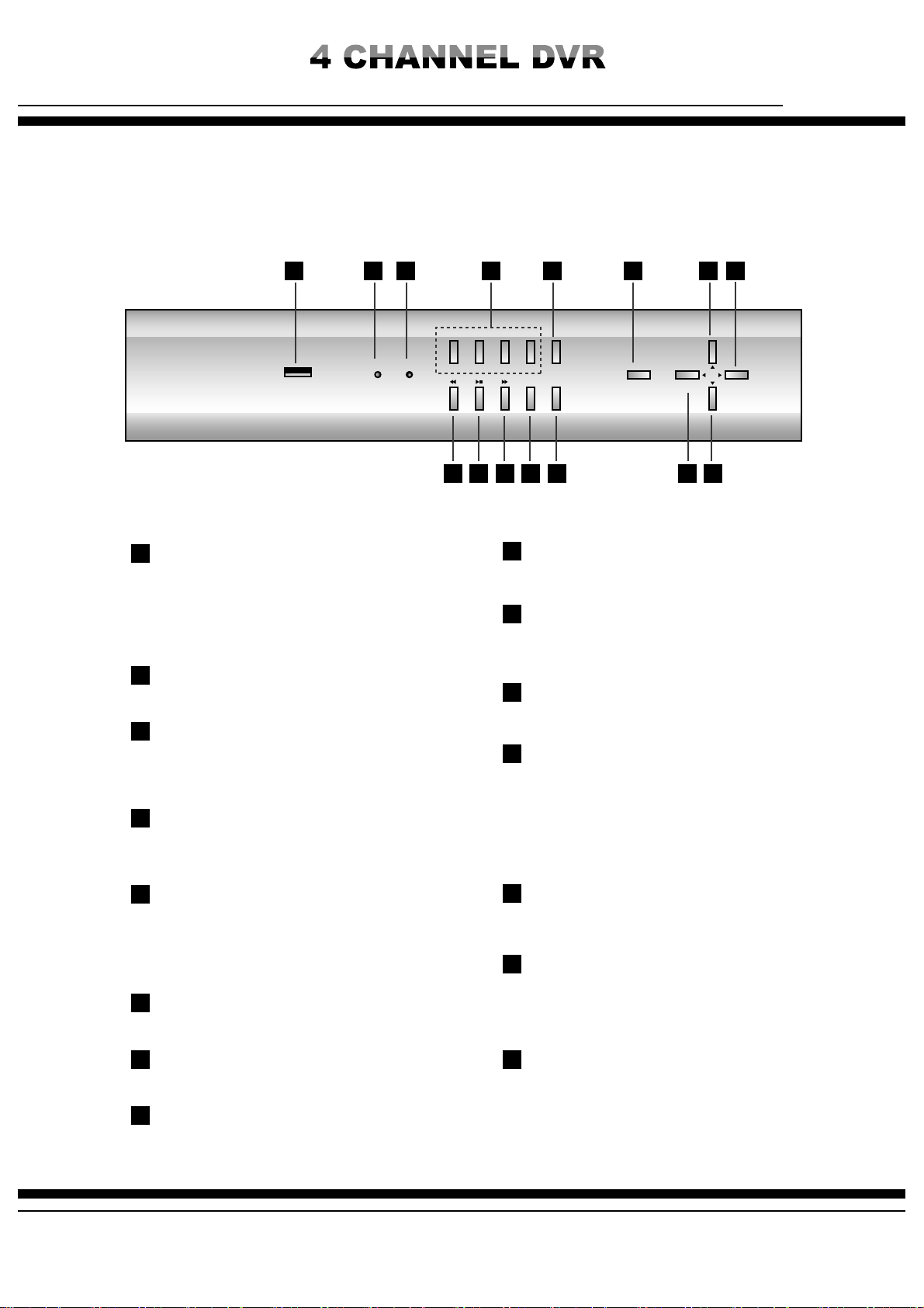
#6550/4"/%'6/$5*0/4
'SPOU7JFX
1
1
9
9
10
10
11
11
12
12
13
13
14
14 15
15
2
2
3
3
4
4
5
5
6
6
7
7
8
8

Digital Video Recorder
MANUAL
CAUTION
CH1
RS-485 ALARM OUT/IN
CH1 CH2 CH3 CH4 OUT
CH2 CH3 CH4
LAN VGA S-VIDEO SPOT OUT
MAIN OUT
VIDEO
IN
LOOP
OUT
DC 12V
POWER
3FBSTJEFWJFX
1
9
10
11
12
2
3
4
5
6
7
8
13
1
9 10 11 12 13
2 3 4 5 6
7 8
[Note] Electrically matched adaptor must be used. Unqualified adaptor use may cause problems
on system such as intermittent system rebooting, power off and etc. Warranty service will not cover
such system damage by improper adopter use.

Digital Video Recorder
MANUAL
)%%*/45"--"5*0/
[Note for adding HDD]
ㆍ Pay special attention to avoid wrong cable connection or scratch on cables. (It may cause product failure or fire)
ㆍ Be careful not to get injured by a sharp edge inside the product.
ㆍ Be careful not to lose any of unscrewed pieces or parts. Incomplete fixing and assembling may cause operational
failure or malfunction.
HDD installation procedure
1. Unscrews 4 pieces on the right and left sides respectively and unscrew 5 pieces at the rear to remove the cover.
User can install the HDD into DVR, but, since there are many parts and factors inside the product, it requires special
care in case of wiring and connections. Otherwise it may cause electric shock, troubles, faults on the product and etc.
Further improper HDD installation may generate HDD detection problem or improper operation, so it is advisable initial
HDD or additional HDD installation work should be handled by authorized engineer from the agent where the product
was purchased.

Digital Video Recorder
MANUAL
3. Unscrew the pieces from the HDD rack to mount the HDD in case of two HDDs installation (Refer to below
‘Second HDD installation’)
One HDD installation
Second HDD installation
2. Connect data bus cable to the board bringing the red part of the cable in touch with the groove on the connector
11
22
3
3
Install HDD on front side and set HDD as “Master”
Connect HDD cable
Connect HDD power cable
Connect HDD power cable
1
2
3
As shown on picture, place second HDD and set
HDD as ‘Slave’
Connect HDD cable
1
23
Digital Video Recorder
MANUAL
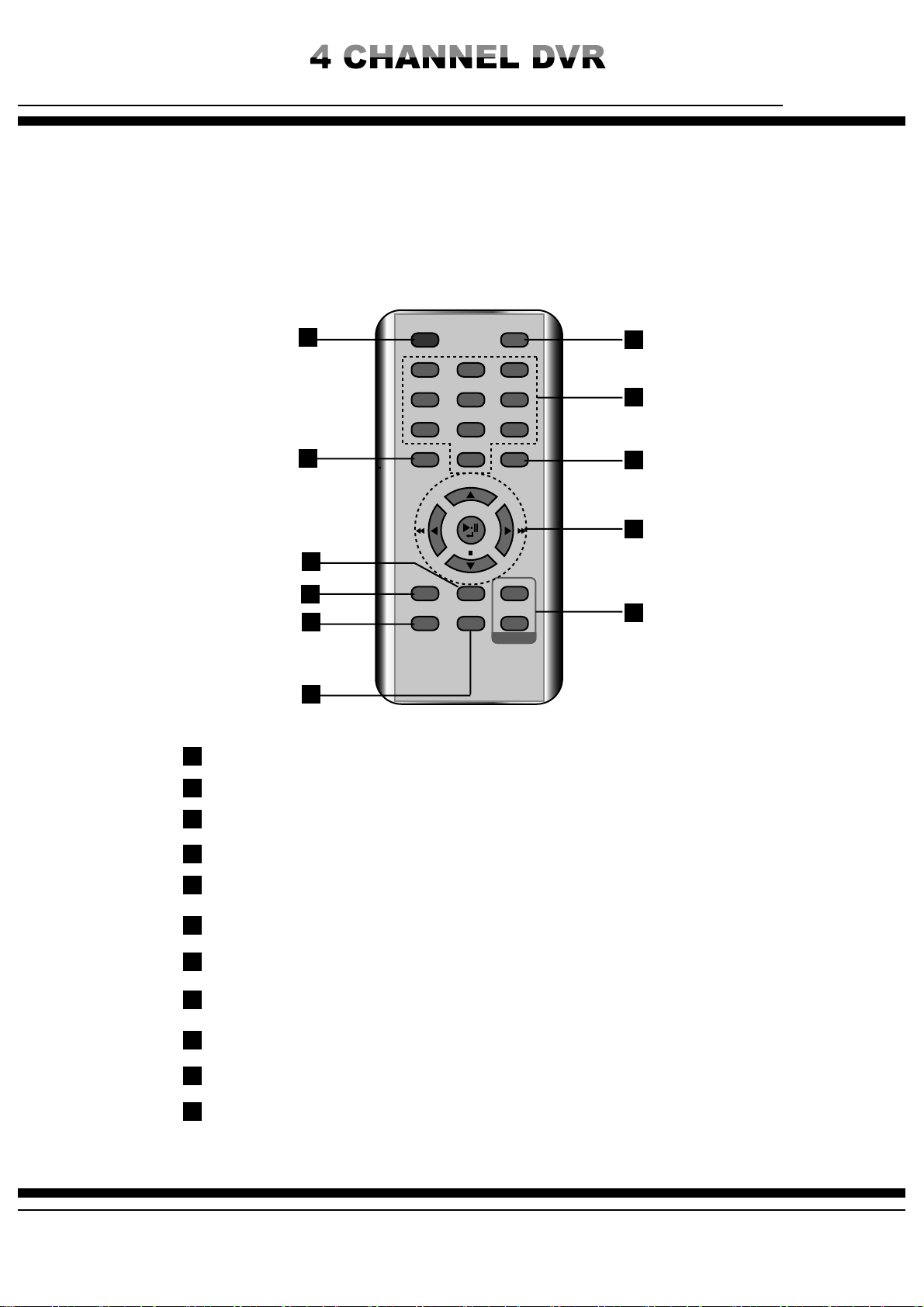
)085064&3&.05&$0/530--&3
1
2
3
4
5
6
7
8
9
10
11
ID
123
456
789
PIP
SPLIT
AUDIO
SEQ PTZ
BACK UP
0
MENU
SEARCH
REC
SCHEDULE
EMERGENCY
1
2
3
4
5
6
7
8
9
10
11
ID Button : By assigning DVR ID, it allows the user to control multiple DVRs with one remote controller.
SEARCH Button : To search recorded data from the HDD
Channel selection button: To select channel or to enter password
PIP button: To call PIP screen and PIP position changes whenever push the button
Backup button: To backup data to USB memory stick
Audio button: To select audio listening mode of each channel
SEQ Button: Auto sequence screen display button
PTZ Button : PTZ camera button
Menu button: To call system menu
Direction and playback speed control button
Record button (Emergency / Schedule)
By using this easy to carry remote controller, user can use all the functions of FORVR450 and can separately control multi
numbers of DVRs installed in the same place.
Table of contents
Other 4NSYS DVR manuals


