4qd PRO-160 Series User manual

PRO-160 V2.3/2 04/20 Page 1 www.4qd.co.uk
Instruction Manual
PRO-160 Series Controllers
PRO-160-S/HC/HV/HCV
Rev 3, Firmware Version 2.3
Contents
Section Page Section Page
1. Introduction.................................2
2. Do's and Don’ts ..........................2
3. Getting Started............................2
4. Control Connections..................3
5. Auxiliary Input 1..........................4
6. Auxiliary Input 2..........................4
7. Thermistor input.........................5
8. Radio Control Input and BEC....5
9. Power Connections....................6
10. Display.........................................7
11. Programming..............................7
12. Forward / Reverse Settings .......9
13. General Settings.........................9
14. Throttle settings .......................10
15. Advanced settings....................10
16. Using the “learn” function .......10
17. Power-up options .....................11
18. System settings [inc reset]......11
19.Mounting ...................................11
20. Display mounting......................12
21. Service.......................................12
22. Default profile settings.............13
23. Specifications ...........................15

PRO-160 V2.3/2 04/20 Page 2 www.4qd.co.uk
1. Introduction
The Pro-160 is an advanced digital PWM motor controller for currents up to 200A.
It uses a specialist microprocessor to control a full H-bridge design that does not
require relays for reversing. The display provides key information to the operator,
and can be mounted separately to the controller if required. It has a full range of
features and is very easy to configure if required.
2. Do's and Don’ts
Warning –the Pro-160 does not have reverse polarity protection.
Connecting the battery wires incorrectly WILL destroy the controller.
Do
•Do read the instructions fully
before installing.
•Do take care to connect the
battery wires with the correct
polarity.
•Do fit a motor suppression
capacitor, and ferrite rings.
•Do twist the motor wires
together if possible.
•Do call 4QD if you are
uncertain about something.
Do not
•Do not allow water to get onto
the circuit boards.
3. Getting Started
•Remove the four screws that hold the
cover to the end plates and lift off the
cover.
•The Pro-160 is supplied with the keymat
ribbon cable not connected to its socket.
This should only be plugged in once the
Pro-160 has been fixed in position, the
control and power connections made, and
you are ready to start operation.

PRO-160 V2.3/2 04/20 Page 3 www.4qd.co.uk
4. Control Connections
The control input sockets are shown below.
The main control input and brake should be wired as shown below [they are
compatible with Pro-120/150 and DNO/VTX installations].

PRO-160 V2.3/2 04/20 Page 4 www.4qd.co.uk
5. Auxiliary Input 1
Has the following functions.
A -Deadman’s handle. There are 2 modes of deadman operation. In “std” if this
pin is connected to Gnd then the Pro-160 will follow the active profile ramp
down to zero, it will ramp up again when Gnd is removed. In “safe” this pin
must be connected to Gnd for operation to start.
B -Alternate profile. If this pin is connected to Gnd the Pro-160 will start up in
the alternate profile defined in the profile that was operating without the Gnd
present. This allows easy switching between any two profiles.
C -Limit 1. If this pin is connected to Gnd then the Pro-160 will invoke the
behavior defined for this limit. This will be available in version 2.4.
D -Emergency stop. If this pin is connected to Gnd then the Pro-160 will stop
immediately. It will not start up again until the Gnd is removed, and the ignition
has been turned off / on.
6. Auxiliary Input 2
Has the following functions.
C - Speed. This pin can be used with our speed sensor kit [part number SEN-SPD]
for top speed limiting. The sensor is powered by the BEC supply and delivers a 5V
pulse proportional to the speed of the shaft that the magnet is attached to.

PRO-160 V2.3/2 04/20 Page 5 www.4qd.co.uk
7. Thermistor input
Can be used to connect 1 or 2 sensors to monitor external temperatures.
Sensor X is connected to C and D, Sensor Y to A and B.
Once the sensors have been installed they must be enabled in the profile menu.
8. Radio Control Input and BEC
The Pro-160 will accept a standard hobbyist radio control servo signal directly
from a receiver. The receiver should be connected to pins B, C, and D. Pin D is
linked to pin A by Lk1, this can be removed if a 4 wire radio connection is
required.
The Pro-160 is pre-programmed to work with the majority of radio receivers.
Profiles 7 and 8 are configured for RC single ended and RC joystick use.
Depending on your radio system you may need to use the RC learn function to
properly match the Pro-160 to your receiver output.
Sensors X and Y should be 4QD
part number SEN-TMP.

PRO-160 V2.3/2 04/20 Page 6 www.4qd.co.uk
The RDO port can act as a BEC for currents up to 1A. Pin B of the adjacent BEC
port can be used in parallel to increase this to 2A if required.
9. Power Connections
The power connections are M6 diameter threaded posts. The wire used should
be of a diameter appropriate for the load envisaged.
Battery Wiring
Keep the battery wiring as short as possible to reduce the load on the main
capacitors.
Motor Wiring
To reduce electrical noise the motor wires should be kept close to each other and
twisted together if possible. A 10nF 100V disc ceramic motor suppression
capacitor should be fitted across the brushes of the motor. Ferrite rings should be
fitted on the motor wires. See the knowledgebase on our website for more
information on noise suppression.
If the motor rotates in the wrong direction, swap over the M+ and M- wires.
Battery Circuit Breaker
A circuit breaker or fuse should be fitted in the battery wiring. The rating should
be above that of the motors normal operating current.
A battery isolator switch should also be fitted to provide an emergency
disconnection capability. In some applications such an isolator is a legal
requirement.
Contactor
The Pro-160 has provision to drive a failsafe contactor which can provide an
emergency disconnection in the event of a controller failure. Details of how to
implement this feature are in the knowledgebase on our website.

PRO-160 V2.3/2 04/20 Page 7 www.4qd.co.uk
10. Display
The Pro-160 has a 2 line display to display useful information during operation
and programming.
During operation the display will show information in this format:
Volts = battery voltage.
Duty cycle = % of battery voltage being applied to the motor [- = reverse].
Motor current = instantaneous motor current in amps.
Profile = profile currently selected [suffix R indicates reverse].
Temp = temperature in ‘C. Prefix C denotes controller temp, prefix X / Y denotes
sensor X / Y temp. X and Y only displayed if switched on in software.
Battery current = average current being drawn from the battery in amps. Note the
difference between this and motor current.
The display also shows any alert or fault information.
A display adaptor board is available that allows the display and / or keypad to be
mounted remotely from the Pro-160.
11. Programming
The Pro-160 has 15 profiles, 14 of which can be edited to suit the user. Each
profile has a number of settings which control various aspects of the controller’s
behavior. We have configured the first 9 profiles with values that are a good
starting point for the most popular applications, full details are in the table at the
end of the manual.
It is not possible to make changes to profile 01, to save changes you must first
select another profile.
To edit the settings the SEL button should be held down while turning on the
ignition, you can then navigate through the options and settings as shown in the
menu structure below. Remember to use the menu option to save changes.

PRO-160 V2.3/2 04/20 Page 8 www.4qd.co.uk

PRO-160 V2.3/2 04/20 Page 9 www.4qd.co.uk
12. Forward / Reverse Settings
12.1 “Accel ramp”. Sets the time taken to reach Max PWM. 1 - 300 corresponds to 0.1
- 30 seconds.
12.2 “Decel ramp”. Sets the time taken to slow down to zero. 1 - 300 corresponds to
0.1 - 30 seconds.
12.3 “Max PWM”. Sets the maximum percentage of battery voltage that can be applied
to the motor.
12.4 “Regen limit”. Sets the upper limit of the regen braking current. This works in
conjunction with “Decel ramp” to control the braking effect.
A slow “Decel ramp” [high number] will generate low regen currents. A low
“Regen limit” will allow the motor to coast more.
13. General Settings
13.1 “Current limit”. Sets the maximum motor current that the Pro-160 will allow. If the
motor / load tries to exceed this value the PWM duty cycle will be reduced.This
can be used to provide a torque limiting function.
13.2 “Reverse beep”. Switches the reversing beeper on or off.
13.3 “Low battery”. Allows the alert and cut-off voltages to be set. When the low
battery alert activates, the Pro-160 will reduce its maximum speed by 50%.
13.4 “Parking brake”. Sets the time delay before the parking brake is applied, and the
power threshold that must be reached before the parking brake is released.
13.5 “Alternate profile”. Sets the profile to be selected if the Alt-P input is activated,
and the Pro-160 re-started.
13.6 “Deadman”. Switches between push to stop [std] and push to go [safe] modes.
Note; There is also a “System current limit” which is not user adjustable. If the
load tries to exceed this value a message is shown, and the controller will shut
down to protect itself.

PRO-160 V2.3/2 04/20 Page 10 www.4qd.co.uk
14. Throttle settings
14.1 “Input mode”. Selects the input to be used. Pot will use the signal applied to pin E
of the control port. RC will use the RDO port. Volt will also use the signal on pin E
of the control port but the pot fault checks will be disabled.
14.2 “Joystick”. Selects either single ended or joystick [center-off / wig-wag] mode.
14.3 “Deadband”. Sets the amount of input required before the output starts [joystick
mode only].
14.4 “Pot learn”. See Section 16. [also used for Volt mode].
14.5 “RC learn.” See Section 16.
14.6 “Lockout”. Prevents the motor starting if the Pro-160 is switched on with the
throttle not at zero. This setting defines the throttle position above which this
occurs. Lockout is disabled in Volt mode.
15. Advanced settings
15.1 “Speed sensor”. Switches on the speed sensor input. “Learn mode” here
displays the actual rpm being measured. “MAX rpm” sets the limit beyond
which the controller will reduce the power. Full details of the speed sensor
function are available on our website.
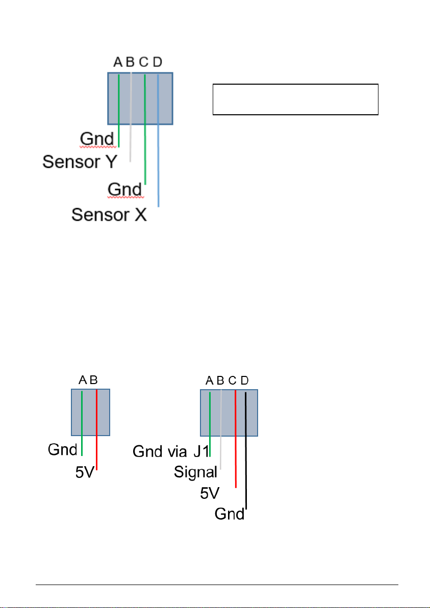
15.2 “Temperature”. Switches on the external temperature sensors X and / or Y. Each
sensor can have its own warning level set. Once switched on the Pro-160 will
display each sensor temperature in turn. Note: the controller sensor [C] is
calibrated differently to the X and Y sensors, they may not give exactly the same
readings at start up.
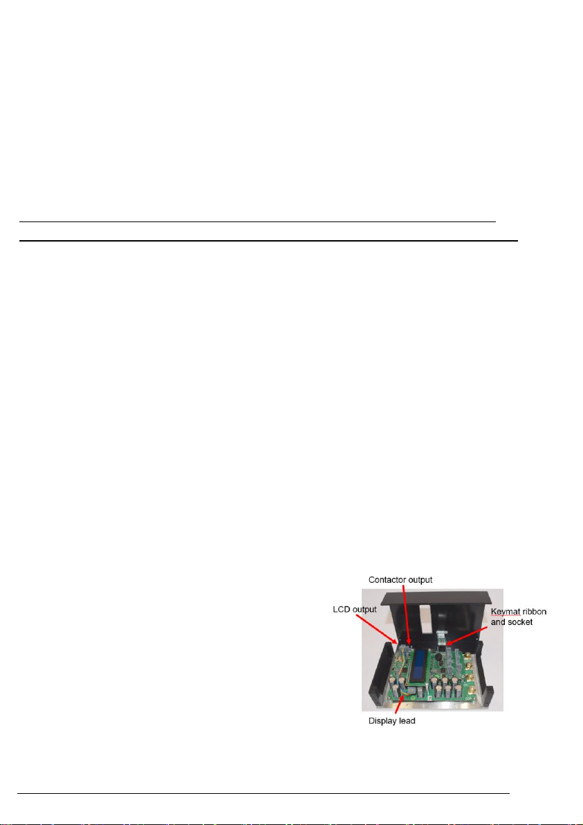
15.3 “Contactor”. Changes the controller to contactor mode. See the knowledge base
on our website for more details.
16. Using the “learn” function
The “learn”function allow you to match zero speed, full forward, and full reverse
from the Pro-160 to specific input signals from your pot, radio control receiver, or
other input source.
16.1 Set either “Pot learn” or “RC learn”active [only one per profile].
16.2 Select “Learn zero”and press SEL, the Pro-160 will show a number related to the
value detected from the pot [or other input].
16.3 Set the pot, transmitter stick, or other input to the position you want to have as
zero, and press SEL to capture the associated number.
16.4 Repeat steps 15.2 –15.3 for “Learn max forward” and “Learn max reverse”
16.5 Use BACK to return to the main menu and then save changes.

PRO-160 V2.3/2 04/20 Page 11 www.4qd.co.uk
Notes:
•If you are not using “Joystick” mode, you should set “Learn max reverse”
to the same value as “Learn max forward”. Reverse is then selected by
the reverse switch.
•Volt mode uses the “Pot learn” function for learning.
17. Power-up options
Power on with SEL pressed enters set-up mode.
Power on with DOWN pressed will start up with profile 1. This is an emergency
start option to be used should a system 'EEPROM' error occur.
18. System settings [inc reset]
18.1 About. Gives information on the model, software version, and serial number.
18.2 Factory reset. Allows the user to reset the Pro-160 to factory settings.
18.3 Firmware update. Allows new software to be installed via the uSD card reader.
Switch off the Pro-160, insert the uSD card containing the new software into the
card holder, and switch on again with SEL pressed.
Navigate through the system settings menu to “Firmware” and then follow
instructions. Remove the uSD card when finished.
19. Mounting
The Pro-160 has 4 M5 threaded mounting holes in the baseplate, shown in green
in the diagram below.

PRO-160 V2.3/2 04/20 Page 12 www.4qd.co.uk
If the operating temperature of the Pro-160 regularly gets above 50’C we
recommend fitting either additional heatsinking and / or cooling. A cooling fan can
be driven from the parking brake socket. Uprated heatsinks will be available from
our website.
20. Display mounting
The LCD display can be detached from its normal place on the control board and
mounted in a more convenient location for the operator. There is an optional
display / adaptor board which combines a display mounting place with an
alternative keypad.
21. Service
The Pro-160 has a 12 month warranty. Please see the service section of our
website for full details.
It is also worth checking the troubleshooting section of our website for advice on
how to find common installation problems.
The display
adaptor board and
cables can be
found on our
website.

PRO-160 V2.3/2 04/20 Page 13 www.4qd.co.uk
22. Default profile settings

PRO-160 V2.3/2 04/20 Page 14 www.4qd.co.uk

PRO-160 V2.3/2 04/20 Page 15 www.4qd.co.uk
23. Specifications
Technical Specification
Pro-160
160-S
160-HC
160-HV
160-HCV
Nominal voltage range
12 - 48
12 - 84
Minimum / max voltage
10.5 - 65
10.5 - 96
Motor current A [max]
140
200
140
200
Motor current A [1 minute]
140
200
140
200
Motor current A
[continuous]
Depends on cooling
Programmable
parameters
See parameter table
Dimensions [mm]
181 x 121 x 50
Weight [g]
~700g
Power connections
M6 studs
Input
5k –25k pot, RC [PWM], 0 –4.7V
Reverse polarity
protection
N
Overvoltage protection
Y [65V]
Y [95V]
Pot fault protection
Y [50k]
Thermal protection
Y @ 65’C [also for 2 external sensors]
Joystick/Wig-wag input
Y
Radio Control
Y
Parking brake
1A max, delay and threshold programmable
Inhibit function
Emergency stop input
Other inputs
Deadman, alt profile, speed, 2 x thermistor, 2
x limit, 2 x spare
Powerdown state
Diode bridge across motor
Closed loop RPM control
Via software update
Ignition, electronic
Y
Safety contactor circuit
Y

PRO-160 V2.3/2 04/20 Page 16 www.4qd.co.uk
Technical Specification
Pro-160
160-S
160-HC
160-HV
160-HCV
Heatsink
Standard [advanced air cooled soon]
Double heading
Y [also comms board coming soon]
Switching frequency
20 kHz
Quadrants
4
Other manuals for PRO-160 Series
1
This manual suits for next models
4
Table of contents
Other 4qd Controllers manuals
Popular Controllers manuals by other brands

Allen-Bradley
Allen-Bradley 1769-L32E CompactLogix 5332E installation instructions

Toa
Toa IP-1000CI user manual

Munters
Munters Green RTU RX installation manual

Broadcast Tools
Broadcast Tools Mixer Buddy II Installation and operation manual

Emerson
Emerson EXD-SH1 operating instructions

Sentera Controls
Sentera Controls DRPUM Mounting and operating instructions