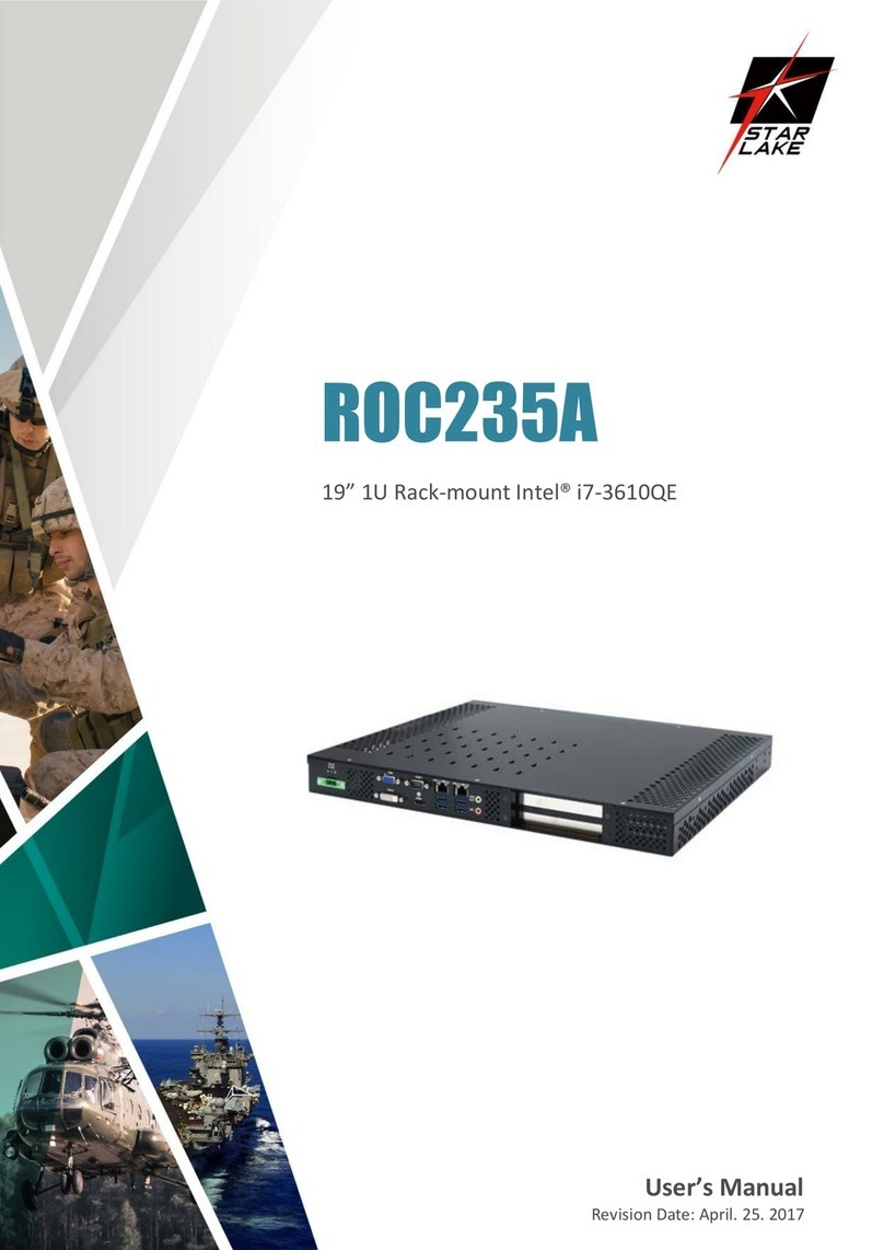
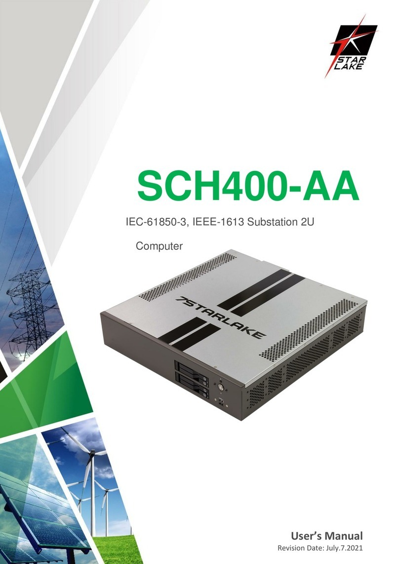
7starlake SR800 User manual

User’s Manual
Revision Date: Jun. 25. 2019
SR800
MIL-STD Rugged Computer
User’s Manual

SR800 User’s Manual
Revision Date: Jun. 25. 2019
1
Safety Information
Electrical safety
To prevent electrical shock hazard, disconnect the power cable from the electrical outlet before
relocating the system.
When adding or removing devices to or from the system, ensure that the power cables for the
devices are unplugged before the signal cables are connected. If possible, disconnect all power cables
from the existing system before you add a device.
Before connecting or removing signal cables from the motherboard, ensure that all power cables are
unplugged.
Seek professional assistance before using an adapter or extension cord. These devices could interrupt
the grounding circuit.
Make sure that your power supply is set to the correct voltage in your area.
If you are not sure about the voltage of the electrical outlet you are using, contact your local power
company.
If the power supply is broken, do not try to fix it by yourself. Contact a qualified service technician or
your local distributor.
Operation safety
Before installing the motherboard and adding devices on it, carefully read all the manuals that came
with the package.
Before using the product, make sure all cables are correctly connected and the power cables are not
damaged. If you detect any damage, contact your dealer immediately.
To avoid short circuits, keep paper clips, screws, and staples away from connectors, slots, sockets and
circuitry.
Avoid dust, humidity, and temperature extremes. Do not place the product in any area where it may
become wet.
Place the product on a stable surface.
If you encounter any technical problems with the product, contact your local distributor
Statement
All rights reserved. No part of this publication may be reproduced in any form or by any means,
without prior written permission from the publisher.
All trademarks are the properties of the respective owners.
All product specifications are subject to change without prior notice

SR800 User’s Manual
Revision Date: Jun. 25. 2019
2
Revision History
Revision
Date (yyyy/mm/dd)
Changes
Version 1.0
2018/10/05
Initial release
V1.1
2019/06/25
Change Product photo &
Status LED specification
Packing list
□ SR800 Fanless Rugged System
□ CD (Driver + Quick Installation Guide)
Ordering Information
Model Number
Description
SR800
Rugged Fanless military computer with Intel Xeon D‐1587
processor, 24V DC‐IN, Operating Temperature 0 to 50°C

SR800 User’s Manual
Revision Date: Jun. 25. 2019
3
Table of contents
Safety Information .............................................................................................................................................1
Electrical safety..............................................................................................................................................1
Operation safety ............................................................................................................................................1
Statement ......................................................................................................................................................1
Revision History..................................................................................................................................................2
Packing list..........................................................................................................................................................2
Ordering Information.........................................................................................................................................2
Chapter 1: Product Introduction ........................................................................................................................4
1-1 Key Features......................................................................................................................................4
1.2 Mechanical Dimensions ........................................................................................................................7
1.3 Panel Component.....................................................................................................................................8
Chapter 2: Jumpers and Connectors Locations ..................................................................................................9
2.1 Rear Panel Connector Pin Definitions ......................................................................................................9
2.2 LED Indication ........................................................................................................................................11
Chapter 3 BIOS .................................................................................................................................................12
3-1 Introduction...........................................................................................................................................12
3-2 Main Setup.............................................................................................................................................13
3-3 Advanced Setup Configurations.............................................................................................................15
3-4 Event Logs..............................................................................................................................................36
3-5 IPMI........................................................................................................................................................38
3-6 Security Settings ....................................................................................................................................41
3-7 Boot Settings..........................................................................................................................................44
3-8 Save & Exit.............................................................................................................................................46

SR800 User’s Manual
Revision Date: Jun. 25. 2019
4
Chapter 1: Product Introduction
1-1 Key Features
System
High Performance
Processor
Intel® Xeon® Processor D-1587 (Frequency 1.7GHz, Turbo Boost Frequency up to 2.3GHz),
16-Core, 32 Thread Support, 24MB SmartCache. Build-in Turbo Boost Technology 2.0, VPro
and Hyper-Threading support.
Memory type
4 x DIMMs Up to 128GB ECC RDIMM DDR4 2133MHz
Chipset
SoC, integrated with CPU
Display
Graphics Processor
ASPEED AST2400
Resolution
Up to 1920x1200@60Hz 32bpp
Storage
HDD/SSD
2 x 2.5" SSD
Ethernet
Ethernet
1 x Intel I350-AM2 Gigabit LAN Interfaces (10/100/1000Mbps)
Rear I/O
VGA
1 (M20 connector)
IPMI
1 (M20 connector)
USB3.0
2 (M20 connector)
USB2.0
1 (M20 connector)
X1 (DC-IN)
1 ( Souriau 8ST7-10G05PN)
X5 (Gigabit Ethernet)
1 ( Souriau 8ST7-10G35SA)
X6 (100M Ethernet)
1 ( Souriau 8ST7-08G35SN)
X9 (RS232)
1 ( Souriau 8ST7-10G35SB)
Side I/O
Button
1 x Secure Erase Button (SSD2 support AES Secure Erase)
1 x Power Switch with Dedicated LED
HDD Tray
1 x Dual 2.5" HDD/SSD Easy Swap Tray
CMOS Battery Tray
1 x Removable CR2032 CMOS Battery Tray
Dedicated LED
1 x Red LED (OVHT) 5 x Green LEDs (2 x LAN, 1 x PWR, 1 x SSD, 1 x RDY)

SR800 User’s Manual
Revision Date: Jun. 25. 2019
5
Power Requirement
Power Input
MIL-STD-1275, MIL-STD 704 and DO-160 power supply ,12 to 40V (150W max)
Applications,
Operating System
Applications
Commercial and Military Platforms Requiring Compliance to MIL-STD-810G Embedded
Computing, Process Control, Intelligent Automation and manufacturing applications
where Harsh Temperature, Shock, Vibration, Altitude, Dust and EMI Conditions. Used in
all aspects of the military.
Operating System
Windows 10 64Bit, Windows Server 2008 R2, Windows Server 2012 R2, Windows Server
2016, Ubuntu14.04, Fedora 20/23, RedHat Linux EL 7.1/7.2, Vmware ESXi 6.0, ESXi 6.5
Physical
Dimension (W x D x H)
260 x 350 x 102mm (10.24" x 13.78" x 4.02")
Weight
9.6 Kg (21.16lbs)
Chassis
Aluminum Alloy, Corrosion Resistant
Finish
Anodic aluminum oxide (Color Iron gray)
Cooling
Natural Passive Convection/Conduction. No Moving Parts
Ingress Protection
IP65
Environmental
MIL-STD-810G Test
Method 507.5, Procedure II (Temperature & Humidity)
Method 516.6 Shock-Procedure V Non-Operating (Mechanical Shock) Method 516.6
Shock-Procedure I Operating (Mechanical Shock)
Method 514.6 Vibration Category 24/Non-Operating (Category 20 & 24, Vibration)
Method 514.6 Vibration Category 20/Operating (Category 20 & 24, Vibration)
Method 501.5, Procedure I (Storage/High Temperature)
Method 501.5, Procedure II (Operation/High Temperature)
Method 502.5, Procedure I (Storage/Low Temperature)
Method 502.5, Procedure II (Operation/Low Temperature)
Method 503.5, Procedure I (Temperature shock)
Reliability
No Moving Parts; Passive Cooling. Designed & Manufactured using ISO 9001/2000
Certified Quality Program.
EMC compliance
MIL-STD-461E :
CE102 basic curve, 10kHz - 30 MHz
RE102-4, (1.5 MHz) -30 MHz - 5 GHz
RS103, 1.5 MHz - 5 GHz, 50 V/m equal for all frequencies

SR800 User’s Manual
Revision Date: Jun. 25. 2019
6
EN 61000-4-2: Air discharge: 8 kV, Contact discharge: 6kV
EN 61000-4-4: Signal and DC-Net: 1 kV
EN 61000-4-5: Leads vs. ground potential 1kV, Signal und DC-Net: 0.5 kV EN 61000-4-2:
Air discharge: 8 kV, Contact discharge: 6kV
EN 61000-4-4: Signal and DC-Net: 1 kV EN 61000-4-5: Leads vs. ground potential 1kV,
Signal und DC-Net: 0.5 kV
EN 61000-4-2: Air discharge: 8 kV, Contact discharge: 6kV
EN 61000-4-4: Signal and DC-Net: 1 kV
EN 61000-4-5: Leads vs. ground potential 1kV, Signal und DC-Net: 0.5 kV EN 55022, class
A
EN 61000-4-3: 10V/m
CE
Operating Temperature
0 to 50°C
Storage Temperature
-40 to 85°C
*Specifications are subject to change without notice*

SR800 User’s Manual
Revision Date: Jun. 25. 2019
7
1.2 Mechanical Dimensions

SR800 User’s Manual
Revision Date: Jun. 25. 2019
8
1.3 Panel Component

SR800 User’s Manual
Revision Date: Jun. 25. 2019
9
Chapter 2: Jumpers and Connectors Locations
2.1 Rear Panel Connector Pin Definitions

SR800 User’s Manual
Revision Date: Jun. 25. 2019
10

SR800 User’s Manual
Revision Date: Jun. 25. 2019
11
2.2 LED Indication

SR800 User’s Manual
Revision Date: Jun. 25. 2019
12
Chapter 3 BIOS
3-1 Introduction

SR800 User’s Manual
Revision Date: Jun. 25. 2019
13
3-2 Main Setup

SR800 User’s Manual
Revision Date: Jun. 25. 2019
14

SR800 User’s Manual
Revision Date: Jun. 25. 2019
15
3-3 Advanced Setup Configurations

SR800 User’s Manual
Revision Date: Jun. 25. 2019
16

SR800 User’s Manual
Revision Date: Jun. 25. 2019
17

SR800 User’s Manual
Revision Date: Jun. 25. 2019
18

SR800 User’s Manual
Revision Date: Jun. 25. 2019
19
Table of contents
Other 7starlake Industrial PC manuals