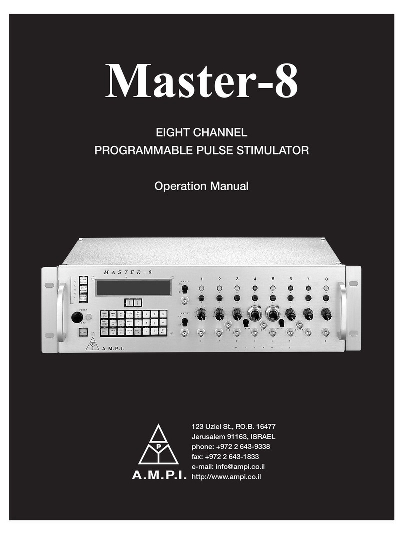
A.M.P.I. Master-9 User manual

Master-9
Programmable
Pulse Stimulator
User Manual

2
Thank you for purchasing Master-9 - the best pulse stimulator!
Master-9 is an advanced 9-channel pulse stimulator that offers many distinct and useful features.
Master-9 is user friendly, easy to learn, and simple to program using user-preprogrammed
paradigms.
Please read this manual carefully and familiar yourself with all of Master-9 unique and advanced
options.

3
Table of Contents
1GENERAL........................................................................................................................................ 5
1.1 OUTPUTS ............................................................................................................................... 5
1.2 PARADIGMS (CHAPTER 11) ......................................................................................................... 5
1.3CONTROLLING THE MASTER-9 ..................................................................................................... 5
1.4 FIRMWARE UPGRADES .............................................................................................................. 6
1.5 RECORD AND REPLAY INPUT WAVEFORMS (CHAPTER 13) .................................................................... 6
1.6 COMBINED OUTPUTS:OUT A, B, AND C........................................................................................ 6
1.7 EXTERNAL INPUTS:IN 1, 2, AND 3(CHAPTER 8)............................................................................... 6
1.8 CLOCKS (CHAPTER 15)............................................................................................................... 6
2FRONT & REAR PANEL ................................................................................................................... 7
2.1 FRONT PANEL .......................................................................................................................... 7
2.2 REAR PANEL ............................................................................................................................ 7
3THE TOUCH-SCREEN....................................................................................................................... 8
3.1 THE PARAMETERS OF THE CHANNELS ............................................................................................. 8
3.2 THE MANUAL TRIG KEYS ............................................................................................................ 9
3.3 THE CONNECTION TABLE............................................................................................................ 9
3.4 THE PARADIGM KEY .................................................................................................................. 9
3.5 THE VER KEY .......................................................................................................................... 9
3.6 THE CLOCK KEY ........................................................................................................................ 9
4OPERATING MODES......................................................................................................................10
4.1 SETTING THE OPERATING MODES .................................................................................................10
5SETTING PARAMETERS .................................................................................................................11
5.1 THE PARAMETERS ....................................................................................................................11
5.2 SETTING THE TIME PARAMETERS..................................................................................................11
5.3 SETTING THE "N" PARAMETER ....................................................................................................12
5.4 SETTING THE "V" AND "V"(ΔV STEPS)PARAMETERS .......................................................................12
6APPLICATIONS ..............................................................................................................................13
7THE CONNECTION TABLE ..............................................................................................................14
8TRIGGERING .................................................................................................................................15
8.1 MANUAL TRIGGERING ..............................................................................................................15
8.2 SETTING THE INTERNAL CONNECTIONS ..........................................................................................15
9THE EXTERNAL TRIGGER INPUTS...................................................................................................16
10 DISPLAYING OTHER CHANNELS.....................................................................................................17
10.1 DISPLAYING OTHER CHANNELS ....................................................................................................17
10.2 ELIMINATING CHANNELS FROM THE SCREEN VIEW ............................................................................17
10.3 ERASING ALL PARAMETERS OF A CHANNEL......................................................................................17
11 NINE STORED PARADIGMS ...........................................................................................................18
11.1 SWITCHING TO ANOTHER PARADIGM ............................................................................................18
11.2 COPYING PARADIGMS ..............................................................................................................18
11.3 CLEARING PARADIGMS .............................................................................................................18

4
12 DEMONSTRATION OF PROGRAMMING MASTER-9....................................................................... 19
13 CHANNEL 9: REPLAYING EXTERNAL WAVEFORMS........................................................................ 22
13.1 THE RUN MODE .................................................................................................................... 22
13.2 THE MEM MODE ................................................................................................................... 22
13.3 WAVEFORM AS EXCEL FILE ........................................................................................................ 22
13.3.1 Setting a waveform as Excel file: ................................................................................... 22
13.3.2 Long waveforms, up to 32K points ................................................................................ 22
13.3.3 Downloading the waveform from the PC to Master-9.................................................... 23
13.3.4 Running the saved waveform........................................................................................ 23
13.4 RECORD AND DELIVER A WAVEFORM FROM AN EXTERNAL SOURCE ....................................................... 25
13.4.1 Record a waveform from an external source ................................................................. 25
13.4.2 The SAVE key ................................................................................................................ 25
13.4.3 Replay the saved waveform .......................................................................................... 25
14 COMMUNICATION WITH A PC...................................................................................................... 26
15 CLOCKS......................................................................................................................................... 27
15.1 THE CLOCK (CLK)................................................................................................................... 27
15.2 THE STOPWATCH (SW)............................................................................................................ 27

5
1General
Master-9 is a 9-channel pulse stimulator designed for nerve and muscle stimulation procedures
and a broad range of neurophysiological stimulation requirements.
1.1 Outputs
Each channel delivers repetitive, single, train or twin outputs. The outputs can be set to
monophasic and biphasic pulses and ramp outputs.
All channels can be operated independently of each other, or synchronized to produce simple and
complex pulse patterns.
You can use some channels to stimulate your preparation, while using other channels to trigger
other instruments (oscilloscope, PC, etc.) in synchronization with the stimulation.
1.2 Paradigms (chapter 11)
Master-9 stores nine user-preprogrammed experiments (paradigms). Each paradigm can use all
nine channels. You can easily switch your setup to the selected paradigm.
This feature is very useful in the following cases:
When the current protocol requires modifications during the course of the experiment. You
can preset the modifications in different paradigms and then switch between the experiments
easily.
When several users of a setup run different experiments. Each user can retrieve his specific
settings from the Master-9 memory.
All parameters of the 9 paradigms are stored in the memory even after the power is switched off.
1.3 Controlling the Master-9
You can control the Master-9 as follows:
1. As a standalone unit –via its touch screen
2. Via your PC –using our MASTER-9 CONTROL software
3. From within your own application –using the Master-9 SDK
1. Controlling Master-9 via the touchscreen (chapter 3):
The touchscreen (TS) on the front panel displays all modes of operation and time parameters,
as well as a table of the internal connections between channels. You can set the channel
parameters by touching the TS with your finger or any stylus pen or standard pen. Do not
touch the screen with ink or sharp tools!

6
2. Controlling Master-9 via your PC, using our MASTER-9 CONTROL software:
You can see and modify all the parameters directly on your PC monitor using the MASTER-9
CONTROL Software.
Scheduler: The Scheduler is another powerful feature of this software. This tool allows you to
set a series of events to occur at scheduled times, such as triggering channels, switching
paradigms, modifying time parameters, etc.
3. Controlling Master-9 from within your own application (Master-9 SDK):
You can also program and control your experiment from within your own application or
software (LabView, Matlab, VBScript, etc.). Using the Master-9 SDK (Software
Development Kit) you can easily access all instructions of Master-9 in real-time from your
application or software, providing real-time feedback from your preparation.
1.4 Firmware Upgrades
Master-9 can be upgraded at any time with our firmware upgrades.
From time to time, be sure to check our website for new upgrades. Downloading and upgrading
your Master-9 is free of charge.
1.5 External Waveforms
Channel 9 can save external waveforms in two ways:
1. You can set an Excel file with the desired waveform and download it to channel 9 via the
USB cable.
2. Channel 9 can record input waveforms (such as action potential, sine wave, etc.). The
waveform can be recorded from an external source via the IN9 input. The waveform is saved
in the memory of channel 9.
The saved waveform can be replayed in all the operational modes –FREE-RUN, TRIG, TRAIN,
and TWIN modes.
1.6 Combined outputs: OUT A, B, and C
Using the connection table you can connect any combination of channels 1 - 9 to each other and to
each of the outputs A, B, and C. This way you can have complex patterns through a single output.
1.7 External inputs: IN 1, 2, and 3 (chapter 8)
Channels 1, 2 and 3 can receive external trigger inputs through the IN 1, 2, 3 inputs. This enables
the synchronization of channels with external devices.
1.8 Clocks (chapter 15)
In addition to its 9 channels, Master-9 features 2 internal clocks. The first counts the time in seconds up to
24 hours, while the other counts time in tenths of seconds, up to 1 hour.

7
2Front & Rear Panel
Figure 1
2.1 Front panel
The front panel consists of the following sections (see Figure 1):
Power Switch - located on the left side of the front panel.
Touchscreen (TS) - where the Master-9 parameters can be viewed and modified (Chapter 3).
Backlight switch - turns the TS backlight on & off..
Stylus pen - located at the bottom of the Master-9, under the power switch.
USB interface –used for:
Communicating and programming of the Master-9 by using a computer (Chapter 14).
Upgrading the Master-9 (firmware upgrades, Chapter 14).
Input section. The input section has 4 BNC sockets:
IN 1, 2, 3 inputs are used to externally trigger channels 1, 2 and 3 (Chapter 9).
IN 9 is an analog input for the recording channel 9 (Chapter 13).
Output Section:
a. Enable/Disable Switch - enables/disables all outputs of Master-9. This switch is useful
for cases where immediate stop of the stimulation is required. Make sure that this switch
is set to ENABLE.
b. 12 output BNC sockets and LEDs- Each of the 9 channels has an output BNC socket
and a LED that indicates the channel activity. There are 3 additional outputs A, B and C
for output combinations of the 9 channels.
2.2 Rear panel
The rear panel contains a switch to connect or disconnect the ground to/from the chassis.
This switch can be used to reduce the noise level of the system.

8
3The Touch-Screen
When the Master-9 is turned on, the following screen is displayed:
Figure 2
3.1 The parameters of the channels
The screen is divided vertically:
The right side of the screen displays the parameters of channels 1, 2, 3 and 4.
The definition column is displayed to the left of channel 1. This definition column defines the
heading of each row, as follows:
1. #- The top row shows the channel number.
2. M -Mode: The 2nd row defines the channel operating mode (see Chapter 4).
3. D - Duration: The 3rd row defines the pulse duration (see Chapter 5, figure 3) - the time that
elapses from the onset of the output pulse to its end.
4. L –deLay: The 4th row defines the delay time - the time that elapses from the beginning of
the input trigger to the beginning of the output pulse.
5. Interval: The 5th row defines the Interval time - the time that elapses between the beginning
of a pulse and the beginning of the following pulse (interval = 1/rate).
6. N –Number: The 6th row defines the number of pulses per train in the TRAIN mode.
7. V –Volt: The 7th row defines the pulse amplitude in volts.
8. S –Shape: The 8th row defines the shape of the pulse: Monopolar, Bipolar or Ramp.
9. v –ΔV: The 9th row defines the ΔV increment or decrement voltage steps, if applied.
Example: In Figure 2 above you see that each of the channels (1, 2, 3, 4) is in its default values as
follows: Set to OFF mode, duration time is set to D=1.0 msec. Delay time is set to L=0 µsec,

9
Interval time I=200 msec, N=5 pulses per TRAIN, V=10V, S=monophasic pulses, and v=0 -
meaning there are no voltage steps.
The screen displays 4 channels at a time, although all channels are operational as set. You can
choose which channels to display (Chapter 9).
3.2 The Manual Trig keys
The bottom line of the touch-screen contains the "1","2","3","4","5","6","7","8","9" keys.
These are the manual trig keys, which are used to manually trigger each individual channel.
3.3 The Connection Table
The left side of the screen displays the connection table. At the moment (as seen in figure 2
above), there are no connections between channels (see Chapter 7).
3.4 The Paradigm key
The Paradigm key is located above the connection table. It displays "P1", meaning that paradigm
#1 is currently running. Switch paradigms by pressing this key (Chapter 10).
3.5 The VER key
The VER key is located under the connection table. Pressing the VER key shows the current
version of the Master-9 (see Chapter 14). The VER key is also used for touchscreen calibration.
3.6 The Clock key
The Clock key is located under the VER key. Press this key to view and set the clock or stopwatch
(see Chapter 15).

10
4Operating Modes
Each of the 9 channels can operate in any of the following operating modes:
FREE-RUN - The channel delivers pulses continuously according to the programmed Duration
and Interval times. The channel is independent of the other channels.
TRAIN - Following a trigger, the channel delivers a train of N pulses according to the
programmed Delay, Duration and Interval times and the N parameter.
TRIG - Following a trigger, the channel delivers a single pulse according to the programmed
Delay and Duration times.
TWIN - Following a trigger, the channel delivers a pair of pulses according to the programmed
Delay, Duration and Interval times.
GATE - The channel delivers pulses continuously while it is gated (externally or internally from
the other channels). When the input stops, the channel deactivates. A new input reactivates the
channel.
DC - The channel is time-independent and can be turned on and off manually by pressing its
Manual Trig key.
4.1 Setting the operating modes
To set the mode of operation of a channel, first press the selected mode key and then choose the
desired mode.
Example 1: Setting channel #1 to the FREE-RUN mode:
1. Press M1 –(Row M Column 1 - This is the MODE of channel 1 - now OFF).
2. A new menu appears. You can choose any mode of operation for channel #1.
3. Press “FREE”. Channel #1 now delivers pulses continuously according to the set duration
(now 1 msec.) and interval times (now 200 msec).
Example 2: Setting channel #2 to TRAIN mode:
1. Press M2 –(the mode of channel 2 - now OFF). Press “TRAIN”.
2. Channel #2 is now in the TRAIN mode. You can trigger it externally, manually or internally
by the other channels (see Chapter 9).
3. Trigger it manually by pressing the "2" manual trigger key (at the bottom of the screen).
4. Channel #2 delivers a TRAIN of N=5 pulses.
Example 3: Setting channel #3 to DC mode:
Press M3, and then press “DC”. Channel #3 is now in the DC mode. It is time-independent and
delivers a continuous DC output. You can manually stop and start the output by pressing the "3"
manual trig key.
Example 4: Turning channel # 3 off: Press M3 (now DC) then press “OFF”.

11
5Setting Parameters
5.1 The parameters
The following parameters can be set for each channel:
D(duration) - Defines the time elapsing from the onset of the output pulse to its end (see
Figure 3).
L (delay) - Defines the time elapsing from the beginning of the input trigger to the beginning
of the output pulse.
I(interval) - Defines the time elapsing between the beginning of a pulse and the beginning of
the following pulse (interval = 1/rate).
interval
duration
delay
Figure 3
N- Defines the number of pulses per train in the TRAIN mode.
Nalso defines the number of ΔV steps if applied (ΔV ╪ 0) when in the TRAIN, FREE or
TRIG modes.
V (Voltage) - Defines the voltage amplitude of the pulses.
S(shape) - Defines if the pulses are monopolar or bipolar pulses, or ramps.
v(ΔV steps) - Defines the voltage increment (decrement) steps if applied.
5.2 Setting the time parameters
To set the time parameters (DURATION, DELAY or INTERVAL), first press the selected parameter key
and then the desired time.
Example: To set the interval time of channel 1 to 1 sec:
1. Press I1 –(now 200 msec).
2. A new menu appears. The present interval time is displayed on the top of the new menu.
3. Press: “1” then “sec”.

12
Notes:
1. While setting parameters you can use the “DEL”, the decimal point and the “ESC” keys.
2. You can also use the “▲” and “▼” keys.
The interval time defines the time elapsing between the beginning of a pulse and the beginning of
the following pulse (interval = 1/rate, Figure 3).
Important: When a channel is set to the FREE-RUN, TRAIN, TWIN or GATE mode, it must be
set so that INTERVAL > DURATION.
5.3 Setting the "N" parameter
Example: To set N=80 pulses per train for channel 1:
Press N1 (now 5), then press “80”, “ENTER”.
5.4 Setting the "V" and "v" (ΔV steps) Parameters
Example: To set V1= -5.02 V
Press V1 then press -5.02, Volt.
Ndefines the number of ΔV steps if applied (ΔV ╪ 0) when in the TRAIN, FREE or TRIG
modes.
The minimal step is ΔV = 0.01V (10 mV).
Table 1 - Parameters
Parameter
Min
Max
DURATION
4 sec
3600 sec
DELAY
4 sec
3999 sec
INTERVAL
40 sec
Interval> Duration
3999 sec
Ramp Duration
5 msec
60 sec
N
1
60,000
V, v
-10V
+10V
Output current –20 mA.

13
1
2
6Applications
Figure 4 shows how Master-9 works. Do not try to follow the programming just yet; Chapter 11
will enable you to practice programming of the Master-9.
interval
duration
delay
Channel 2 TRIG
triggered by #3
1
N=4
44
Output A: Out #4 + Out #5
Channel 3
FREE RUN
Run
Channel 4 TRAIN
triggered by #2
and #3
Channel 5
DC mode
Output A:
2
2
Figure 4
Triggered externally or manually
Turned on and off manually

14
7The Connection Table
P1
1
2
3
4
5
6
7
8
9
A
B
C
1
•
•
•
•
•
•
•
•
•
•
•
■
2
•
•
•
•
•
•
•
•
•
•
•
•
3
•
•
•
•
•
■
•
•
•
•
•
•
4
•
•
•
•
•
•
•
•
•
•
•
■
5
•
•
•
•
•
•
•
•
•
•
•
•
6
•
•
•
•
•
•
•
•
•
•
•
•
7
•
•
•
•
•
•
•
•
•
•
•
■
8
•
•
•
•
x
x
x
•
•
•
•
•
9
•
•
•
•
•
•
•
•
•
•
•
•
Figure 5: The connection table
The connection table displays all internal connections between channels and connections to
outputs A, B and C. The numbers that appear in the left column are the source channels, and the
numbers that appear on the top row are the target channels.
"•"Symbolizes that there is no connection between the channels.
The connection table (Figure 5) shows no connections from channels 2, 5, 6, and 9.
"■" Symbolizes that there is an operational connection between the two channels, i.e. there is a
connection between them and it fulfills the following conditions:
a. The source channel is not in the OFF mode and thus may send a trigger.
b. The target channel is in mode TRIG, TWIN, TRAIN or GATE (the modes in which the channel
expects a trigger input).
The table in figure 5 represents an operational connection from channel 3 to channel 6.
If you turn off channel 3 or channel 6 or if you set channel 6 to the FREE-RUN mode, this
connection will switch to a non-operational connection.
"x" Symbolizes that there is a connection between the two channels but it is a non-operational
connection. In the above table, all the internal outputs of channel 8 are non-operational (maybe
because channel 8 is OFF).
Each of the 9 channels can be connected to any number of other channels and to outputs A, B and
C. In the above example, output C outputs the summation/combination of channels 1, 4 and 7.
When you have a complex experiment in which many channels are involved, a simple glance at
the connection table gives you an instantaneous indication to what is being conducted in the
experiment.

15
8Triggering
In TRAIN, TWIN, TRIG or DC modes you can trigger the channel as follows:
1. Manual triggering.
2. Via the internal connections.
3. Via the external inputs 1, 2 and 3.
8.1 Manual triggering
In the TRAIN, TWIN, TRIG or DC modes you can trigger the channel manually.
The bottom line of the touch screen contains the "1", "2", "3", "4", "5", "6", "7", "8", "9" keys.
These are the manual trigger keys.
Example 1: When channel 3 is in the TRAIN mode, pressing manual trigger key "3" triggers the
channel.
Example 2: When channel 4 is in the DC mode, one press on the manual trigger key "4" turns
the channel on, and a second press turns it off.
When a channel is not in the TRAIN, TWIN, TRIG or DC modes, pressing its manual trigger key
does not affect the channel.
8.2 Setting the internal connections
In the TRAIN, TWIN, TRIG or GATE modes, you can trigger or gate the channel internally by
other channels. The proper connection should be set in the connection table as follows:
1. Press anywhere inside the connection table. A new screen with a larger connection table
appears.
2. The channels that appear on the left column are the source channels, and the channels that
appear on the top row are the target channels.
3. Example: To connect channel 2 to trigger channel 3, press the point that connects channel 2
(left column) to channel 3 (top row).
Note: The level or polarity of the output of the source channel does not affect the triggering.
4. To disconnect an existing connection, press the connection symbol.
5. Press the "RETURN" key to return to the main screen.

16
9The External Trigger Inputs
In TRAIN, TWIN, TRIG or GATE modes, channels 1, 2 and 3 can be triggered or gated
externally through the BNC inputs IN 1, 2, or 3. Channels 1, 2 and 3 can activate the other
channels internally.
The external input must be in the range of 3V to 10V.

17
10 Displaying Other Channels
10.1 Displaying other channels
4 channels are displayed at a time. You can choose which channels to display.
Example: Right now channels 1, 2, 3 and 4 are displayed. To switch channel 3 with channel 8:
1. Press on the channel number “3”. A new menu appears.
2. Press “8”. The screen will now display channels 1, 2, 8 and 4.
Note: Channel 3 continues operating as before.
10.2 Eliminating channels from the screen view
If you are using less than 4 channels, you can set the screen to display only those channels, which
would be more convenient.
Example: The screen displays channels 1, 2, 8 and 4.
3. To eliminate channel 4 from view press on the channel number “4”.
4. A new menu appears. Press "0".
5. Now the screen displays three channels only: 1, 2 and 8.
Channel 4 no longer appears on the screen but continues to operate as set.
10.3 Erasing all parameters of a channel
Example: Erasing all current parameters of channel 2:
1. Press the channel number "2" then press “Clr”.
Channel 2 erases all its parameters and restores the default parameters.

18
11 Nine Stored Paradigms
A paradigm specifies the modes and parameters of all the channels and their internal connections.
Master-9 stores nine different programmed paradigms.
11.1 Switching to another paradigm
Example 1: To switch to paradigm number 7:
Press the key "Px" (x=1,2..9 –x is the present paradigm number), then "switch to", "7".
You don't have to worry about saving the previous paradigm, each instruction is saved the
moment you enter it.
Example 2: To switch to paradigm 1:
Press key "P7" then "switch to", "1".
11.2 Copying Paradigms
Copying paradigms is very useful when you want to save a backup paradigm or to create a new
paradigm by modifying an existing one. Instead of programming a complete new paradigm, you
can copy the desired paradigm and modify it.
Example: To copy the present paradigm to paradigm 6:
Press key "P1" then "copy to", "6".
Paradigm 1 is not affected by this instruction.
11.3 Clearing Paradigms
Example: To clear the present paradigm:
Press key "P1" then "clear par".
This will turn off all channels, disconnect all internal connections and change all parameters of all
the channels to their default values.
Note: Clearing the present paradigm does not affect the other paradigms.

19
12 Demonstration of
Programming Master-9
This chapter demonstrates how to program the Master-9.
Note: Each instruction is followed by a reference enabling you to find more information on
similar instructions.
Before you begin to program, the present paradigm must be cleared as follows:
1. Press the paradigm switch “P1” (paradigm #1, see Chapter 10) on the top line of the screen, a
new keyboard appears.
2. Press: ”CLEAR PAR”. This instruction clears the present paradigm and resets all channels to
their default values.
Now you are ready to start programming:
1. Setting channel #1 to the FREE-RUN mode (see Chapter 4):
a. Press M1 –(Row M column 1, this is the mode of channel 1, now OFF). A new menu
appears. You can choose any mode of operation for the channel.
b. Press “FREE”.
c. Channel #1 now delivers pulses continuously. Since you have not set the time parameters
yet, the channel is running with its default times: duration of 1.0 msec, and interval time
of 200 msec.
2. Setting the interval time of channel #1 to 2 sec. (see Chapter 5):
a. Press I1 –(now 200 msec). The present interval time is displayed at the top of the new
menu.
b. Press “2” then “sec”.
Notes: While setting parameters you can use the “DEL”, decimal point and “ESC” keys. You can
also use the “▲” and “▼” keys.
Now channel #1 runs in the FREE-RUN mode. Its duration time is 1.0 msec. and its interval time
is 2 sec.
3. Setting channel #2 to the TRIG mode:
a. Press M2. You can choose any mode of operation for the channel.
b. Press “TRIG”. Channel #2 is now in the TRIG mode, but is waiting to receive a trigger.
c. You can trigger it in 3 ways (see Chapter 8):
i. Manual triggering:
The bottom line of the touch-screen contains the "1","2", "3","4","5", "6","7", "8","9"
keys. These are the manual trig keys.

20
Press the "2" manual trig key. ("2" is the channel number.)
Note that each press on "2" delivers the triggered pulse.
ii. External triggering:
Whenever there is an input pulse in the "IN 2" input, it triggers channel #2.
iii. Internal triggering: You can internally connect each channel to any number of the
other channels.
4. Connect channel #1 internally to channel #2:
a. Press anywhere inside the connection table. A new screen with a larger connection table
appears.
b. Press the point that connects channel 1 (left column) to channel 2 (top row). The channels
are now connected. Each output pulse of channel #1 triggers channel #2.
c. Return to the main screen by pressing the "RETURN" key.
5. Setting the delay of channel #2 to be 200 msec:
a. Press L2, then press 200 ms.
b. Check the new delay.
Notes:
There is no need to connect wires between channels.
You don't have to worry about the amplitude or polarity of the trigger source.
You can add manual pulses by pressing "2".
You can connect many channels to/from a single channel and get complex patterns.
6. Setting channel #3 to the TRAIN mode:
a. Press M3, and then press “TRAIN”.
b. Channel #3 is now in the TRAIN mode and is waiting for a trigger. Manually trigger the
channel several times by pressing the "3" manual trig key (see Chapter 9). Channel 3
delivers the trains of pulses.
7. Connecting channel #1 to trigger #3:
a. Press anywhere inside the connection table.
b. Press the point that connects channel 1 (left column) to channel 3 (top row).
c. Channel #1 now triggers both channels #2 & #3.
d. Return to the main screen by pressing the "RETURN" key.
9. Setting the delay of channel #3 to be 500 msec:
a. Press L3, and then press 500 msec.
10. Connecting channel #1, 2 and 3 to the "C" output (see Chapter 7):
a. Press the points that connect channel 1, 2 and 3 (left column) to "C" (top row).
b. Now all 3 outputs are visible from the "C" output.
Table of contents
Other A.M.P.I. Medical Equipment manuals
Popular Medical Equipment manuals by other brands

Delsys
Delsys Trigno Avanti FSR Adapter user guide

Ultimate Healthcare
Ultimate Healthcare Diversi-Foam II user manual

Max-Ability
Max-Ability Pressalit 2100 Installation drawing

MEDlight
MEDlight OCTAderm User Manual & Technical Description

Olympus
Olympus HiQ+ Assembly guide

Tomey
Tomey TSL-7000Hdigital Operator's manual