SLE SLE2000 HFO User manual

SLE2000
Service manual

Page 2 (SLE2000)
Contact Information:
All rights reserved. No part of this publication may be reproduced, stored in any retrieval system, or transmitted
in any form or by any means, electronic, mechanical, photocopy, recording or otherwise, without prior
permission of SLE. © Copyright SLE 19/03/2012.
Manual : SM7 Issue 12
SLE Part Nº: N2000/00
SLE Limited
Twin Bridges Business Park
232 Selsdon Road
South Croydon
Surrey CR2 6PL
Telephone: +44 (0)20 8681 1414
Fax: +44 (0)20 8649 8570
Web site: www.sle.co.uk

(SLE2000) Page 3
Contents
1. Introduction ............................................................................................................... 8
2. Principles of operation SLE2000 valveless system ................................................... 8
3. User/owner responsibility .......................................................................................... 10
4. Warnings ................................................................................................................... 11
5. Symbols used on or in the equipment ....................................................................... 12
6. Glossary of abbreviations ......................................................................................... 13
7. Ventilator control description ..................................................................................... 16
7.1. Front Panel..................................................................................................... 16
7.2. Function of front panel controls and indicators............................................... 17
7.3. Rear panel...................................................................................................... 19
7.4. Side panel ...................................................................................................... 20
8. Accessing the SLE2000 internal components. ......................................................... 22
8.1. Electronic module........................................................................................... 22
8.2. Pneumatic module.......................................................................................... 22
8.2.1. To Remove the A0702/01 PCB (Runner mounted) ................................. 23
8.2.2. To Remove the A0702/01 PCB (Pillar mounted) ..................................... 24
8.3. To Separate The Two Modules ...................................................................... 25
8.4. Removal Of The Oxygen Blender................................................................... 26
8.5. Removal of the Oxygen cell............................................................................ 27
8.5.1. Oxygen Cell Mounting ............................................................................. 27
9. Maintenance ............................................................................................................. 30
9.1. Cleaning, disinfection and sterilization ........................................................... 30
9.1.1. Preparation of a new ventilator ................................................................ 30
9.1.2. Cleaning and disinfection of an in-service ventilator................................ 30
9.1.3. Cleaning, Disinfection & Sterilization chart .............................................. 31
9.1.4. Cleaning method...................................................................................... 31
9.1.5. Disinfection method ................................................................................. 32
9.1.6. Sterilization method ................................................................................. 32
9.2. Filter systems ................................................................................................. 33
9.2.1. Bacterial filter, SLE Part Nº:N2029 (Autoclavable) .................................. 33
9.3. Bacterial filter, SLE Part Nº:N2587 (Single use)............................................. 33
9.3.1. Precautions when using bacterial filter N2587......................................... 33
9.4. Monthly operational checks............................................................................ 34
9.4.1. Battery condition and LED display test. ................................................... 34
9.4.2. Air and oxygen supply failure alarm test.................................................. 34
9.4.3. Condition of O2cell.................................................................................. 34
9.4.4. Proximal airway pressure gauge accuracy .............................................. 34
9.4.5. Inspiratory nozzle..................................................................................... 34
9.5. Preventative maintenance.............................................................................. 35
9.6. Overhaul......................................................................................................... 35
9.6.1. Service parts list ...................................................................................... 36

Page 4 (SLE2000)
10. Electronic module description .................................................................................38
10.1. Description of operation ................................................................................38
11. Pneumatic module description ...............................................................................40
11.1. Description of operation ................................................................................40
11.2. Fresh Gas System ........................................................................................42
11.3. CPAP System ...............................................................................................43
11.4. Inspiratory System ........................................................................................44
11.5. Pneumatic Circuit Diagram ...........................................................................45
11.6. Pneumatic Module Parts List ........................................................................46
12. Test Equipment Required ........................................................................................50
13. SLE2000 Calibration Procedure ..............................................................................51
13.1. Electronic unit preliminary checks and adjustment .......................................51
13.1.1. System Watchdog ..................................................................................52
13.1.2. Pressure Transducer, PTR1 Calibration. ...............................................52
13.1.3. Pressure Transducer Buffered Output ...................................................52
13.1.4. CPAP alarm threshold control. ...............................................................52
13.1.5. PIP alarm threshold control. ...................................................................53
13.1.6. Inspiration Time Control .........................................................................53
13.1.7. Alarm Volume Control ............................................................................53
13.1.8. Airway Trigger Calibration (Part 1) .........................................................53
13.2. Pneumatic module setup and calibration ......................................................54
13.2.1. Fresh Gas Pressure Regulator (REG3) Adjustment ..............................54
13.2.1. Minimum blender flow needle valve (NV2) adjustment .........................54
13.2.2. Fresh gas flow needle valve (NV1) adjustment......................................54
13.2.3. Fresh Gas Block and Leak Alarm...........................................................55
13.2.4. FiO2 Digital Display................................................................................55
13.2.5. Airway Trigger Calibration (Part 2) ........................................................56
13.3. Soak Test......................................................................................................57
13.4. CMV mode soak test 50 hours .....................................................................57
13.5. Functional testing (Post soak).......................................................................58
13.5.1. Perform Electrical Safety Test................................................................58
4.0.1. Basic Operation........................................................................................58
4.0.2. Mains Voltage tolerance test. ...................................................................60
4.1. SLE 2000 Electrical Troubleshooting Chart ....................................................62
4.2. SLE 2000 Pneumatic Troubleshooting Chart..................................................63
5. Technical Specification ..............................................................................................66
5.1. Conventional Ventilation .................................................................................66
5.2. Displays ..........................................................................................................66
5.3. Controls...........................................................................................................67
5.4. Alarms.............................................................................................................67
5.5. Power , Dimensions etc. .................................................................................68
6. Electronic Circuit Details ...........................................................................................70
6.1. Display Board A0700/01 .................................................................................70
6.1.1. Display Board Circuit Diagram A0700/01.................................................71

(SLE2000) Page 5
6.2. LED Board A0701/01 ..................................................................................... 73
6.2.1. LED Circuit Board Diagram CD/A0701/01............................................... 74
6.3. Ventilator CPU Board AS/A0702/01 Issue 4 ................................................. 77
6.3.1. Ventilator CPU Board CD/A0702/01 Issue 2 Sheet 1 of 3....................... 78
6.3.2. Airway Trigger Circuit Diagram CD/A0702/01 Sheet 2 of 3..................... 79
6.3.3. Window Pressure Alarm A0702/01 Sheet 3 of 3 ..................................... 80
6.4. Ventilator CPU Board AS/A0702/01 Issue 5 ................................................. 84
6.4.1. Ventilator CPU Board CD/A0702/01 Issue 6 ........................................... 85
6.5. Ventilator CPU Board AS/A0702/01 Issue 5 ................................................. 89
6.5.1. Ventilator CPU Board (Detail A) .............................................................. 90
6.5.2. Ventilator CPU Board CD/A0702/01 Issue 7 ........................................... 91
6.6. RS232/423 Option.......................................................................................... 96
6.7. PSU PCB AS/A0703/01 issue 3 ..................................................................... 99
6.7.1. Power Supply Circuit Diagram CD/A0703/01 issue 4.............................. 100
6.8. PSU PCB AS/A0703/01 issue 7 ..................................................................... 103
6.8.1. Power Supply Circuit Diagram CD/A0703/01 issue 5.............................. 104
6.9. PSU PCB AS/A0703/01 issue 8 ..................................................................... 107
6.9.1. Power Supply Circuit Diagram CD/A0703/01 issue 6.............................. 108
6.10. Back-up alarm sounder AS/A0703/03 issue 1.............................................. 111
6.10.1. Back-up alarm sounder circuit diagram CD/A0703/03 issue 1 .............. 112
6.11. A0704 P.S.U. PCB assembly ....................................................................... 114
6.12. CD/W0288 Wireloom issue 1 ....................................................................... 117
6.13. CD/W0288 Wireloom issue 3 ....................................................................... 118
6.14. Electronic Chassis Stage 1 AS/L0105 issue 8 ............................................. 120
6.15. Electronic Chassis Stage 2 AS/L0104 issue 4 ............................................. 125
6.15.1. Electronic Chassis AS/L0104 issue 4 .................................................... 126
6.16. Electronic Chassis Stage 2 AS/L0104 issue 8 ............................................. 129
6.16.1. Electronic Chassis AS/L0104 issue 8 .................................................... 130
6.17. Electronic Chassis Stage 1 AS/L0105 issue 9 ............................................. 133
6.18. Electronic Chassis Stage 2 AS/L0104 issue 9 ............................................. 138
6.18.1. Electronic Chassis AS/L0104 issue 9 .................................................... 139
7. Service Information and Technical bulletins ............................................................. 156
7.1. Service Information ........................................................................................ 157
7.1.1. SI 980301 Ventilator Alarms &INOSYS Nitric Oxide Delivery System .... 157
7.1.2. SI 980302 Ventilator oxygen cells (N2191) ............................................. 159
7.1.3. SI 990302 Possible inadvertant solenoid failure messages .................... 160
7.1.4. SI 000201 Leak Alarm Trigger Threshold................................................ 162
7.1.5. SI 020901 Cleaning, Disinfection and Sterilisation of SLE ventilators..... 164
7.1.6. SI 031101 N2183 0-4 bar pressure gauge .............................................. 165
7.1.7. SI 050301Maximum Mean & Min Pressure Selection Switch.................. 166
7.1.8. SI 050701 Activation of watchdog secondary alarm sounder in case of
primary alarm sounder failure. ............................................................................ 167
7.1.9. SI 060104 Replacement N2125 push button switches ............................ 168
7.1.10. SI 060201 New PCB mounting method ................................................. 170
7.1.11. SI 060301 O0408 key switch replacement ............................................ 171
7.1.12. SI 070301 Design and component change to the A0703/01 PSU PCB 173

Page 6 (SLE2000)
7.2. Technical Bulletins ..........................................................................................174
7.2.1. TB 990603 Removal of hour counter from electrical chassis. ..................174
7.2.2. TB 000201 New versions of control software...........................................175
7.2.3. TB 000801 Ventilator Firmware Status ....................................................176
7.2.4. TB 040301 SLE2000 CPU Boards ...........................................................179
7.2.5. TB 040401 V0226 Potentiometer .............................................................181
7.2.6. TB060901 Alarm sounder replacement at 10,000 hr overhaul.................182
6. Issue Revision Record ..............................................................................................185
7. Index ..........................................................................................................................186

(SLE2000) Page 7
Introduction

Page 8 (SLE2000)
1. Introduction
The SLE2000 is a constant flow, time cycle, and pressure limited neonatal ventilator with
patient triggering.
Main features are that it has no expiratory valve but uses a reverse flow of mixed gas that is
injected from the exhaust manifold into the expiratory limb of the patient circuit. This flow of
gas has the effect of compressing 5 LPM humidified gas into the patient ET tube.
The advantage of this system is that there is no expiratory resistance due to valves or
diaphragms, therefore no inadvertent PEEP is generated.
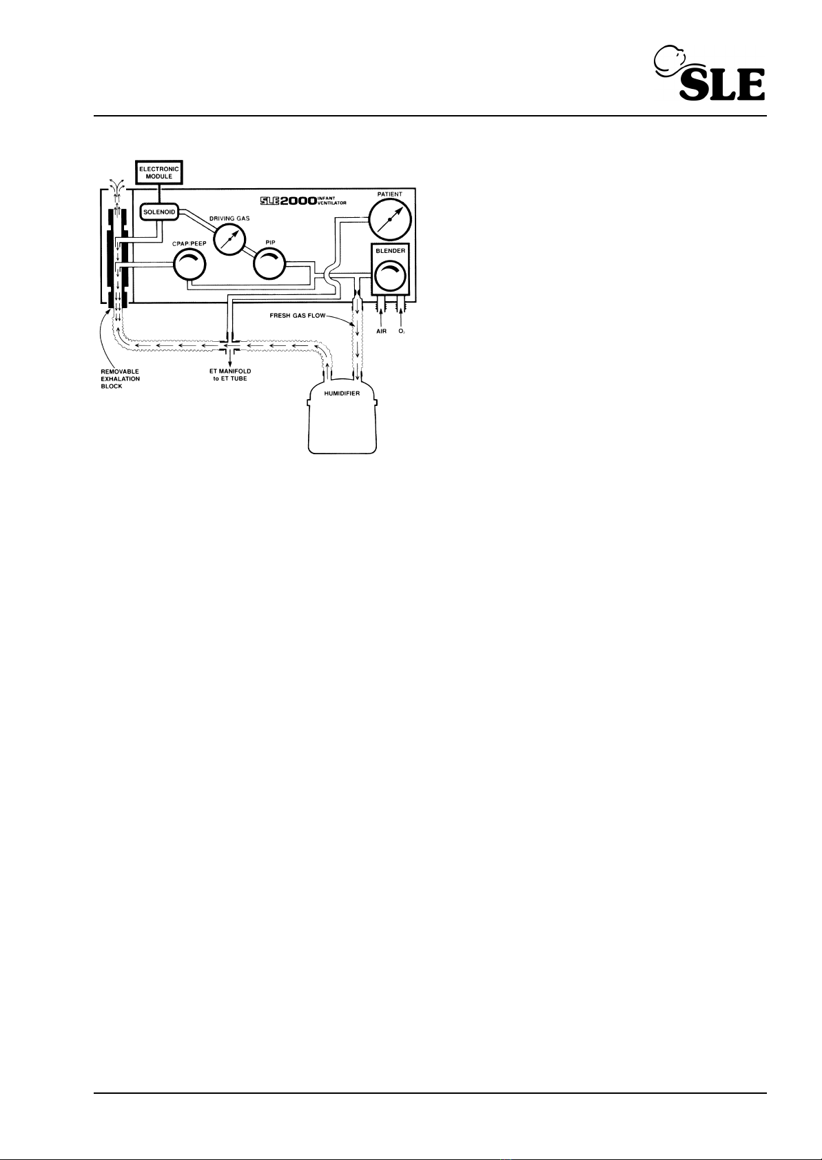
2. Principles of operation SLE2000 valveless system*
The patient circuit is supplied with a constant fixed flow of 5LPM fresh gas. This gas comes
from the internally mounted oxygen blender and its concentration is also monitored by a fuel
cell and displayed on the FlO2 digital display. This fresh gas supply is then passed through a
humidifier to the inspiratory port of the patient ET connector. Built into the ventilator are
circuits to detect either a gas flow failure or a tubing blockage. The patient circuit requires a
restrictor fitted into the inspiritory port. Therefore, only SLE approved patient circuits must
be used.
The Expiratory limb of the patient circuit is connected to the Exhalation port on the ventilator.
This consists of a removable block mounted on a manifold, accessed by lowering the left
hand side cover. The expiratory manifold has two nozzles. The front one to generate CPAP/
PEEP and is supplied via the CPAP regulator on the front panel of the Pneumatic Module.
The rear one to generate peak inspiratory pressure(PIP).
To avoid the possibility of gas dilution these regulators are supplied with the same oxygen
concentration as the Fresh Gas supply . The front nozzle is used to generate an opposing
flow to the Fresh Gas in the exhalation block and thus create CPAP The rear nozzle is used
to generate the peak inspiratory pressure in the same way, supplying constant pressures at
all breathing rates.
(SLE2000) Page 9
The PIP regulator and gauge on the front
panel set the pressure that is supplied to a
solenoid valve which is connected to the rear
nozzle.
The Electronic Module controls the rate and
duration of the flow of Driving Gas into the
Exhalation block in opposition to the Fresh
Gas flow. This opposing flow acts as a
pneumatic piston and creates a pressure
wave at the ET manifold. The lung inflation
pressure and hence the tidal volume are
controlled by the PIP regulator.
NOTE: The ventilator should be set to a
square waveform for breathing rates above 60 BPM
* The Valveless Ventilation Principle was designed and patented by Prof. J G Whitwam and Mr. M. K.
Chakrabarti of the R.P.G.M.S Hammersmith Hospital.
This patent is exclusively licensed to SLE

Page 10 (SLE2000)
3. User/owner responsibility
This SLE 2000 INFANT VENTILATOR equipment and the authorised accessories for it are
designed to function as specified in the relevant instruction manual only when operated,
maintained and repaired in accordance with supplied manuals and instructions. This
equipment must be periodically checked, recalibrated, maintained and components repaired
and replaced when necessary for the equipment to operate safely and reliably. Parts that
have failed, in whole or in part, or exhibit excessive wear, or are contaminated, or are
otherwise at the end of their useful life should not be used and should be replaced
immediately with parts supplied by SLE or parts which are otherwise approved by SLE.
Equipment which is not functioning correctly or is otherwise in need of repair or maintenance
must not be used until all necessary repairs and/or maintenance have been completed and
a factory authorised service representative has certified that the equipment is fit and ready
for use. This equipment and any of its accessories or component parts should not be
modified.
The owner/user of this equipment shall have the sole responsibility and liability for any
damage or injury to persons or property (including the equipment itself) resulting from
operation not in accordance with the operating instructions, or from faulty maintenance not
in accordance with the authorised maintenance instructions, or from repair by anyone other
than a factory authorised service representative, or from unauthorised modification of the
equipment or accessories, or from the use of components or accessories that have either
been damaged or not authorised for use with this equipment by the factory.

(SLE2000) Page 11
4. Warnings
1 Oxygen - Clinical use. Oxygen is a drug and should be prescribed as such.
2 Oxygen - Fire Hazard. Oxygen vigorously supports combustion and its use requires
special precaution to avoid fire hazards. Keep all sources of ignition away when
oxygen is in use. Do Not use oil or grease on oxygen fittings or where oxygen is used.
3 The ventilator functional tests must be carried out each time the SLE 2000 is used on
patients. If any of these tests do not function as described then there is a problem and
the ventilator must not be used until it is rectified.
4 The humidifier used in the patient circuit must be operated and maintained in
accordance with its manufacturer’s instructions. It is the owners responsibility to
ensure that the equipment is regularly maintained.
5 Failure to comply with the recommended service programs could lead to injury to the
patient, operator or damage to the ventilator. It is the owners responsibility to ensure
that the equipment is regularly maintained.
6 Functioning of this ventilator may be adversely affected by high frequency surgical
(Diathermy) , defibrillators, mobile phones, short-wave therapy or equipment producing
strong magnetic fields, operating the in vicinity.
7 The Ventilator must be plugged into a suitably rated and grounded electrical power
source.
8 There is no special protection provided against ingress of water or liquids.
9 The equipment is not suitable for use with, or in the presence of flammable anaesthetic
mixtures.
10 Use only SLE approved patient circuits. On no account should antistatic or electrically
conductive tubing be used in the patient circuit.
11 No external voltage should be applied to the auxiliary socket. Any connections to this
socket must be approved by SLE and screened to comply with EMC regulations.
Ensure protection cap is fitted when socket is not in use.
12 The electronic module of the ventilator contains a primary battery for mains failure
alarm, if the ventilator is not to be used for 3 months or more, then the battery should
be removed.
13 Care should be taken when attaching other equipment as this may affect stability.
14 If the SLE 2000 Infant Ventilator is adversely affected by equipment emitting
electromagnetic interference then that equipment should be switched off or removed
from the vicinity of the 2000. Conversely, if the 2000 is the source of such interference
to neighbouring equipment then it should be switched off or taken to another location.

Page 12 (SLE2000)
5. Symbols used on or in the equipment
Protective Earth
Attention, Consult accompanying documents.
B.S.I. and I.E.C. symbol for equipment with type B (non isolated parts).
Do not dispose of as general waste (WEEE directive).
(Appears on serial number label).
WARNING : - No external voltage should be applied to the auxiliary socket.
WARNING : - The electronic module contains a primary battery. If the unit is
not to be used for a period exceeding 3 months, it is recommended that the
battery be removed.
Mains
Fuses
Two externally accessible fuses are;
Type T 0.2 amps. For 200 - 250V
Type T 0.5 amps. For 100 - 120V

(SLE2000) Page 13
6. Glossary of abbreviations
amp ........................ Ampere
BPM ....................... Breaths Per Minute
cm .......................... Centimetre
cmH2O ................... Centimetres of Water Pressure
CMV ....................... Continuous Mandatory Ventilation
CPAP ..................... Continuous Positive Airway Pressure
°C........................... Degrees Centigrade
°F ........................... Degrees Fahrenheit
DISS....................... Diameter Index Safety System
ETO........................ Ethylene Oxide
ET .......................... Endotracheal
Exp......................... Expiration Time
FIO2....................... Fractional concentration of Inspired Oxygen
Hz........................... Hertz
ID ........................... Internal Diameter
I:E........................... Inspiratory : Expiratory ratio
Insp ........................ Inspiration Time
IMV......................... Intermittent Mandatory Ventilation
MAP ....................... Mean Airway Pressure
IPPB....................... Intermittent Positive Pressure Breathing
IPPV....................... Intermittent Positive Pressure Ventilation
kg ........................... Kilogram
lb ............................ Pound
LPM........................ Litres per Minute
Peak....................... Peak Airway Pressure
ml ........................... Millilitre
O2........................... Oxygen
PEEP ..................... Positive End Expiratory Pressure
PSI ......................... Pounds per Squire Inch
psig ........................ Pounds per Squire Inch Gauge
SIMV ...................... Synchronous Intermittent Mandatory Ventilation
VAC........................ Volts, Alternating Current
Vt............................ Tidal Volume
Nist......................... Non interchangable Standard Terminal
PTV ........................ Patient Triggered Ventilation
PIP ......................... Peak Inspiratory Pressure
ms .......................... Millisecond

Page 14 (SLE2000)
This page is intentionally blank.

(SLE2000) Page 15
Ventilator Control Description

Page 16 (SLE2000)
7. Ventilator control description
The SLE 2000 consists of two linked modules, Electronic and Pneumatic.
7.1 Front Panel
Electronic
Module
Pneumatic
Module
28
1
23457912
13
14
17
18
19
20
21
22
24
25
26
10
27
6811
15
23
16

(SLE2000) Page 17
7.2 Function of front panel controls and indicators
Nº Item Description
1 POWER and
OPERATIONAL
MODE Switch
Selects Power OFF, ALARM TEST/CPAP, CMV,
PTV, SIMV modes.
2 POWER LED Indicates power is ‘ON’.
3 SYSTEM FAIL LED When this LED lights and the alarm sounds, it
indicates failure of the main processor. If this
happens, the ventilator must be removed from
service.
4 BPM digital display
with adjustment
knob
Displays between 1-250 BPM.
Available in two ranges: 1-125 BPM& 126-250
BPM, selectable by rear security key switch
5INSP.TIMEdigital
display with
adjustment knob
Inspiratory Time
Displays 0.1-3.0 seconds in 1-125 BPM range
or 0.01-0.3 seconds in 126-250 BPM range.
6 FRESH GAS
BLOCK audible
alarm.
Indicates problems within the patient circuit line.
7 I:E RATIO digital
display
Displays from 9.9:1 to 1:9.9 calculated from BPM
and insp. time
8 LEAK LED’s
audible alarm.
Indicates problems within the patient circuit line.
9 MAX MEAN MIN
switch with digital
PRESSURE display
Selects and displays Max., Mean or Min airway
pressures.
10 FIO2digital display Accurately displays the % O2as set by the Air-
Oxygen Blender.
11 TRIGGER BACK-
UP LED
Indicates a machine-delivered breath due to patient
failure to trigger ventilate or during back-up time
window.
12 MANUAL BREATH
Pushbutton
Causes delivery of a single breath in CPAP, CMV
and PTV modes to preset inspiration times and
pressures.
13 Pressure Gauge -6
to +60 cmH2O.
Proximal Airway Pressure. This pressure is
displayed more accurately by the independent
digital display.
14 PTV SENSITIVITY
control
Variable patient trigger level setting.
Sensitivity between 1(least sensitive to patient
effort) and 5 (most sensitive to patient effort).

Page 18 (SLE2000)
15 PRESSURE WAVE
switch
Permits change of leading edge of pressure wave
from square to taper in 1-125 BPM range only.
16 ALARM MUTE
Pushbutton and
LED
Mutes audible alarms for one minute.
17 AIR OXYGEN
BLENDER control
Sets air/oxygen mix between 21 and 100% 02±
3%
with digital indication from independent monitoring
circuits.
18 O2inlet O2 hose connector.
19 Medical air inlet Medical air hose connector.
20 Inspiratory
Pressure
Regulator
Adjusts driving pressure to set circuit inspiratory
pressure.
Range 0-60 cmH2O.
21 SYSTEM DRIVING
PRESSURE gauge
Approximate indication of the pressure above
PEEP which will be delivered to the patient in CMV,
PTV, SIMV or manual breath modes.
22 CPAP/PEEP
regulator
Sets CPAP level in the circuit, range is 0 to 15
cmH2O (nominal).
23 ALARM RESET
Pushbutton
Resets audible and visual alarms.
24 Fresh Gas Port 5LPM blended gas supply to patient (ventilator
powered up).
1LPM blended gas supply to patient (ventilator
OFF)
25 Proximal airway Proximal airway tube connector.
26 Exhalation block Connection for expiratory limb of patient circuit.
27 PIP, CYCLE FAIL
and HIGH alarm
LED’s with control
Sets visual and audible alarm level for inspiratory
pressure between 0 and 60 cmH2O.
28 CPAP Alarm LED
and control
Sets visual and audible alarm level for CPAP
pressure.
Nº Item Description
(SLE2000) Page 19
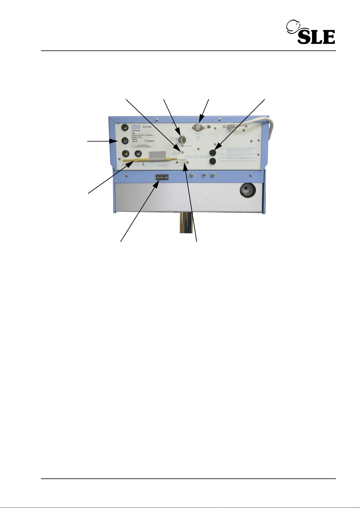
7.3 Rear panel
Nº Item
1FIO
2calibration adjustment.
2 125 - 250 BPM range switch
3 Aux. Output socket.
4 Fuse Holders
5 Optional serial port
6 Running Time Indicator
7FIO
2adjustment tool.
8 Alarm sounder
7
3
6
2
5
4
1
8

Page 20 (SLE2000)
7.4 Side panel
Nº Item
1 Side flap latching mechanism.
2 Fixed jet.
3 Expiratory tube guide.
3
2
1
Other manuals for SLE2000 HFO
2
Table of contents
Other SLE Medical Equipment manuals


