TABLE OF CONTENTS
OVERVIEW....................................................................................................................................... 3
BASIC OPERATION.......................................................................................................................... 4
Sensor Operation..................................................................................................................................................... 4
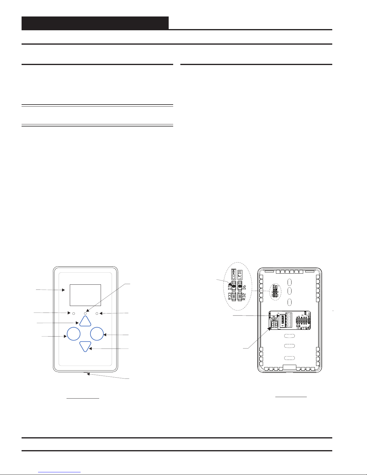
LED Operation ......................................................................................................................................................... 4
MOUNTING AND WIRING ................................................................................................................ 5
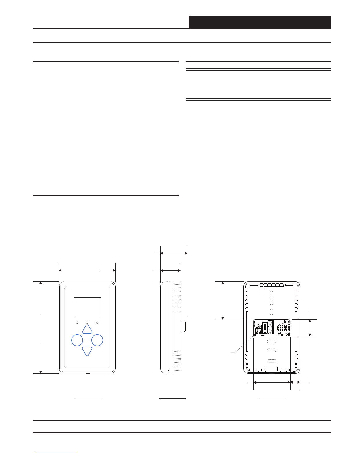
Dimensions .............................................................................................................................................................. 5
Environmental Requirements................................................................................................................................... 5
Important Wiring Considerations.............................................................................................................................. 5
Mounting .................................................................................................................................................................. 5
SENSOR OPERATION ...................................................................................................................... 6
Main Sensor Display Screens....................................................................................................6
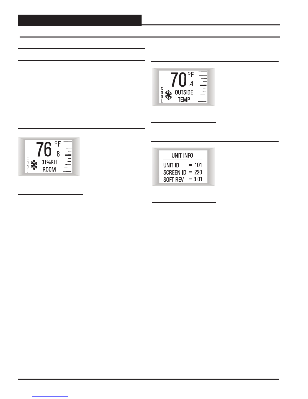
Temperature and Humidity Status Screen .......................................................................................................... 6
Outside Air Temperature Humidity Status Screen............................................................................................... 6
Unit Information Screen ...................................................................................................................................... 6
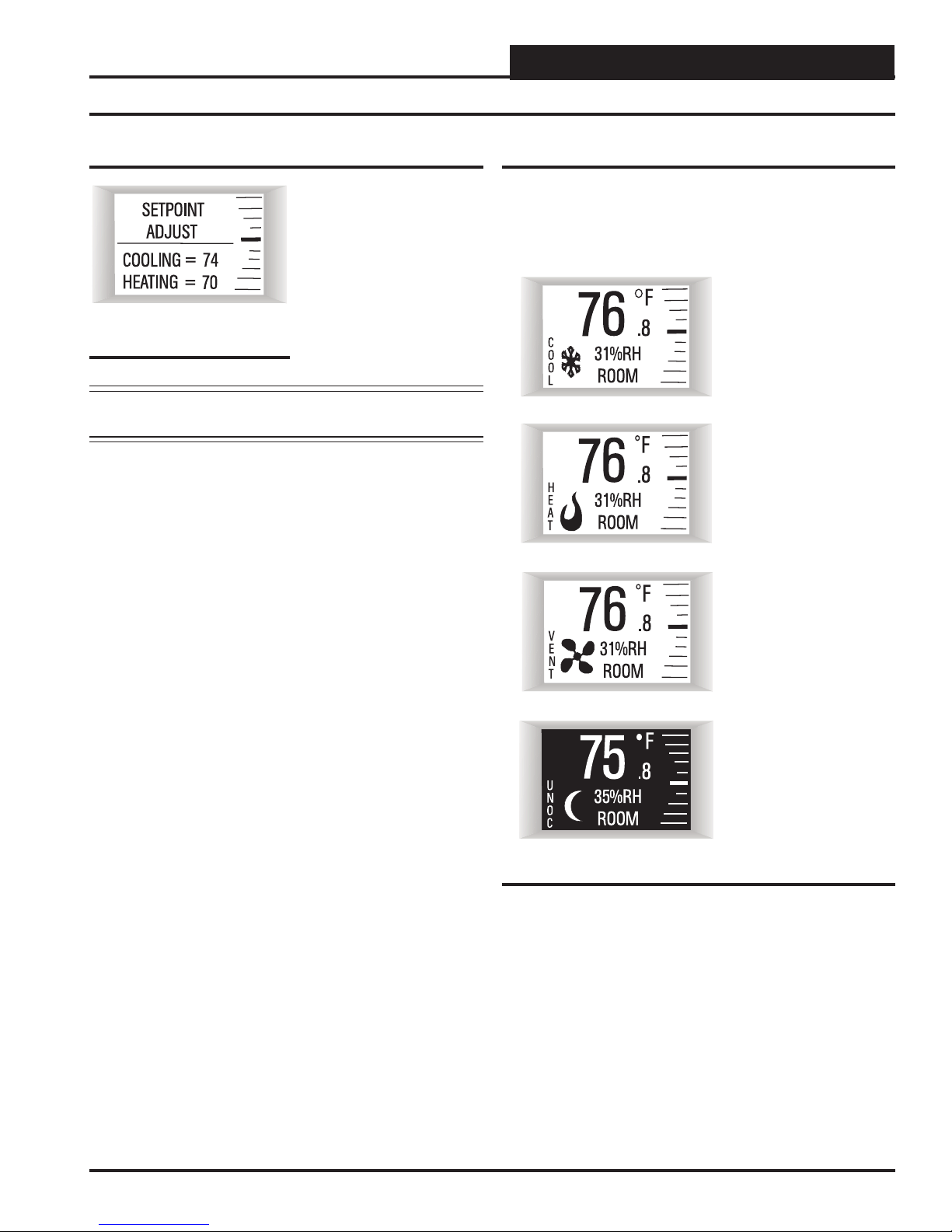
Setpoint Adjust Screen ....................................................................................................................................... 7
Operation Modes ................................................................................................................................................ 7
TROUBLESHOOTING....................................................................................................................... 8
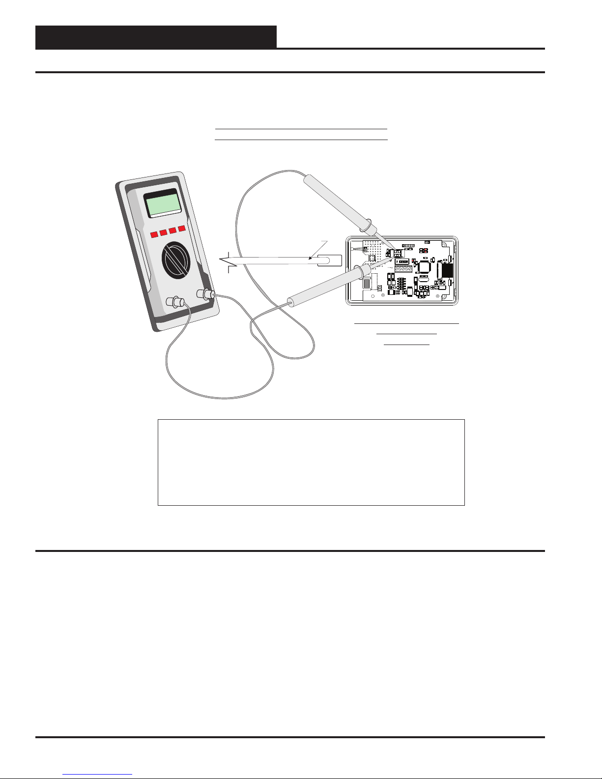
Temperature Sensor Testing for the OE217-02 Temperature Only Sensor.............................................................. 8
Temperature / Resistance Chart .............................................................................................................................. 9
APPENDIX ..................................................................................................................................... 10
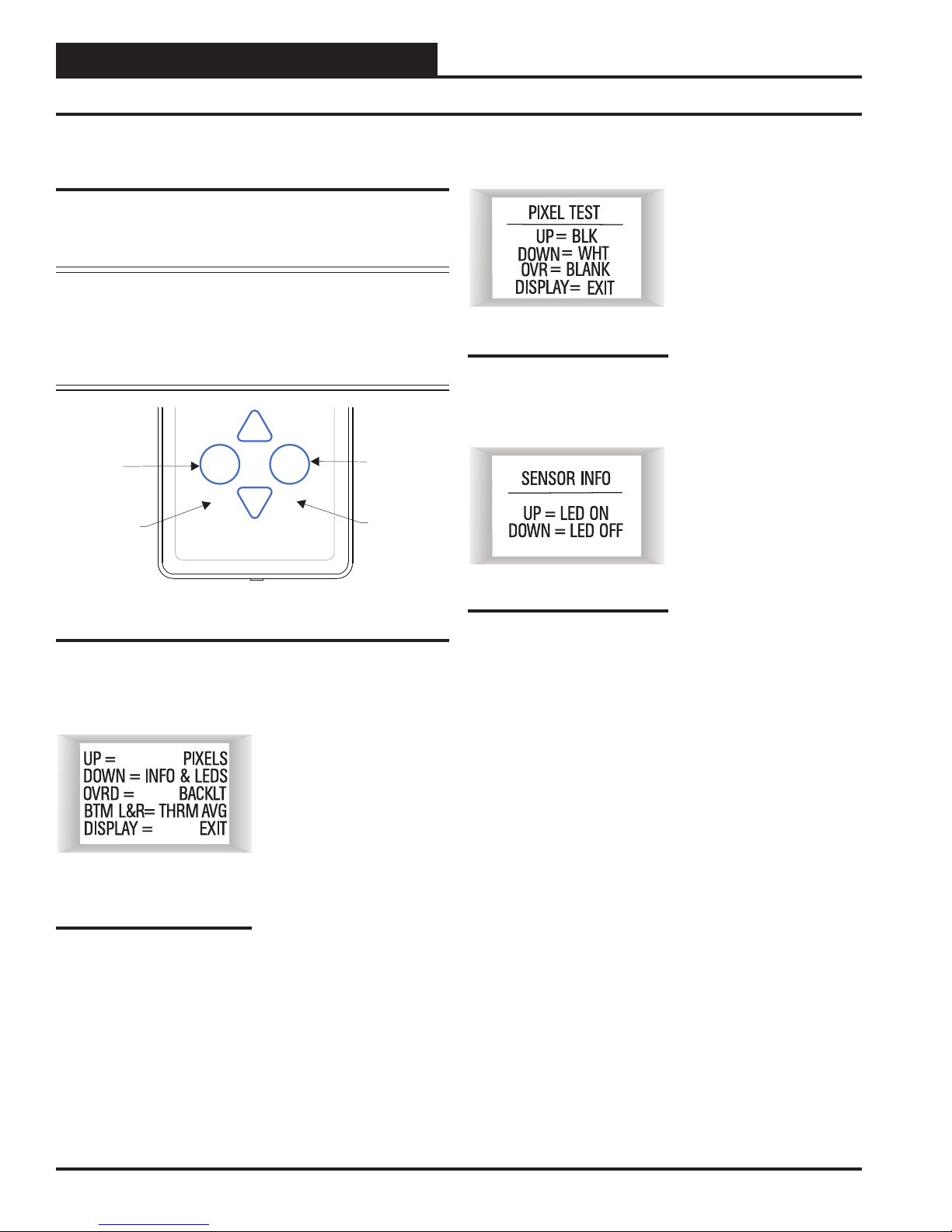
Sensor Configuration and Test Screens ................................................................................................................ 10
Connecting the Digital Room Sensor to the HVAC Unit Controller ........................................................................ 12
Connecting a Wall Mounted E-BUS CO2Sensor to the HVAC Unit Controller ...................................................... 13
Connecting a Remote Sensor................................................................................................................................ 14
Mounting Plate Dimensions ................................................................................................................................... 17
WattMaster Controls Inc.
8500 NW River Park Drive · Parkville, MO 64152
Toll Free Phone: 866-918-1100
PH: (816) 505-1100 · FAX: (816) 505-1101 ·
E-mail: mail@wattmaster.com
Visit our web site at www.orioncontrols.com
WattMaster Form: AA-EBUS-DRS-TGD-01K
AAON®Manual Part Number: V08370
AAON®is a registered trademark of AAON, Inc., Tulsa, OK.
Neither WattMaster Controls, Inc. nor AAON®assumes any respon-
sibility for errors or omissions in this document.
This document is subject to change without notice.
All rights reserved. © November 2017 WattMaster Controls, Inc.
www.aaon.com
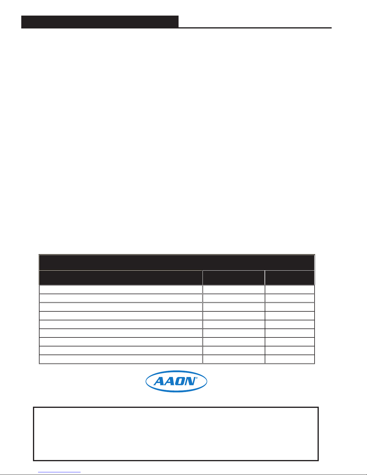
PART NUMBER CROSS REFERENCE TABLE
PART DESCRIPTION ORION AAON TULSA
E-BUS LCD Digital Room Sensor Temp Only OE217-02 V09290
E-BUS LCD Room Sensor Temp & Humidity OE217-03 V09300
E-BUS Digital Room Sensor Temp & Humidity (No LCD Display) OE217-04 V12920
Mounting Plate BK000081 N/A
E-BUS CO2Sensor OE256-05 V09310
Return Air Temperature Sensor OE231 R44940 / P87140
EBC E-BUS Cables - varying lengths EBC-XXXF N/A
VCCX2 Controller OE338-26B-VCCX2 V87900
VCB-X Controller OE335-26B-VCBX V28940