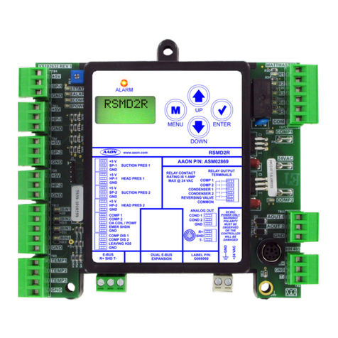
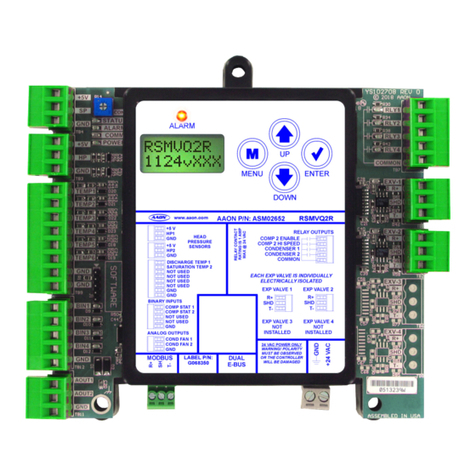
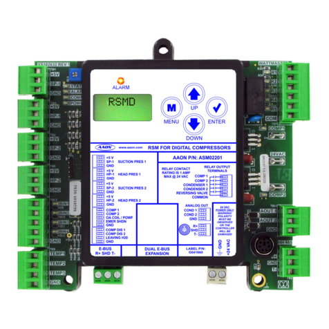
AAON RSMVQ Quick start guide

RSMVQ
Technical Guide

AAON
2425 South Yukon Ave.
Tulsa, OK 74107-2728
www.aaon.com
Factory Technical Support Phone: 918-382-6450
AAON®Controls Support: 866-918-1100
It is the intent of AAON®to provide accurate and current product
information. However, in the interest of product improvement,
AAON® reserves the right to change pricing, specications, and/
or design of its product without notice, obligation, or liability.
AAON® P/N: G079110, Rev B
Copyright August 2021 AAON, Inc.
AAON®is a registered trademark of AAON, Inc., Tulsa, OK.
Copeland Scroll™ is a registered trademark of Emerson
Electric Co., Sidney, OH
Danfoss VFD® is a registered trademark of Danfoss A/S,
Tallahassee, FL
DMQ®is a registered trademark of DunAn Microstaq, Inc.
of Austin, TX.
RSMVQ REVISION LOG
REVISION AND DATE CHANGE
Rev. A, April 12, 2021 Original
Rev. B, August 18, 2021 Formatting and Guide updates
www.aaon.com
RSMVQ PARTS REFERENCE
PART DESCRIPTION PART NUMBER
RSMVQ ASM02293
VCCX2 Controller ASM01698
Prism 2 ASM02533
IP Module Kit ASM01902
CommLink 5 ASM01874
E-BUS Cable Assembly 1.5 ft., 3 ft., 10 ft., 25 ft., 50 ft., 75 ft.,
100 ft., 150 ft., 250 ft., and 1000 ft. spool
G029440 (1.5 ft.), G012870 (3 ft.), G029460 (10 ft.), G045270 (25 ft.),
G029510 (50 ft.), G029530 (75 ft.), G029450 (100 ft.), G029470 (150 ft.),
V36590 (250 ft.), G018870 (SPOOL)
Modular Service Tool SD - Operator Interface ASM01895
All manuals are also available for download from
www.aaon.com/controlsmanuals

3RSMVQ Technical Guide
TABLE OF CONTENTS
OVERVIEW....................................................................................................................... 5
RSMVQ Overview................................................................................................................................................... 5
RSMVQ Dimensions ............................................................................................................................................... 6
INSTALLATION AND WIRING......................................................................................... 7
Electrical and Environmental Requirements ........................................................................................................... 7
WIRING ............................................................................................................................ 8
RSMVQ Inputs Wiring............................................................................................................................................. 8
RSMVQ Outputs Wiring .......................................................................................................................................... 9
INPUTS AND OUTPUTS................................................................................................ 10
RSMVQ Module Inputs/Outputs Map.................................................................................................................... 10
RSMVQ Inputs and Outputs .................................................................................................................................11
SEQUENCE OF OPERATIONS....................................................................................... 12
Cooling Mode and Dehumidication Operation .................................................................................................... 12
Envelope Protection.............................................................................................................................................. 13
Electronic Expansion Valve Operation and Head Pressure Control ..................................................................... 14
LCD SCREENS ............................................................................................................... 15
LCD Display Screen and Navigation Keys............................................................................................................ 15
Main Screens Map ................................................................................................................................................ 16
Module Screens .................................................................................................................................................... 17
System Status Screens......................................................................................................................................... 18
Sensor Status Screens ......................................................................................................................................... 19
Alarms Screens..................................................................................................................................................... 20
Alarm History Screens .......................................................................................................................................... 21
Setpoint Status Screens ....................................................................................................................................... 22
Copeland™ Packaged VFD Screens.................................................................................................................... 23
Danfoss VFD Screens .......................................................................................................................................... 24
Danfoss VFD Screens .......................................................................................................................................... 25
Copeland™ VFD Screens..................................................................................................................................... 26
Copeland™ VFD Screens and DMQ EXV Screens.............................................................................................. 27
TROUBLESHOOTING .................................................................................................... 28
LED Diagnostics ................................................................................................................................................... 28
Temperature Sensor Testing ................................................................................................................................. 29
Head Pressure Transducer ................................................................................................................................... 30
APPENDIX A: SYSTEM CONFIGURATION ................................................................... 31
Single Condenser Per Module ............................................................................................................................. 31
Two Condensers Per Module................................................................................................................................ 32
Compressor Type Selection .................................................................................................................................. 33
Unit Tonnage Selection and Compressor Type Specication Table...................................................................... 34
NOTES............................................................................................................................ 35

4RSMVQ Technical Guide
FIGURES AND TABLES
TABLES
Table 1: RSMVQ Electrical and Environmental Requirements .........................................................................................7
Table 2: RSMVQ Inputs and Outputs .................................................................................................................................10
Table 3: Compressor Speed/Head Pressure......................................................................................................................14
Table 4: Navigation Key Functions.......................................................................................................................................15
Table 5: Editing Key Functions .............................................................................................................................................15
Table 6: 0-5V Temperature Sensor - Voltage and Resistance for Type III Sensors .....................................................29
Table 7: Head Pressure Transducer Chart .........................................................................................................................30
Table 8: Compressor Type Specication Table ..................................................................................................................34
FIGURES
Figure 1: RSMVQ Dimensions ................................................................................................................................................6
Figure 2: RSMVQ Inputs Wiring...............................................................................................................................................8
Figure 3: RSMVQ Outputs Wiring............................................................................................................................................9
Figure 4: Danfoss®VZH028, VZH035, VZH044 Envelope ...............................................................................................13
Figure 5: Danfoss VZH052 and VZH065 Envelope ............................................................................................................13
Figure 6: Copeland™ ZPV0662E Envelope .......................................................................................................................13
Figure 7: Copeland™ ZPV0962E Envelope.........................................................................................................................13
Figure 8: LCD Display and Navigation Keys........................................................................................................................15
Figure 9: RSMVQ LED Locations ..........................................................................................................................................28
Figure 10: Prism 2 - Single Condenser Module Conguration............................................................................................31
Figure 11: Prism 2 - Two Condensers Module Conguration..............................................................................................32
Figure 12: RSMVQ Module A Compressor Type ...................................................................................................................33
Figure 13: Miscellaneous Setpoints Screen - Copeland™ Model Selection.....................................................................33
Figure 14: Update Copeland™.................................................................................................................................................33
Figure 15: RSMVQ Unit Tonnage Selection ...........................................................................................................................34

5RSMVQ Technical Guide
OVERVIEW
RSMVQ Overview
RSMVQ Features and Applications
The Refrigerant System Module for VFD compressors with
DMQ®Universal Superheat Control/Sensor (RSMVQ) monitors
and controls one or two refrigeration circuits of the AAON unit. It
is used in conjunction with the VCCX2 Controller. The RSMVQ
module is designed for R410-A refrigerant.
The RSMVQ is for units with the following congurations:
1. One or two circuits with no reheat, reheat on the rst
circuit if one circuit, or reheat on both circuits if two
circuits.
2. Must have one MODBUS-controlled VFD compressor
on the rst circuit.
3. Must have a xed or two-step compressor on the
second circuit.
4. Must have at least one DMQ® Electronic Expansion
Valve (EXV).
Optional congurations include:
1. A single condenser fan output signal for two circuits
or one condenser fan output signal per circuit.
2. Single or dual EXVs.
In addition, the RSMVQ cannot be used in a heat pump
application (air-to-air or water-source) and cannot have multiple
RSM modules.
The RSMVQ uses an E-BUS cable to connect to the VCCX2
Controller. Only one RSMVQ can be connected. There are two
E-BUS expansion ports which allow connection to the VCCX2
Controller, communicating sensors, and other E-BUS modules.
The RSMVQ is congured using Prism 2 software.
The RSMVQ provides four analog inputs, two binary inputs,
four relays, and two analog outputs. See Figures 2 and 3, pages
8 and 9, for wiring.
The RSMVQ provides the following:
• Modulates the compressors or controls staging to
satisfy the Suction Coil (Saturated) Temperature.
The Suction Coil (Saturated) Temperature Setpoint
is reset by the VCCX2 Controller to maintain the
Supply Air Temperature during Cooling Mode. During
Dehumidication Mode, it controls the compressors to
the Suction (Saturation) Temperature Setpoint.
• Modulates the condenser fan(s) to maintain the Head
Pressure Setpoint.
• Monitors the performance of the Superheat Controller
to maintain the Superheat Setpoint of each evaporator
coil.
• Provides alarms and safeties for the compressor and
condenser operation.
• Provides a 2 x 8 LCD character display and four buttons
that allow for status of system operation, system
setpoints, system congurations, sensors, alarms, and
to change the module’s address, if necessary.

6RSMVQ Technical Guide
OVERVIEW
RSMVQ Dimensions
Figure 1: RSMVQ Dimensions
6.10
2.05 2.05
4.10
5.61 4.98
AAON P/N: ASM02293
+24 VAC
GND
RELAY CONTACT
RATING IS 1 AMP
MAX @ 24 VAC
CONDENSER 1
COMP2ENABLE
COMP 2 HI SPEED
ANALOG OUTPUTS
COMMON
RELAY OUTPUTS
LABEL P/N:
G079120
COND FAN 1
COND FAN 2
GND
24 VAC POWER ONLY
WARNING! POLARITY
MUST BE OBSERVED
OR THE CONTROLLER
WILL BE DAMAGED
CONDENSER 2
+5 V
DISCHARGE TEMP1
COMP STAT 1
H1P
SATURATION TEMP2
COMP STAT 2
GND
NOT USED
GND
NOT USED
GND
BINARYINPUTS
MODBUS
RSMVQ
www.aaon.com
HEAD
PRESSURE
SENSORS
DUAL
E-BUS
EXP VALVE1
+5 V
H2P
GND
NOT USED
NOT USED
GND
NOT USED EXP VALVE2
R+
T-
SH
SHD
T-
R+
SHD
T-
R+
EXP VALVE3
NOT
INSTALLED
EXP VALVE4
NOT
INSTALLED
EACH EXP VA LVE IS INDIVIDUALLY
ELECTRICALLYISOLATED
NOT USED
ALARM
UP
DOWN
ENTERMENU
Note: All dimensions are in inches.

7RSMVQ Technical Guide
Control
Device
Voltage
VA Load
Operating
Temperature
Humidity
(Non-
Condensing)
RSMVQ
18-30 VAC 18 -22°F to 158°F
-30ºC to 70ºC 0-95% RH
Inputs
Resistive Inputs require 10KΩ
Type III Thermistor
24 VAC Inputs provide
4.7KΩ Load
Outputs Relay Outputs: 1 amp
maximum per output.
INSTALLATION AND WIRING
Electrical and Environmental Requirements
General
Correct wiring of the AAON unit controller and its modules is
the most important factor in the overall success of the installation
process. TheAAON unit controller and modules are installed and
wired at the AAON factory. Some of the following information
may not apply to your installation if it was pre-wired at the
factory. However, if troubleshooting of the controller or modules
is required, it is a good idea to be familiar with the system wiring.
Wiring
The modules must be connected to an 18-30 VAC power source
of the proper size for the calculated VA load requirements. All
transformer sizing should be based on the VA ratings listed in
Table 1, this page.
NOTE: If the temperature at the controller is below -4ºF
(-20ºC), the display refresh rate could be less
responsive.
WARNING: When using a single transformer to power
more than one controller or expansion
module, the correct polarity must always
be maintained between the boards. Failure
to observe correct polarity will result
in damage to the AAON unit controller,
RSMVQ, and any associated module.
Please carefully read and apply the following information when
wiring the unit controller, RSMVQ, and any associated module.
1. All wiring is to be in accordance with local and
national electrical codes and specications.
2. All 24 VAC wiring must be connected so that all
ground wires remain common. Failure to follow this
procedure can result in damage to the controller and
connected devices.
3. Minimum wire size for 24 VAC wiring should be
18-gauge.
4. Minimum wire size for all sensors should be 24-gauge.
Some sensors require two-conductor wire and some
require three-or four-conductor wire.
5. Minimum wire size for 24 VAC thermostat wiring
should be 22-gauge.
6. Be sure all wiring connections are properly inserted
and tightened into the terminal blocks. Do not allow
wire strands to stick out and touch adjoining terminals
which could potentially cause a short circuit.
7. When communication wiring is used to interconnect
AAON unit controllers together or to connect to other
communication devices, all wiring must be plenum-
rated, minimum 18-gauge, two-conductor, twisted pair
with shield. AAON can supply communication wire
that meets this specication and is color coded for
the network or local loop. Please consult your AAON
distributor for information. If desired, Belden #82760
or equivalent wire may also be used.
8. Before applying power to the AAON unit controller,
RSMVQ Modules, and any associated modules,
be sure to recheck all wiring connections and
terminations thoroughly.
Powering Up
When the controller and modules are rst powered up, the
POWER LED should light up and stay on continuously. If it
does not light up, check to be sure you have 24 VAC connected
to the controller, that the wiring connections are tight, and they
are wired for the correct polarity. The 24 VAC power must be
connected so all ground wires remain common. If after making
all these checks, the POWER LED does not light up, please
contact AAON Controls Support for assistance.
Table 1: RSMVQ Electrical and Environmental
Requirements
8RSMVQ Technical Guide
WIRING
RSMVQ Inputs Wiring
RSMVQ Wiring
The RSMVQ uses an E-BUS cable to connect to the VCCX2
Controller. Only one RSMVQ can be connected. There are two
E-BUS expansion ports which allow connection to the VCCX2
Controller, communicating sensors, and other E-BUS modules.
The RSMVQ uses four analog inputs, two binary inputs, four
relays, and two analog outputs. See Figure 2, this page, for inputs
wiring and Figure 3, page 9, for outputs wiring.
Head Pressure Control
The RSMVQ can monitor the Head Pressure Transducers and
control condenser fans to maintain a Head Pressure Setpoint. The
condenser fans will be controlled with a 0-10 VDC output signal.
Condenser and Compressor Conguration
Options
Please see pages 31-34 for condenser and compressor
conguration details.
WARNING: Observe polarity! All boards must be wired
with GND-to-GND and 24 VAC-to-24
VAC. Failure to observe polarity will result
in damage to one or more of the boards.
Expansion modules must be wired in such
a way that the expansion modules and the
controller are always powered together. Loss
of power to the expansion module will cause
the controller to become inoperative until
power is restored to the expansion module.
Figure 2: RSMVQ Inputs Wiring
18-30
VAC
GND
Line
Voltage
Size transformer for
correct total load.
RSMVQ = 18 VA
BK
RD
WH
COMP STAT 1
COMP STAT 2
COM
+
Condenser Fan 2
COM
+
Condenser Fan 1
BK
RD
WH
Head Pressure
Transducer
(by others)
Head Pressure
Transducer
(by others)
Discharge Temp
Sensor 1
Saturation Temp
Sensor 2
AAON P/N: ASM02293
+24 VAC
GND
RELAY CONTACT
RATING IS 1 AMP
MAX @ 24 VAC
CONDENSER 1
COMP 2 ENABLE
COMP 2 HI SPEED
ANALOG OUTPUTS
COMMON
RELAY OUTPUTS
LABEL P/N:
G079120
COND FAN 1
COND FAN 2
GND
24 VAC POWER ONLY
WARNING! POLARITY
MUST BE OBSERVED
OR THE CONTROLLER
WILL BE DAMAGED
CONDENSER 2
+5 V
DISCHARGE TEMP1
COMP STAT 1
H1P
SATURATION TEMP2
COMP STAT 2
GND
NOT USED
GND
NOT USED
GND
BINARY INPUTS
MODBUS
RSMVQ
www.aaon.com
HEAD
PRESSURE
SENSORS
DUAL
E-BUS
EXP VALVE1
+5 V
H2P
GND
NOT USED
NOT USED
GND
NOT USED EXP VALVE2
R+
T-
SH
SHD
T-
R+
SHD
T-
R+
EXP VALVE3
NOT
INSTALLED
EXP VALVE4
NOT
INSTALLED
EACH EXP VA LVE IS INDIVIDUALLY
ELECTRICALLY ISOLATED
NOT USED
ALARM
UP
DOWN
ENTERMENU

9RSMVQ Technical Guide
WIRING
RSMVQ Outputs Wiring
Figure 3: RSMVQ Outputs Wiring
18-30 VACGND
Line
Voltage
NOTE:
All relay outputs are normally open
and rated for 24 VAC power only,
1 amp maximum load.
COMPRESSOR 2 HI SPEED
COMPRESSOR 2 ENABLE
24 VAC ONLY
CONDENSER 1 ENABLE
Connect to
VCCX2
Controller
1
Copeland VFD
Drive Board
23
456
R+ to PIN 1
T- to PIN 4
SH to PIN 5
Superheat Controller’s
E-BUS Terminal
Superheat Controller’s
E-BUS Terminal
CONDENSER 2 ENABLE
Copeland
Packaged VFD Danfoss VFD
T- to Term 69
SH to Term 61
4561 2378
RS-485
Interface
69 68 61
Ground shield
wire on one end
4561 2378
4561 2378
R+ to Term 68
RED
GRN
BLK
RED
GRN
BLK
R+ to PIN 2
T- to PIN 7
SH to PIN 3
Ground shield
wire on one end
AAON P/N: ASM02293
+24 VAC
GND
RELAY CONTACT
RATING IS 1 AMP
MAX @ 24 VAC
CONDENSER 1
COMP 2 ENABLE
COMP 2 HI SPEED
ANALOG OUTPUTS
COMMON
RELAY OUTPUTS
LABEL P/N:
G079120
COND FAN 1
COND FAN 2
GND
24 VAC POWER ONLY
WARNING! POLARITY
MUST BE OBSERVED
OR THE CONTROLLER
WILL BE DAMAGED
CONDENSER 2
+5 V
DISCHARGE TEMP 1
COMP STAT 1
H1P
SATURATION TEMP 2
COMP STAT 2
GND
NOT USED
GND
NOT USED
GND
BINARYINPUTS
MODBUS
RSMVQ
www.aaon.com
HEAD
PRESSURE
SENSORS
DUAL
E-BUS
EXP VALVE1
+5 V
H2P
GND
NOT USED
NOT USED
GND
NOT USED EXP VALV E2
R+
T-
SH
SHD
T-
R+
SHD
T-
R+
EXP VALVE3
NOT
INSTALLED
EXP VALV E4
NOT
INSTALLED
EACH EXP VA LVE IS INDIVIDUALLY
ELECTRICALLY ISOLATED
NOT USED
ALARM
UP
DOWN
ENTERMENU

10 RSMVQ Technical Guide
INPUTS AND OUTPUTS
RSMVQ Module Inputs/Outputs Map
Inputs/Outputs Map
See Table 2, this page, for the RSMVQ inputs and outputs.
Table 2: RSMVQ Inputs and Outputs
REFRIGERATION SYSTEM MODULE
FOR VFD HEAT PUMP COMPRESSORS
Analog Inputs
1Head Pressure Transducer 1 (HP1)
2Head Pressure Transducer 2 (HP2)
3Discharge Temperature 1 (TEMP1)
4Saturation Temperature 2 (TEMP2)
Binary Inputs
1Compressor Status 1 (BI1)
2Compressor Status 2 (BI2)
Analog Outputs (0-10 VDC)
1Condenser Fan 1 (AO1)
2Condenser Fan 2 (AO2)
EXV COMM Ports
1Expansion Valve 1 (EXV-1)
2Expansion Valve 2 (EXV-2)
Binary Outputs (24 VAC)
1Compressor 2 Enable Relay (RLY1)
2Compressor 2 High Speed Relay (RLY2)
3Condenser 1 Enable Relay (RLY3)
4Condenser 2 Enable Relay (RLY4)
Communication Terminals
DUAL
E-BUS 2 E-BUS Ports
MODBUS MODBUS Communication Terminal Block

11RSMVQ Technical Guide
INPUTS AND OUTPUTS
RSMVQ Inputs and Outputs
+5 - VDC Power
This output is a 5 VDC output that supplies power to the Head
Pressure Transducer 1.
HP1 - Head Pressure Transducer 1
The Head Pressure Transducer is used to measure Head Pressure
at the discharge line. This Head Pressure is used to drive
Condenser Fan 1 to maintain a given Head Pressure Setpoint.
+5 - VDC Power
This output is a 5 VDC output that supplies power to the Head
Pressure Transducer 2.
HP2 - Head Pressure Transducer 2
The Head Pressure Transducer is used to measure Head Pressure
at the discharge line. This Head Pressure is used to drive
Condenser Fan 2 to maintain a given Head Pressure Setpoint.
TEMP1 - Discharge Temperature Sensor 1
This sensor is the Discharge Line Temperature Sensor for Circuit 1.
It is the G010470 Thermistor 10K ohm strap-on pipe sensor.
It is strapped to the discharge line immediately after the VFD
compressor and is used as a safety against high compressor
temperatures. Units with Copeland™VFDs have the Discharge
Line Temperature Sensor wired directly to the drive. Units with
Danfoss VFDs will have a Discharge Line Temperature Sensor
wired to TEMP 1 of the RSMVQ.
TEMP2 - Saturation Temperature Sensor 2
This sensor is the Suction Saturation Temperature Sensor for
Circuit 2. It is the G049490 Thermistor 10K strap-on pipe
sensor. It is strapped to the evaporator coil immediately after
the Thermal Expansion Valve (TXV) and is used to measure the
Suction Saturation Temperature of the second circuit.
BI1 - Compressor Status 1
A wet contact closure (24 VAC) on this input indicates
Compressor 1 is running. Typically, the source for this is a relay
output from the VCCX2. If BI1 opens, a compressor alarm will
be generated. Compressor 1 relay needs to be congured on the
VCCX2 as “A1 Compressor Run Status.”
BI2 - Compressor Status 2
A wet contact closure (24 VAC) on this input indicates
Compressor 2 is running. Typically, the source for this is a relay
output from the auxiliary contact on the compressor starter. If
BI2 opens, Compressor 2 Enable relay and Compressor 2 High
Speed Enable relay will de-energize and a compressor alarm
will be generated.
NOTE: The binary inputs require wet contacts (24 VAC
only) to recognize an active input. If you provide
dry contacts, the contact closure will not be
recognized.
AO1 - Condenser Fan 1 VFD Signal
This is a direct acting output signal that is used to modulate the
Condenser Fan 1 VFD (0-10 VDC signal) on an air cooled unit.
AO2 - Condenser Fan 2 VFD Signal
This is a direct acting output signal that is used to modulate the
Condenser Fan 2 VFD (0-10 VDC signal) on an air cooled unit.
EXV-1 - Electronic Expansion Valve
The EXV-1 is the communications port for EXV setpoints and
status communications.
EXV-2 - Electronic Expansion Valve
The EXV-2 is the communications port for EXV setpoints and
status communications.
RLY1 - Compressor 2 Enable
This relay turns on Compressor 2.
RLY2 - Compressor 2 High Speed Enable
This relay enables high speed on Compressor 2.
RLY3 - Condenser 1 Enable
This relay enables Condenser Fan 1.
RLY4 - Condenser 2 Enable
This relay enables Condenser Fan 2.

12 RSMVQ Technical Guide
SEQUENCE OF OPERATIONS
Cooling Mode and Dehumidication Operation
Cooling Mode Operation
Cooling Mode control staging is determined by the Supply Air
Temperature. Staging is met by turning the on/o compressor on
or o and the two-step compressor to low speed or high speed.
VFD compressor modulation is determined from Saturation
Temperature and Supply Air Temperature. If the Supply and
Saturation Temperatures are above their respective Setpoints,
the compressors will modulate up. If the Supply or Saturation
Temperatures are below their Setpoints, the compressors will
modulate down. Envelope and/or current protections also aect
the VFD compressor modulation.
Staging Up
1. If the Supply Air Temperature is above the Setpoint,
Compressor 1 VFD will turn on at the recommended
manufacturer’s speed for one minute. Compressor 1
VFD will modulate anytime thereafter if it is running.
2. If the Supply Air Temperature is above the setpoint
plus window, and Compressor 1 VFD is at 100% of its
capacity, Compressor 2 will turn on at low speed and
Compressor 1 will be reset to 67% of its range (min
to max). Compressor 1 VFD will modulate anytime
thereafter if it is running.
3. If the Supply Air Temperature remains above the
Setpoint plus window, and Compressor 1 VFD is at
100% of its capacity, Compressor 2 will be set to high
speed and Compressor 1 will be reset to 67% of its
range (min to max).
Staging Down
1. If the Supply Air Temperature is below the Setpoint
plus window and Compressor 1 VFD is at minimum
capacity, Compressor 2 will be set to low speed and
Compressor 1 will be reset to 67% of its range (min
to max).
2. If the Supply Air Temperature remains below the
Setpoint plus window, and Compressor 1 VFD is at
minimum capacity, Compressor 2 will be turned o
and Compressor 1 will be reset to 67% of its range
(min to max).
3. If the Supply Air Temperature continues to remain
below the Setpoint plus window, and Compressor 1
VFD is at minimum capacity, Compressor 1 will be
turned o.
4. If the Supply Air Temperature rises above the Setpoint
and Compressor 1 VFD’s minimum o time has been
met, Compressor 1 will be turned back on.
Dehumidication Operation
Dehumidication Mode control staging/modulation is determined
by using the lowest saturation temperature from each circuit.
Circuit 1 uses Superheat Controller Saturation Temperature and
Circuit 2 uses the Saturation Coil Temperature Sensor (Temp 2
input) mounted after the TXV.
Staging Up
1. Staging begins when the RSMVQ Module obtains the
Reheat Valve position and Reheat Supply Air Error
from the AAON unit controller. Compressor 1 VFD
will turn on at the manufacturer’s recommended
speed for one minute. Compressor 1 VFD will
modulate any time thereafter based on the Saturation
Temperature (lowest of both circuit’s readings).
2. If the Saturation Temperature (lowest of both
circuits’ readings) is above the Setpoint plus window,
Compressor 2 will turn on at low speed.
3. If the Saturation Temperature (lowest of both circuits’
readings) is above the Setpoint plus window, If the
Saturation Temperature of Circuit 2 is above the
Setpoint plus window, Compressor 1 VFD is at 67%
of its range min to max, the reheat valve is at 100%,
and the Supply Air Temperature is below the Reheat
Setpoint, Compressor 2 will be set to high speed.
Staging Down
1. If the Saturation Temperature of Circuit 2 is below the
Setpoint plus window, Compressor 1 VFD is below
50% (adjustable), and the reheat valve is below 50%,
Compressor 2 will be set to low speed.
2. If the Saturation Temperature of Circuit 1 is below
the Setpoint plus window and Compressor 1 VFD is
at minimum, Compressor 1 will be staged o.
NOTE: Compressor 2 cannot be turned off in
Dehumidication Mode unless failed on alarm
fault.

13RSMVQ Technical Guide
SEQUENCE OF OPERATIONS
Envelope Protection
Envelope Protection
The minimum operating speed reference is read from the VFD
and can change depending on where the compressor is operating
within its envelope.
The VFD compressor is set to 67% at any stage event. Therefore,
whenever a staging event occurs, the VFD compressor position
will be reset to the middle point of the modulation range. This
allows the compressor enough modulation time before making
another staging event to try to avoid cycling between staging
events.
Figure 4: Danfoss VZH028, VZH035, VZH044
Envelope
Figure 5: Danfoss VZH052 and VZH065 Envelope
Figure 6: Copeland™ ZPV0662E Envelope
Figure 7: Copeland™ ZPV0962E Envelope

14 RSMVQ Technical Guide
SEQUENCE OF OPERATIONS
Electronic Expansion Valve Operation and Head Pressure Control
Electronic Expansion Valve Operation
EXV operation is fully integrated into the Superheat Controller.
The Superheat Controller will measure suction pressure and
temperature to determine superheat and will automatically
modulate the EXV to maintain the congured superheat. The
RSMVQ will communicate with the Superheat Controller to set
the desired Superheat Setpoint and to retrieve operational data
for display and trending purposes.
Head Pressure Control
The RSMVQ can monitor a head pressure transducer and control
a condenser fan to maintain a Head Pressure Setpoint.
A condenser relay is commanded on when the rst compressor
is enabled. The condenser fan will be controlled with a 0-10
VDC output signal. When the condenser signal rst activates, it
maintains at 100% for 10 seconds.
In the Cooling Mode, the condenser signal will modulate to
maintain the Cooling Head Pressure Setpoint. The signal can
modulate between 15% and 100%. If the head pressure exceeds
550 psig, the condenser control signal will immediately go to
100% and a high head pressure alarm will be generated. The
alarm will be deactivated when the head pressure drops below
540 psig.
In the Dehumidication Mode, the Condenser Output Signal
controls to the Reheat Head Pressure Setpoint. High head
pressure conditions produce the same eects as in the Cooling
Mode.
If no head pressure sensor is detected, the Condenser Output
Signal will be maintained at 100%.
During condenser fan head pressure control, the Head Pressure
Setpoint will decrease when the VFD compressor speed
decreases. See Table 3, this page.
Compressor
Speed
Head Pressure Setpoint
(340 default - adjustable)
25% or lower 260 psig
25 - 100% 260 - 340 psig
100% 340 psig
Table 3: Compressor Speed/Head Pressure

15RSMVQ Technical Guide
LCD SCREENS
LCD Display Screen and Navigation Keys
LCD Display Screen and Navigation
Keys
The LCD display screens and buttons allow you to view status
and alarms, and enable force modes. See Figure 8, this page,
and refer to Table 4 and Table 5, this page, for key functions.
ALARM
UP
DOWN
ENTERMENU
Figure 8: LCD Display and Navigation Keys
Navigation
Key Key Function
MENU Use the MENU key to move through screens
within Main Menu categories and return to the
Main Menu while at other screens.
UP Use this key to adjust setpoints and change
congurations.
DOWN Use this key to adjust setpoints and change
congurations.
ENTER Use the ENTER key to navigate through the
Main Menu Screen categories.
Table 4: Navigation Key Functions
Table 5: Editing Key Functions
Editing
Key Key Function
UP
or
DOWN
Use the UP or DOWN key to enter Edit Mode on a
user-adjustable screen. Edit Mode is indicated by
the underscore appearing on the screen.
NOTE: Entering Edit Mode will also adjust the
value up one (UP key) or down one (DOWN key),
so you may have to readjust the value.
ENTER
Use the ENTER key to move through the digits
in the screen when editing a numeric value. An
extended press of the ENTER key saves your
edits no matter the location of the editing cursor
within the digits.
Press the ENTER key to save a non-numeric value
such as Hi Speed Network.
MENU
The MENU key cancels editing when in Edit Mode.
The screen you were editing will return to its
original value and the underscore will disappear.
A second press of the MENU key will return you
to the Main Menu.

16 RSMVQ Technical Guide
LCD SCREENS
Main Screens Map
RSMVQ Main Screens Map
Refer to the following map when navigating through the LCD
Main Screens. To scroll through the screens, press the <MENU>
button.
RSMVQ
1141vXXX
Press to scroll through REFRIG MODULE screens.
Press to go to SYSTEM STATUS screens.
SYSTEM
STATUS
Press to scroll through SYSTEM STATUS screens.
Press to go to SENSOR STATUS screens.
SENSOR
STATUS
Press to scroll through SENSOR STATUS screens.
Press to go to ALARMS screens.
ALARMS
Press to scroll through ALARMS screens.
Press to go to ALARM HISTORY screens.
ALARM
HISTORY
Press to scroll through ALARM HISTORY screens.
Press to go to SETPOINT STATUS screens.
SETPOINT
STATUS
Press to scroll through SETPOINT STATUS screens.
Press to go to VFD MENU screens.
Note: There are three separate VFD menus. The one that appears is
dependent on your unit’s conguration.
VFD
MENU
Press to scroll through VFD MENU screens.
Press to go to EXV TYPE screens.
EXV TYPE
DMQ
Press to scroll through EXV TYPE screens.

17RSMVQ Technical Guide
LCD SCREENS
Module Screens
RSMVQ Module Screens
Refer to the following map when navigating through the RSMVQ
Screens. From the RSMVQ MODULE Screen, press <ENTER>
to scroll through the screens.
RSMVQ
1141vXXX
E-BUS
+#
E-BUS COMMUNICATION DIAGNOSTICS
Number of COMM packets received.
SOFTWARE
1024vXXX
SOFTWARE VERSION
ADDRESS
#
CURRENT BOARD ADDRESS
SYS TYPE
COOL ONLY
CURRENT SYSTEM TYPE
COOL ONLY, or HEAT PUMP
#OF COMP
1 or 2
# OF COMPRESSORS
#OF EXVs
ISO-#
# OF EXPANSION MODULES
COMP A1=
FIXED OR MOD
COMPRESSOR 1 TYPE
COMP A2=
FIXED/TWO STEP
COMPRESSOR 2 TYPE
#OF COND
1 or 2
# OF CONDENSERS
TONNAGE
UNIT TONNAGE

18 RSMVQ Technical Guide
LCD SCREENS
System Status Screens
Refer to the following map when navigating through the System
Status Screens. From the SYSTEM STATUS Screen, press
<ENTER> to scroll through the screens.
SYSTEM
STATUS
MODE
SYSTEM MODE
MIN RUN, OFF, COOLING, HEATING, DEHUM, or FORCED
COMP A1
ON/OFF or
MODULATING %
COMPRESSOR 1
ON/OFF or MODULATING %
FIXED ON/OFF: Compressor is on or o.
MODULATING %: 0-100%
COMP A2
ON/OFF or HI
SPEED/LO SPEED
COMPRESSOR 2
ON, OFF, HI SPEED, or LO SPEED
FIXED ON/OFF: Compressor is on or o.
TWO STEP: High Speed or Low Speed
CONDFAN1
OFF
CONDENSER 1
COND FAN, NOT USED, or OFF
COND FAN MODULATING PERCENTAGE: 0-100%
CONDFAN2
OFF
CONDENSER 2
COND FAN, NOT USED, or OFF
COND FAN MODULATING PERCENTAGE: 0-100%
EXV A1
0%
EXV VALVE POSITION
0-100%
EXV 2
0% or NOT USED
EXV VALVE 2 POSITION
0-100% or NOT USED

19RSMVQ Technical Guide
LCD SCREENS
Sensor Status Screens
Refer to the following map when navigating through the Sensor
Status Screens. From the SENSOR STATUS Screen, press
<ENTER> to scroll through the screens.
SENSOR
STATUS
SUCTION
XXX PSIG
SUCTION PRESSURE READING FROM INPUT
HEAD PR1
XXX PSIG
HEAD PRESSURE 1 READING FROM INPUT
HEAD PR2
XXX PSIG
HEAD PRESSURE 2 READING FROM INPUT
SUPRHT 1
XX DEG
CURRENT SUPERHEAT 1 CALCULATION
SUPRHT 2
XX DEG
CURRENT SUPERHEAT 2 CALCULATION
DISCTEMP
XX DEG
DISCHARGE LINE TEMP 1 READING FROM INPUT
Only appears if congured for DANFOSS.
COIL 1
XX DEG
COIL TEMPERATURE 1
COIL 2
XX DEG
COIL TEMPERATURE 2
CALC CT
XX DEG
CALCULATED COIL TEMPERATURE
(Saturated Temperature)
SATCOIL2
XX DEG
SATURATION LINE: TEMP 2 READING FROM INPUT
Only appears if congured for two compressors/circuits.

20 RSMVQ Technical Guide
LCD SCREENS
Alarms Screens
Alarms Screen
If an alarm is present, the ALARM LED above the LCD display
will light up red and blink. The alarms will display and scroll
automatically from the ALARMS screen when alarms are present.
NO ALARMS: This will be shown if there are no current alarms.
DMQ NOT DETECTED: This will be shown if no communication
exists between the RSM and DMQ.
EBUS SLAVE (SLV) TIMEOUT: This alarm indicates that
communication has been lost between the RSMVQ and the
AAON controller. This can be the result of a bad cable, a missing
cable, or the module not being congured properly.
NO SUCTION PRESSURE TRANSDUCER (SUCT) DETECTED:
This alarm indicates the Suction Pressure Transducer is not
detected by the system. The system will shut down due to unsafe
suction safety and will retry after ve minutes.
NO HEAD PRESSURE TRANSDUCER (HEAD) DETECTED:
This alarm indicates the Head Pressure Transducer is not detected
by the system. This will cause the condenser to go to 100%.
COMPRESSOR (COMP) 1 FAULT: This alarm will occur if the
compressor fails to run 45 seconds after the relay is activated
or if the signal is lost after activation. This will cause an alarm
and will shut down the compressor (relay). The system will retry
after ve minutes.
COMPRESSOR (COMP) 2 FAULT: This alarm will occur if the
compressor fails to run 45 seconds after the relay is activated
or if the signal is lost after activation. This will cause an alarm
and will shut down the compressor (relay). The system will retry
after ve minutes.
HIGH HEAD PRESSURE (HP) DETECTED: This indicates a
High Head Pressure Alarm condition which is activated when
the Head Pressure rises above 550 psig. This will cause the
condenser to go to 100%.
LOW SUCTION PRESSURE FAILURE: This alarm will occur if
suction pressure stays below the Low Suction Pressure Setpoint
for one minute or falls below 40 psig for ve seconds. This
alarm will shut down the system. The system will retry after
ve minutes.
LOW SUCTION PRESSURE (SP) DETECTED: This alarm will
occur if suction pressure falls below the Low Suction Pressure
Setpoint for 20 seconds. The system will try to protect by
lowering compressor modulation percentage.
LOW SUPERHEAT 1 (SH1) DETECTED: This alarm will be
activated when the Superheat is less than 4ºF for two minutes
during normal operation or four minutes during the rst 10
minutes. The system will shut down and will retry after ve
minutes.
LOW SUPERHEAT 2 (SH2) DETECTED: This alarm will be
activated when the Superheat is less than 4ºF for two minutes
during normal operation or four minutes during the rst 10
minutes. The system will shut down. The system will shut down
and will retry after ve minutes.
COIL 1 TEMP 1 FAILURE: This alarm will occur if the coil
temperature is not within operable range (below -32ºF or above
310ºF). This could be the result of a bad sensor or faulty wiring.
This alarm will shut down the system. The system will reset after
ve minutes if the sensor is detected.
COIL 2 TEMP 2 FAILURE: This alarm will occur if the coil
temperature is not within operable range (below -32ºF or above
310ºF). This could be the result of a bad sensor or faulty wiring.
This alarm will shut down the system. The system will reset after
ve minutes if the sensor is detected.
COMP VFD FAULT: This alarm will occur if the Copeland™
VFD compressor communicates through E-BUS that it has shut
down due to a fault condition. The compressor module will
attempt to reset the fault after ve minutes if the compressor
sends the signal that it is okay to reset the fault.
LOH2OTMP—Low Leaving H2O Temp
NOH2OFLO—Proof of Water Flow
HIGH SUPERHEAT 1 (SH1) WARNING: If Superheat 1 is above
25ºF for two minutes, this alarm will appear on the module only.
It will not be sent to the main controller to display on Prism 2.
HIGH SUPERHEAT 2 (SH2) WARNING: If Superheat 2 is above
25ºF for two minutes, this alarm will appear on the module only.
It will not be sent to the main controller to display on Prism 2.
HIGH SUPERHEAT 1 (SH1) FAILURE: If Superheat 1 is above
30ºF for 10 minutes, it will turn o the compressors. It will retry
after ve minutes. If it fails twice in two hours, it will lock out
the compressors.
HIGH SUPERHEAT 2 (SH2) FAILURE: If Superheat 2 is above
30ºF for 10 minutes, it will turn o the compressors. It will retry
after ve minutes. If it fails twice in two hours, it will lock out
the compressors.
HIGH SUPERHEAT LOCKOUT: If the module fails on High
Superheat twice in two hours, it will lock out the compressors.
ALARMS
This manual suits for next models
1
Table of contents
Other AAON Control Unit manuals

AAON
AAON MODGAS-XWR2 Quick start guide

AAON
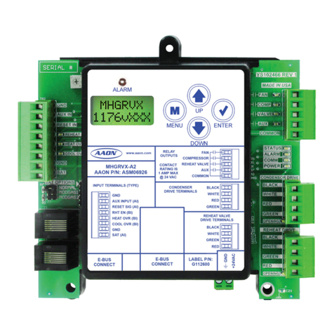
AAON MHGRVX-A2 Quick start guide

AAON
AAON RSM-DEV1 Quick start guide

AAON
AAON PREHEAT-X Quick start guide

AAON
AAON RSMD-CM Quick start guide

AAON
AAON MODGAS-XWR2-B Quick start guide

AAON
AAON HP2C2 Quick start guide

AAON
AAON RSMD2R Quick start guide

AAON
AAON RSMZ Quick start guide

AAON
AAON MODGAS-X Quick start guide
Popular Control Unit manuals by other brands

RF-Star
RF-Star RF-BM-ND04C manual

INAZUMA
INAZUMA WebCSA Series operating instructions

Bray Controls
Bray Controls STM Series installation instructions

Dungs
Dungs DGAI. 33F/2 Operation and assembly instructions

SolarEdge
SolarEdge ZigBee Plug-in installation guide

ABB
ABB Relion 670 series Commissioning manual