AAON MODGAS-XWR2-B Quick start guide

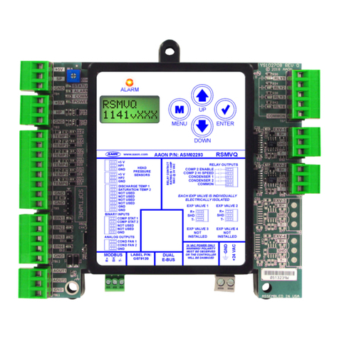
MODGAS-XWR2-B Module
Technical Guide

2MODGAS-XWR2-B Technical Guide
AAON
2425 South Yukon Ave.
Tulsa, OK 74107-2728
www.aaon.com
Factory Technical Support Phone: 918-382-6450
AAON Controls Support: 866-918-1100
It is the intent of AAON to provide accurate and current product
information. However, in the interest of product improvement,
AAON reserves the right to change pricing, specications, and/or
design of its product without notice, obligation, or liability.
AAON P/N: G112860, Rev. A
© July 2022 AAON Inc. All rights reserved.
AAON®is a registered trademark of AAON, Inc., Tulsa, OK.
White-Rogers®is a registered trademark of Emerson Climate
Technologies, Inc., St. Louis, MO
AAON assumes no responsibility for errors or omissions in
this document.
This document is subject to change without notice.
MODGAS-XWR2 PARTS REFERENCE
PART DESCRIPTION PART NUMBER
MODGAS-XWR2 Module ASM01695
MODGAS-XWR2-B Module ASM06909
12 Relay E-BUS Expansion Module ASM01873
VCCX2 Controller ASM01698
MHGRV-X Module ASM01670
MHGRV-X-A1 / MHGRV-X-B1 Module (no I2C) ASM07265 / ASM06910
MHGRV-X-A2 / MHGRV-X-B2 Module (no I2C, EBV05H Valve only) ASM06926 / ASM06927
Supply Air Temperature Sensor (6 in and 12 in.) G051240 (6 in.) and G051250 (12 in.)
MODGAS-XWR2 REVISION LOG
REVISION AND DATE
Rev. A, July 25, 2022 Original
www.aaon.com
All manuals are also available for download from
www.aaon.com/library

3MODGAS-XWR2-B Technical Guide
OVERVIEW ......................................................................................................................................................... 6
General Information ................................................................................................................................................ 6
Dimensions ............................................................................................................................................................. 7
WIRING ............................................................................................................................................................... 8
Important Wiring Considerations............................................................................................................................. 8
STAND-ALONE WIRING ................................................................................................................................... 9
One Modulating Valve, One Ignitor, One Stage (1V1IGN1S) ................................................................................. 9
Two Modulating Valves, Two Ignitors, Two Stages (2V2IGN2S)........................................................................... 10
Secondary Board - Four Modulating Valves, Two Ignitors, Two Stages (2V2IGN2S)............................................11
Two Modulating Valves, One Ignitor, One Stage (2V1IGN1S).............................................................................. 12
Secondary Board - Four Modulating Valves, One Ignitor, One Stage (2V1IGN1S) .............................................. 13
Two Modulating Valves, Two Ignitors, One Stage (2V2IGN1S) ............................................................................ 14
12 Relay E-BUS Expansion Module ..................................................................................................................... 15
COMMUNICATIONS WIRING ......................................................................................................................... 16
One Modulating Valve, One Ignitor, One Stage (1V1IGN1S) ............................................................................... 16
Two Modulating Valves, Two Ignitors, One Stage (2V2IGN1S) ............................................................................ 17
Two Modulating Valves, Two Ignitors, Two Stages (2V2IGN2S)........................................................................... 18
Secondary Board - Four Modulating Valves, Two Ignitors, Two Stages (2V2IGN2S)........................................... 19
Two Modulating Valves, One Ignitor, One Stage (2V1IGN1S).............................................................................. 20
Secondary Board - Four Modulating Valves, One Ignitor, One Stage (2V1IGN1S) .............................................. 21
INPUTS AND OUTPUTS ................................................................................................................................. 22
Inputs and Outputs................................................................................................................................................ 22
Relay Outputs ....................................................................................................................................................... 23
SEQUENCE OF OPERATION......................................................................................................................... 24
Operating Modes and Min Mode........................................................................................................................... 24
Heating Mode........................................................................................................................................................ 25
Valve Failure, Force Mode and Master vs. Normal ............................................................................................... 26
LCD SCREENS ................................................................................................................................................ 27
Navigation Keys .................................................................................................................................................... 27
Main Screens Map ................................................................................................................................................ 28
Main Screens ........................................................................................................................................................ 29
Status Screens...................................................................................................................................................... 30
Alarms Menu and Slave Alarms............................................................................................................................ 31
Setpoint Screens................................................................................................................................................... 32
Force Valves Screens ........................................................................................................................................... 33
Protected and Conguration Screens ................................................................................................................... 34
Conguration Screens .......................................................................................................................................... 35
TABLE OF CONTENTS
4MODGAS-XWR2-B Technical Guide
TABLE OF CONTENTS
TROUBLESHOOTING ..................................................................................................................................... 36
LED Diagnostics ................................................................................................................................................... 36
Alarms................................................................................................................................................................... 38
SAT Sensor Testing............................................................................................................................................... 39
APPENDIX A: SAT SENSOR .......................................................................................................................... 41
Installation............................................................................................................................................................. 41
SAT Sensor Wiring Guide and Jumper Settings ................................................................................................... 42
APPENDIX B: MODGAS-XWR REPLACEMENT ......................................................................................... 43
MODGAS-XWR2-B Replacement of MODGAS-XWR .......................................................................................... 43

5MODGAS-XWR2-B Technical Guide
FIGURES AND TABLES
TABLES
Table 1: Electrical and Environmental Requirements..........................................................................................................8
Table 2: MODGAS-XWR2-B Inputs and Outputs...............................................................................................................22
Table 3: Navigation Key Functions.......................................................................................................................................27
Table 4: Editing Key Functions..............................................................................................................................................27
Table 5: STATUS LED Blink Codes......................................................................................................................................36
Table 6: ALARM LED Blink Codes .......................................................................................................................................36
Table 7: 0-3V Temperature Sensor - Voltage and Resistance for Type III Sensors .....................................................39
Table 8: 0-5V Temperature Sensor - Voltage and Resistance for Type III Sensors .....................................................40
Table 9: SAT Wiring Conditions ............................................................................................................................................42
Table 10: Stand-Alone Mode SAT OPTIONS Jumper Settings..........................................................................................42
Table 11: Communication Mode SAT OPTIONS Jumper Settings....................................................................................42
FIGURES
Figure 1: MODGAS-XWR2-B Module Dimensions .............................................................................................................. 7
Figure 2: Stand-Alone Wiring - One Modulating Valve, One Ignitor, One Stage............................................................. 9
Figure 3: Stand-Alone Wiring - Two Modulating Valves, Two Ignitors, Two Stages ..................................................... 10
Figure 4: Stand-Alone Wiring - Secondary Board 2V2IGN2S.......................................................................................... 11
Figure 5: Stand-Alone Wiring - Two Modulating Valves, One Ignitor, One Stage ......................................................... 12
Figure 6: Stand-Alone Wiring - Secondary Board 2V1IGN1S.......................................................................................... 13
Figure 7: Stand-Alone Wiring - Two Modulating Valves, Two Ignitors, One Stage ....................................................... 14
Figure 8: Stand-Alone Wiring - 12 Relay E-BUS Expansion Module.............................................................................. 15
Figure 9: Communications Wiring - One Modulating Valve, One Ignitor, One Stage ................................................... 16
Figure 10: Communications Wiring - One Modulating Valve, Two Ignitors, One Stage ................................................. 17
Figure 11: Communications Wiring - Two Modulating Valves, Two Ignitors, Two Stages.............................................. 18
Figure 12: Communications Wiring - Secondary Board 2V2IGN2S .................................................................................. 19
Figure 13: Communications Wiring - Two Modulating Valves, One Ignitor, One Stage ................................................. 20
Figure 14: Communications Wiring - Secondary Board 2V1IGN1S .................................................................................. 21
Figure 15: LCD Display and Navigation Keys....................................................................................................................... 27
Figure 16: MODGAS-XWR2-B LED Locations and Descriptions ...................................................................................... 37
Figure 17: Supply Air Temperature Sensor Installation ....................................................................................................... 41
Figure 18: MODGAS-XWR2-B Module .................................................................................................................................. 43

6MODGAS-XWR2-B Technical Guide
OVERVIEW
General Information
Overview
The MODGAS-XWR2-B Module (previously referred to as the
MODGAS-XWR-1) is designed to be used with White-Rogers®
valves only. It will modulate up to two White-Rogers®gas valves to
maintain a desired Supply Air Temperature (up to four modulating
gas valves may be controlled when a second MODGAS-XWR2-B
is congured as a slave module). The MODGAS-XWR2-B also
controls the speed of the induction motors in combustion air blowers.
See Figure 1, page 7.
NOTE: The MODGAS-XWR2 and MODGAS-XWR2-B can
be used interchangeably.
NOTE: The MODGAS-XWR2-B does not support I2C
connections.
The MODGAS-XWR2-B can be used in Stand-Alone Mode or
connected to a VCCX2 Controller or VCB-X Controller using an
E-BUS cable.
The MODGAS-XWR2-B can have the following congurations:
• One modulating valve with one ignitor as one stage.
• Two modulating valves with one ignitor as one stage.
• Two modulating valves with two ignitors as one stage.
• Two modulating valves, with two ignitors as two stages.
Two MODGAS-XWR2-B Modules (Primary/Secondary) may be
congured to control four modulating valves as one stage - two
valves with one ignitor on each board. In addition, two modules may
be congured to control four modulating valves with two ignitors
on each board. The rst valve on each board is stage one and the
second valve on each board is stage two.
The MODGAS-XWR2-B can also control additional xed valves for
additional stages of heat by using the additional heat relays on the
board itself. When the MODGAS-XWR2-B is attached to one of the
listed AAON unit controllers, these additional stages are controlled
through the AAON unit controller. Additional xed heat stages can
be increased by attaching a 12 Relay E-BUS Expansion Module.
Features
The MODGAS-XWR2-B provides the following:
• Can control two gas valves and monitors proof of ignition.
• A second MODGAS-XWR2-B can be added to allow
control of four modulating gas valves.
• Inputs for Stand-Alone Supply Air Temperature and Supply
Air Reset
• E-BUS communication to compatible unit controller for
Supply Air Temperature and Supply Air Reset
• Modulates gas valves to maintain the active Supply Air
Temperature Setpoint.
• Binary Outputs for Combustion Fan Enable, Combustion
Fan Low Speed, and Heat Stage Enable 1-4.
• Controls up to four stages of Heat with one module.
• 2 x 8 LCD character display and four buttons that allow for
status display, setpoint changes, and conguration changes.
NOTE: The MODGAS-XWR2-B contains no user serviceable
parts. Contact qualied technical personnel if your
MODGAS-XWR2-B is not operating correctly.

7MODGAS-XWR2-B Technical Guide
OVERVIEW
Dimensions
5.8
2.62
2.04
4.10
0.58
5.05 5.64
0.25
Note: Depth is 1.49 inches.
Note: All dimensions are in inches.
ASSEMBLED IN USA
U15
D13
R
R
R
R
L1
R61 C28
SERIAL #
POWER
COMM
ALARM
STATUS
TB3
GND
AUX AIN
J3
GND
1
2
SAT
OPTIONS
RESET IN
D8
HEAT EN
D7
AUX BIN
GND
J1 U1
TB2
R1
YS102408 REV 3
TB1
RLY1
RLY2
RLY3
RLY4
RLY5
RLY6
COMMON
PO-IGN1
P3
D9
R33
R1
P1
PO-IGN2
P4
D10
R36
R2
Q2
R5
P2
C35
.01UF
R8
R22
R18
R16
R12
R13
R42
R44
D14
SOFTWARE
C22
C27
GAS VALVE 2
GAS VALVE 1
ALARM
UP
DOWN
ENTERMENU
AAON P/N: ASM06909
MODGAS-XWR2-B
LABEL P/N:
G112180
DUAL
E-BUS
+24 VAC
GND
CONTACT
RATING IS
1 AMP MAX
@ 24 VAC
COMMON
RELAY
OUTPUTS
GAS VALVE
TERMINALS
GAS
VALVE 1
GAS
VALVE 2
INPUT TERMINALS (TYPE)
HEAT ENABLE (BI)
AUX. (BI)
GND
RESET IN (AI)
SAT IN (AI)
GND (AI)
GND
AUX. (AI)
www.aaon.com
LOW SPEED
HEAT 1
HEAT 2
HEAT 3
HEAT 4
PROOF OF IGNITION 1
PROOF OF IGNITION 2
FAN
Figure 1: MODGAS-XWR2-B Module Dimensions

8MODGAS-XWR2-B Technical Guide
WIRING
Important Wiring Considerations
Wiring
The modules must be connected to an 18-30 VAC power source
of the proper size for the calculated VA load requirements. All
transformer sizing should be based on the VA ratings listed in Table
1, this page.
NOTE: If the temperature at the MODGAS-XWR2-B is below
-4ºF (-20ºC), the display refresh rate could be less
responsive.
WARNING: When using a single transformer to power
more than one controller or expansion module,
the correct polarity must always be maintained
between the boards. Failure to observe correct
polarity will result in damage to the AAON
unit controller, MODGAS-XWR2-B, and any
associated module.
Please carefully read and apply the following information when
wiring the AAON unit controller, MODGAS-XWR2-B and any
associated module.
1. All wiring is to be in accordance with local and national
electrical codes and specications.
2. All 24 VAC wiring must be connected so that all ground
wires remain common. Failure to follow this procedure
can result in damage to the controller and connected
devices.
3. Minimum wire size for 24 VAC wiring should be
18-gauge.
4. Minimum wire size for all sensors should be 24-gauge.
Some sensors require two-conductor wire and some
require three-or four-conductor wire.
5. Minimum wire size for 24 VAC thermostat wiring should
be 22-gauge.
6. Be sure that all wiring connections are properly inserted
and tightened into the terminal blocks. Do not allow wire
strands to stick out and touch adjoining terminals which
could potentially cause a short circuit.
7. When communication wiring is to be used to interconnect
AAON unit controllers together or to connect to other
communication devices, all wiring must be plenum-
rated, minimum 18-gauge, two-conductor, twisted-pair
with shield. AAON can supply communication wire that
meets this specication and is color coded for the network
or local loop. Please consult your AAON distributor for
information. If desired, Belden #82760 or equivalent wire
may also be used.
8. Before applying power to the AAON unit controller,
MODGAS-XWR2-B, and any associated modules, be
sure to recheck all wiring connections and terminations
thoroughly.
Powering Up
When the controller and modules are rst powered up, the POWER
LED should light up and stay on continuously. If it does not light up,
check to be sure that you have 24 VAC connected to the controller,
that the wiring connections are tight, and that they are wired for the
correct polarity. The 24 VAC power must be connected so that all
ground wires remain common. If after making all these checks, the
POWER LED does not light up, please contact AAON Controls
Support for assistance.
Control
Device
Voltage
VA Load
Operating
Temperature
Humidity
(Non-
Condensing)
MODGAS-XWR2-B
18-30 VAC 18 -22°F to 158°F
-30ºC to 70ºC 0-95% RH
Inputs
Resistive Inputs require 10KΩ
Type III Thermistor
24 VAC Inputs provide 4.7KΩ
Load
Outputs Relay Outputs: 1 amp
maximum per output.
Table 1: Electrical and Environmental Requirements

9MODGAS-XWR2-B Technical Guide
STAND-ALONE WIRING
One Modulating Valve, One Ignitor, One Stage (1V1IGN1S)
This conguration is used to control one modulating valve, which
must be placed on Gas Valve 1 (attached to Heat 1 (RLY3)).
If using an MHGRV-X series module along with the MODGAS-
XWR2 in Stand-Alone Mode, the SAT Sensor always attaches to
the MODGAS-XWR2.
Combustion
Fan Enable
Combustion Fan
Low Speed
Connect SAT Input
to Reheat Board’s SAT
Input if applicable.
Modulating
Gas Valve 1
Proof of Ignition
Signal 1 (24 VAC)
Heat Valve 1
-
0-10VDC
External
SAT Reset
Signal
Check your Fan Relay Wiring
(Both RLY1 and RLY2)
Schematic for proper wiring.
Fixed Heat Stage 2
Fixed Heat Stage 3
Fixed Heat Stage 4
ALARM
UP
DOWN
ENTERMENU
AAON P/N: ASM06909
MODGAS-XWR2-B
LABEL P/N:
G112180
DUAL
E-BUS
+24 VAC
GND
CONTACT
RATING IS
1 AMP MAX
@ 24 VAC
COMMON
RELAY
OUTPUTS
GAS VALVE
TERMINALS
GAS
VALVE 1
GAS
VALVE 2
INPUT TERMINALS (TYPE)
HEAT ENABLE (BI)
AUX. (BI)
GND
RESET IN (AI)
SAT IN (AI)
GND (AI)
GND
AUX. (AI)
www.aaon.com
LOW SPEED
HEAT 1
HEAT 2
HEAT 3
HEAT 4
PROOF OF IGNITION 1
PROOF OF IGNITION 2
FAN
See SAT OPTIONS Tables in Appendix A for
Jumper Settings.
Only one Supply Air Temperature Sensor can be
used per application.
Notes:
1. 24 VAC must be connected so that all ground wires
remain common.
2. All wiring to be in accordance with local and national
electrical codes and specifications.
E-BUS cable can connect to
12 Relay E-BUS Expansion
Module or secondary
MODGAS-XWR-2 series module.
GV1
CR1
CR2
H1
Line
40 VA
transformer
minimum
Supply Air
Temperature
Sensor
Mount in unit
supply air duct
Heat Enable
Signal (24 VAC)
W1
GND 18-30
VAC
Figure 2: Stand-Alone Wiring - One Modulating Valve, One Ignitor, One Stage
NOTE: Up to three additional fixed heat stages can be
congured by using Heat 2 (RLY4), Heat 3 (RLY5)
and Heat 4 (RLY6). Up to 12 additional xed stages
can be added by using the 12 Relay E-BUS Expansion
Module. (Figure 8, page 15).

10MODGAS-XWR2-B Technical Guide
STAND-ALONE WIRING
Two Modulating Valves, Two Ignitors, Two Stages (2V2IGN2S)
This conguration is used to control two modulating gas valves. The
rst valve is modulating stage 1 (Gas Valve 1) and the second valve
is modulating stage 2 (Gas Valve 2).The rst valve is attached to
Heat 1 (RLY3) and the second valve is attached to Heat 2 (RLY4).
If using an MHGRV-X series module along with the MODGAS-
XWR2-B in Stand-Alone Mode, the SAT Sensor always attaches
to the MODGAS-XWR2-B.
Figure 3: Stand-Alone Wiring - Two Modulating Valves, Two Ignitors, Two Stages
NOTE: Up to two additional fixed heat stages can be
configured by using Heat 3 (RLY5) and Heat 4
(RLY6). Up to 12 additional xed stages can be added
by using the 12 Relay E-BUS Expansion Module.
(Figure 8, page 15).
Connect SAT Input
to Reheat Board’s SAT
Input if applicable.
Modulating
Gas Valve 1
Proof of Ignition
Signal 1 (24 VAC)
Heat Valve 1 (Stage 1)
-
Heat Valve 2 (Stage 2)
Fixed Heat Stage 3
Fixed Heat Stage 4
ALARM
UP
DOWN
ENTERMENU
AAON P/N: ASM06909
MODGAS-XWR2-B
LABEL P/N:
G112180
DUAL
E-BUS
+24 VAC
GND
CONTACT
RATING IS
1 AMP MAX
@ 24 VAC
COMMON
RELAY
OUTPUTS
GAS VALVE
TERMINALS
GAS
VALVE 1
GAS
VALVE 2
INPUT TERMINALS (TYPE)
HEAT ENABLE (BI)
AUX. (BI)
GND
RESET IN (AI)
SAT IN (AI)
GND (AI)
GND
AUX. (AI)
www.aaon.com
LOW SPEED
HEAT 1
HEAT 2
HEAT 3
HEAT 4
PROOF OF IGNITION 1
PROOF OF IGNITION 2
FAN
Notes:
1. 24 VAC must be connected so that all ground wires
remain common.
2. All wiring to be in accordance with local and national
electrical codes and specifications.
GV1
CR2
H1
Line
40 VA
transformer
minimum
Supply Air
Temperature
Sensor
Mount in unit
supply air duct
Heat Enable
Signal (24 VAC)
W1
GND 18-30
VAC
H2
Modulating
Gas Valve 2
Proof of Ignition
Signal 2 (24 VAC)
GV2
0-10VDC
External
SAT Reset
Signal
See SAT OPTIONS Tables in Appendix A for
Jumper Settings.
Only one Supply Air Temperature Sensor can be
used per application.
E-BUS cable can connect to
12 Relay E-BUS Expansion
Module or secondary
MODGAS-XWR2 series module.
Combustion
Fan Enable
Combustion Fan
Low Speed
Check your Fan Relay Wiring
(Both RLY1 and RLY2)
Schematic for proper wiring.
CR1

11MODGAS-XWR2-B Technical Guide
STAND-ALONE WIRING
Secondary Board - Four Modulating Valves, Two Ignitors, Two Stages (2V2IGN2S)
In this conguration, the wiring on Figure 3, page 10 is the primary
portion and Figure 4, this page is the secondary portion, creating
four modulating valves as two stages.
If using an MHGRV-X series module along with the secondary
MODGAS-XWR2-B in Stand-Alone Mode, the SAT Sensor always
attaches to the Primary MODGAS-XWR2-B.
Figure 4: Stand-Alone Wiring - Secondary Board 2V2IGN2S
Modulating
Gas Valve 3
(Slave to Mod
Gas Valve 1)
Proof of Ignition
Signal 1 (24 VAC)
Heat Valve 3 (Stage 1)
Heat Valve 4 (Stage 2)
Fixed Heat Stage 5
Fixed Heat Stage 6
ALARM
UP
DOWN
ENTERMENU
AAON P/N: ASM06909
MODGAS-XWR2-B
LABEL P/N:
G112180
DUAL
E-BUS
+24 VAC
GND
CONTACT
RATING IS
1 AMP MAX
@ 24 VAC
COMMON
RELAY
OUTPUTS
GAS VALVE
TERMINALS
GAS
VALVE 1
GAS
VALVE 2
INPUT TERMINALS (TYPE)
HEAT ENABLE (BI)
AUX. (BI)
GND
RESET IN (AI)
SAT IN (AI)
GND (AI)
GND
AUX. (AI)
www.aaon.com
LOW SPEED
HEAT 1
HEAT 2
HEAT 3
HEAT 4
PROOF OF IGNITION 1
PROOF OF IGNITION 2
FAN
NOTES:
1. 24 VAC must be connected so that all ground wires
remain common.
2. All wiring to be in accordance with local and national
electrical codes and specifications.
E-BUS cable connects to the
primary MODGAS-XWR2
series module.
GV3
H1
Line
40 VA
transformer
minimum
GND 18-30
VAC
H2
Proof of Ignition
Signal 2 (24 VAC)
GV4
Modulating
Gas Valve 4
(Slave to Mod
Gas Valve 2)
CR2
Combustion
Fan Enable
Combustion Fan
Low Speed
Check your Fan Relay Wiring
(Both RLY1 and RLY2)
Schematic for proper wiring.
CR1
NOTE: Up to two additional fixed heat stages can be
configured by using Heat 3 (RLY5) and Heat 4
(RLY6). Up to 12 additional xed stages can be added
by using the 12 Relay E-BUS Expansion Module.
(Figure 8, page 15).

12MODGAS-XWR2-B Technical Guide
STAND-ALONE WIRING
Two Modulating Valves, One Ignitor, One Stage (2V1IGN1S)
Figure 5: Stand-Alone Wiring - Two Modulating Valves, One Ignitor, One Stage
This conguration is used to control two modulating gas valves
(one on each terminal connector), in which the rst and second
valves operate together for one modulating stage. Both valves are
connected to Heat 1 (RLY3).
If using an MHGRV-X series module along with the secondary
MODGAS-XWR2-B in Stand-Alone Mode, the SAT Sensor always
attaches to the primary MODGAS-XWR2-B.
Connect SAT Input
to Reheat Board’s SAT
Input if applicable.
Modulating
Gas Valve 1
Proof of Ignition
Signal 1 (24 VAC)
Heat Valve 1 and 2
(Stage 1)
-
ALARM
UP
DOWN
ENTERMENU
AAON P/N: ASM06909
MODGAS-XWR2-B
LABEL P/N:
G112180
DUAL
E-BUS
+24 VAC
GND
CONTACT
RATING IS
1 AMP MAX
@ 24 VAC
COMMON
RELAY
OUTPUTS
GAS VALVE
TERMINALS
GAS
VALVE 1
GAS
VALVE 2
INPUT TERMINALS (TYPE)
HEAT ENABLE (BI)
AUX. (BI)
GND
RESET IN (AI)
SAT IN (AI)
GND (AI)
GND
AUX. (AI)
www.aaon.com
LOW SPEED
HEAT 1
HEAT 2
HEAT 3
HEAT 4
PROOF OF IGNITION 1
PROOF OF IGNITION 2
FAN
NOTES:
1. 24 VAC must be connected so that all ground wires
remain common.
2. All wiring to be in accordance with local and national
electrical codes and specifications.
GV1
CR2
H1
Line
40 VA
transformer
minimum
Supply Air
Temperature
Sensor
Mount in unit
supply air duct
Heat Enable
Signal (24 VAC)
W1
GND 18-30
VAC
Modulating
Gas Valve 2
GV2
Fixed Heat Stage 2
Fixed Heat Stage 3
Fixed Heat Stage 4
0-10VDC
External
SAT Reset
Signal
See SAT OPTIONS Tables in Appendix A for
Jumper Settings.
Only one Supply Air Temperature Sensor can be
used per application.
E-BUS cable can connect to
12 Relay E-BUS Expansion
Module or secondary
MODGAS-XWR2 series module.
Combustion
Fan Enable
Combustion Fan
Low Speed
Check your Fan Relay Wiring
(Both RLY1 and RLY2)
Schematic for proper wiring.
CR1
NOTE: Up to three additional fixed heat stages can be
congured by using Heat 2 (RLY4), Heat 3 (RLY5)
and Heat 4 (RLY6). Up to 12 additional xed stages
can be added by using the 12 Relay E-BUS Expansion
Module. (Figure 8, page 15).

13MODGAS-XWR2-B Technical Guide
STAND-ALONE WIRING
Secondary Board - Four Modulating Valves, One Ignitor, One Stage (2V1IGN1S)
In this conguration, the wiring on Figure 5, page 12 is the primary
portion and Figure 6, this page is the secondary portion, creating
four modulating valves as one stage.
If using an MHGRV-X series module along with the secondary
MODGAS-XWR2-B in Stand-Alone Mode, the SAT Sensor always
attaches to the Primary MODGAS-XWR2-B.
Figure 6: Stand-Alone Wiring - Secondary Board 2V1IGN1S
Heat Valve 3 and 4
(Stage 1)
ASSEMBLED IN USA
U15
D13
R
R
R
R
L1
R61 C28
SERIAL #
POWER
COMM
ALARM
STATUS
TB3
GND
AUX AIN
J3
GND
1
2
SAT
OPTIONS
RESET IN
D8
HEAT EN
D7
AUX BIN
GND
J1 U1
TB2
R1
YS102408 REV 3
TB1
RLY1
RLY2
RLY3
RLY4
RLY5
RLY6
COMMON
PO-IGN1
P3
D9
R33
R1
P1
PO-IGN2
P4
D10
R36
R2
Q2
R5
P2
C35
.01UF
R8
R22
R18
R16
R12
R13
R42
R44
D14
SOFTWARE
C22
C27
GAS VALVE 2
GAS VALVE 1
ALARM
UP
DOWN
ENTERMENU
AAON P/N: ASM06909
MODGAS-XWR2-B
LABEL P/N:
G112180
DUAL
E-BUS
+24 VAC
GND
CONTACT
RATING IS
1 AMP MAX
@ 24 VAC
COMMON
RELAY
OUTPUTS
GAS VALVE
TERMINALS
GAS
VALVE 1
GAS
VALVE 2
INPUT TERMINALS (TYPE)
HEAT ENABLE (BI)
AUX. (BI)
GND
RESET IN (AI)
SAT IN (AI)
GND (AI)
GND
AUX. (AI)
www.aaon.com
LOW SPEED
HEAT 1
HEAT 2
HEAT 3
HEAT 4
PROOF OF IGNITION 1
PROOF OF IGNITION 2
FAN
NOTES:
1. 24 VAC must be connected so that all ground wires
remain common.
2. All wiring to be in accordance with local and national
electrical codes and specifications.
E-BUS cable connects to the
primary MODGAS-XWR2
series module.
GV3
H1
Line
40 VA
transformer
minimum
GND 18-30
VAC
GV4
Fixed Heat Stage 5
Fixed Heat Stage 6
Fixed Heat Stage 7
Modulating
Gas Valve 3
Modulating
Gas Valve 4
Proof of Ignition
Signal 1 (24 VAC)
CR2
Combustion
Fan Enable
Combustion Fan
Low Speed
Check your Fan Relay Wiring
(Both RLY1 and RLY2)
Schematic for proper wiring.
CR1
NOTE: Up to three additional fixed heat stages can be
congured by using Heat 2 (RLY4), Heat 3 (RLY5)
and Heat 4 (RLY6). Up to 12 additional xed stages
can be added by using the 12 Relay E-BUS Expansion
Module. (Figure 8, page 15).

14MODGAS-XWR2-B Technical Guide
STAND-ALONE WIRING
Two Modulating Valves, Two Ignitors, One Stage (2V2IGN1S)
Figure 7: Stand-Alone Wiring - Two Modulating Valves, Two Ignitors, One Stage
Connect SAT Input
to Reheat Board’s SAT
Input if applicable.
Modulating
Gas Valve 1
(Modulates with
Valve 2 as 1 Stage
Proof of Ignition
Signal 1 (24 VAC)
Heat Valve 1 (Stage 1)
-
Heat Valve 2 (Stage 1)
Fixed Heat Stage 3
Fixed Heat Stage 4
ASSEMBLED IN USA
U15
D13
R
R
R
R
L1
R61 C28
SERIAL #
POWER
COMM
ALARM
STATUS
TB3
GND
AUX AIN
J3
GND
1
2
SAT
OPTIONS
RESET IN
D8
HEAT EN
D7
AUX BIN
GND
J1 U1
TB2
R1
YS102408 REV 3
TB1
RLY1
RLY2
RLY3
RLY4
RLY5
RLY6
COMMON
PO-IGN1
P3
D9
R33
R1
P1
PO-IGN2
P4
D10
R36
R2
Q2
R5
P2
C35
.01UF
R8
R22
R18
R16
R12
R13
R42
R44
D14
SOFTWARE
C22
C27
GAS VALVE 2
GAS VALVE 1
ALARM
UP
DOWN
ENTERMENU
AAON P/N: ASM06909
MODGAS-XWR2-B
LABEL P/N:
G112180
DUAL
E-BUS
+24 VAC
GND
CONTACT
RATING IS
1 AMP MAX
@ 24 VAC
COMMON
RELAY
OUTPUTS
GAS VALVE
TERMINALS
GAS
VALVE 1
GAS
VALVE 2
INPUT TERMINALS (TYPE)
HEAT ENABLE (BI)
AUX. (BI)
GND
RESET IN (AI)
SAT IN (AI)
GND (AI)
GND
AUX. (AI)
www.aaon.com
LOW SPEED
HEAT 1
HEAT 2
HEAT 3
HEAT 4
PROOF OF IGNITION 1
PROOF OF IGNITION 2
FAN
NOTES:
1. 24 VAC must be connected so that all ground wires
remain common.
2. All wiring to be in accordance with local and national
electrical codes and specifications.
GV1
CR2
H1
Line
40 VA
transformer
minimum
Supply Air
Temperature
Sensor
Mount in unit
supply air duct
Heat Enable
Signal (24 VAC)
W1
GND 18-30
VAC
H2
Proof of Ignition
Signal 2 (24 VAC)
GV2
Modulating
Gas Valve 2
(Modulates with
Valve 1 as 1 Stage
0-10VDC
External
SAT Reset
Signal
See SAT OPTIONS Tables in Appendix A for
Jumper Settings.
Only one Supply Air Temperature Sensor can be
used per application.
E-BUS cable can connect to
12 Relay E-BUS Expansion
Module or secondary
MODGAS-XWR2 series module.
Combustion
Fan Enable
Combustion Fan
Low Speed
Check your Fan Relay Wiring
(Both RLY1 and RLY2)
Schematic for proper wiring.
CR1
This conguration is used to control two modulating gas valves (one
on each terminal connector), in which the rst and second valves
operate together for one modulating stage. One valve is connected to
Heat 1 (RLY3) and the second valve is connected to Heat 2 (RLY4).
If using an MHGRV-X series module along with the secondary
MODGAS-XWR2-B in Stand-Alone Mode, the SAT Sensor always
attaches to the Primary MODGAS-XWR2-B.
NOTE: Up to two additional fixed heat stages can be
configured by using Heat 3 (RLY5) and Heat 4
(RLY6). Up to 12 additional xed stages can be added
by using the 12 Relay E-BUS Expansion Module.
(Figure 8, page 15).

15MODGAS-XWR2-B Technical Guide
STAND-ALONE WIRING
12 Relay E-BUS Expansion Module
Figure 8: Stand-Alone Wiring - 12 Relay E-BUS Expansion Module
WARNING: Observe Polarity. All boards must be wired
with GND-to-GND and 24 VAC-to-24
VAC. Failure to observe polarity will result
in damage to one or more of the boards.
Expansion modules must be wired in such
a way that the expansion modules and the
controller are always powered together. Loss
of power to the expansion module will cause
the controller to become inoperative until
power is restored to the expansion module.
NOTE:
n = Number of fixed heat stages configured
on MODGAS-XWR2 series module.
Fixed Heat Stage n + 1
18-30 VAC
GND
18-30
VAC
GND
E-BUS cable connects to a
MODGAS-XWR2 series
module or E-BUS Adapter Hub
Fixed Heat Stage n + 2
Fixed Heat Stage n + 3
Fixed Heat Stage n + 4
Fixed Heat Stage n + 5
Fixed Heat Stage n + 6
Fixed Heat Stage n + 7
Fixed Heat Stage n + 8
Fixed Heat Stage n + 9
Fixed Heat Stage n + 10
Fixed Heat Stage n + 11
Fixed Heat Stage n + 12
NOTE:
All relay outputs are normally open
and rated for 24 VAC power only.
1 amp maximum load.

16MODGAS-XWR2-B Technical Guide
COMMUNICATIONS WIRING
One Modulating Valve, One Ignitor, One Stage (1V1IGN1S)
This conguration is used to control one modulating valve, which
must be placed on Gas Valve 1 (attached to Heat 1 (RLY3)).
Use an E-BUS cable connecting to an E-BUS port on the controller.
Figure 9: Communications Wiring - One Modulating Valve, One Ignitor, One Stage
NOTE: Up to three additional fixed heat stages can be
congured by using Heat 2 (RLY4), Heat 3 (RLY6),
and Heat 4 (RLY6). If additional xed stages are
required, these should be congured and wired to the
AAON unit controller’s relays.
Modulating
Gas Valve 1
Proof of Ignition
Signal 1 (24 VAC)
Heat Valve 1
Fixed Heat Stage 2
Fixed Heat Stage 3
Fixed Heat Stage 4
ALARM
UP
DOWN
ENTERMENU
AAON P/N: ASM06909
MODGAS-XWR2-B
LABEL P/N:
G112180
DUAL
E-BUS
+24 VAC
GND
CONTACT
RATING IS
1 AMP MAX
@ 24 VAC
COMMON
RELAY
OUTPUTS
GAS VALVE
TERMINALS
GAS
VALVE 1
GAS
VALVE 2
INPUT TERMINALS (TYPE)
HEAT ENABLE (BI)
AUX. (BI)
GND
RESET IN (AI)
SAT IN (AI)
GND (AI)
GND
AUX. (AI)
www.aaon.com
LOW SPEED
HEAT 1
HEAT 2
HEAT 3
HEAT 4
PROOF OF IGNITION 1
PROOF OF IGNITION 2
FAN
NOTES:
1. 24 VAC must be connected so that all ground wires
remain common.
2. All wiring to be in accordance with local and national
electrical codes and specifications.
GV1
CR2
H1
Line
40 VA
transformer
minimum
Supply Air
Temperature
Sensor
Mount in unit
supply air duct
GND 18-30
VAC
Connect Supply Air Temperature Sensor
to AI2 (VCB-X) or AI3 (VCCX2) and GND
on main controller
E-BUS cable connects to the
VCCX2 or VCB-X Controller's
E-BUS port
See SAT OPTIONS Tables in Appendix A for
Jumper Settings.
Only one Supply Air Temperature Sensor can be
used per application.
Combustion
Fan Enable
Combustion Fan
Low Speed
Check your Fan Relay Wiring
(Both RLY1 and RLY2)
Schematic for proper wiring.
CR1

17MODGAS-XWR2-B Technical Guide
COMMUNICATIONS WIRING
Two Modulating Valves, Two Ignitors, One Stage (2V2IGN1S)
This conguration is used to control two modulating gas valves (one
on each terminal connector), in which the rst and second valves
operate together for one modulating stage. One valve is connected
to Heat 1 (RLY3) and the second valve is connected to Heat 2 Relay.
Use an E-BUS cable connecting to an E-BUS port on the controller..
Modulating
Gas Valve 1
(Modulates with
Valve 2 as 1 Stage
Proof of Ignition
Signal 1 (24 VAC)
Heat Valve 1 (Stage 1)
Check your Fan Relay Wiring (RLY1)
Schematic for proper wiring.
Heat Valve 2 (Stage 1)
Fixed Heat Stage 3
Fixed Heat Stage 4
ASSEMBLED IN USA
U15
D13
R
R
R
R
L1
R61 C28
SERIAL #
POWER
COMM
ALARM
STATUS
TB3
GND
AUX AIN
J3
GND
1
2
SAT
OPTIONS
RESET IN
D8
HEAT EN
D7
AUX BIN
GND
J1 U1
TB2
R1
YS102408 REV 3
TB1
RLY1
RLY2
RLY3
RLY4
RLY5
RLY6
COMMON
PO-IGN1
P3
D9
R33
R1
P1
PO-IGN2
P4
D10
R36
R2
Q2
R5
P2
C35
.01UF
R8
R22
R18
R16
R12
R13
R42
R44
D14
SOFTWARE
C22
C27
GAS VALVE 2
GAS VALVE 1
ALARM
UP
DOWN
ENTERMENU
AAON P/N: ASM06909
MODGAS-XWR2-B
LABEL P/N:
G112180
DUAL
E-BUS
+24 VAC
GND
CONTACT
RATING IS
1 AMP MAX
@ 24 VAC
COMMON
RELAY
OUTPUTS
GAS VALVE
TERMINALS
GAS
VALVE 1
GAS
VALVE 2
INPUT TERMINALS (TYPE)
HEAT ENABLE (BI)
AUX. (BI)
GND
RESET IN (AI)
SAT IN (AI)
GND (AI)
GND
AUX. (AI)
www.aaon.com
LOW SPEED
HEAT 1
HEAT 2
HEAT 3
HEAT 4
PROOF OF IGNITION 1
PROOF OF IGNITION 2
FAN
NOTES:
1. 24 VAC must be connected so that all ground wires
remain common.
2. All wiring to be in accordance with local and national
electrical codes and specifications.
GV1
CR2
H1
Line
40 VA
transformer
minimum
GND 18-30
VAC
H2
Proof of Ignition
Signal 2 (24 VAC)
GV2
Modulating
Gas Valve 2
(Modulates with
Valve 1 as 1 Stage
Supply Air
Temperature
Sensor
Mount in unit
supply air duct
Connect Supply Air Temperature Sensor
to AI2 (VCB-X) or AI3 (VCCX2) and GND
on main controller
E-BUS cable connects to the
VCCX2 or VCB-X Controller's
E-BUS port
See SAT OPTIONS Tables in Appendix A for
Jumper Settings.
Only one Supply Air Temperature Sensor can be
used per application.
Combustion
Fan Enable
Combustion Fan
Low Speed
CR1
Figure 10: Communications Wiring - One Modulating Valve, Two Ignitors, One Stage
NOTE: Up to two additional fixed heat stages can be
configured by using Heat 3 (RLY5) and Heat 4
(RLY6). If additional xed stages are required, these
should be congured and wired to the AAON unit
controller’s relays.

18MODGAS-XWR2-B Technical Guide
COMMUNICATIONS WIRING
Two Modulating Valves, Two Ignitors, Two Stages (2V2IGN2S)
This conguration is used to control two modulating gas valves (one
on each terminal connector), in which the rst valve is modulating
stage 1 (Gas Valve 1) and the second valve is modulating stage 2
(Gas Valve 2).The rst valve is attached to Heat 1 (RLY3) and the
second valve is attached to Heat 2 (RLY4).
Use an E-BUS cable connecting to an E-BUS port on the controller.
Modulating
Gas Valve 1
Proof of Ignition
Signal 1 (24 VAC)
Heat Valve 1 (Stage 1)
Heat Valve 2 (Stage 2)
Fixed Heat Stage 3
Fixed Heat Stage 4
ALARM
UP
DOWN
ENTERMENU
AAON P/N: ASM06909
MODGAS-XWR2-B
LABEL P/N:
G112180
DUAL
E-BUS
+24 VAC
GND
CONTACT
RATING IS
1 AMP MAX
@ 24 VAC
COMMON
RELAY
OUTPUTS
GAS VALVE
TERMINALS
GAS
VALVE 1
GAS
VALVE 2
INPUT TERMINALS (TYPE)
HEAT ENABLE (BI)
AUX. (BI)
GND
RESET IN (AI)
SAT IN (AI)
GND (AI)
GND
AUX. (AI)
www.aaon.com
LOW SPEED
HEAT 1
HEAT 2
HEAT 3
HEAT 4
PROOF OF IGNITION 1
PROOF OF IGNITION 2
FAN
NOTES:
1. 24 VAC must be connected so that all ground wires
remain common.
2. All wiring to be in accordance with local and national
electrical codes and specifications.
GV1
CR2
H1
Line
40 VA
transformer
minimum
GND 18-30
VAC
H2
Modulating
Gas Valve 2
Proof of Ignition
Signal 2 (24 VAC)
GV2
Supply Air
Temperature
Sensor
Mount in unit
supply air duct
Connect Supply Air Temperature Sensor
to AI2 (VCB-X) or AI3 (VCCX2) and GND
on main controller
E-BUS cable connects to the
VCCX2 or VCB-X Controller's
E-BUS port
See SAT OPTIONS Tables in Appendix A for
Jumper Settings.
Only one Supply Air Temperature Sensor can be
used per application.
Combustion
Fan Enable
Combustion Fan
Low Speed
Check your Fan Relay Wiring
(Both RLY1 and RLY2)
Schematic for proper wiring.
CR1
Figure 11: Communications Wiring - Two Modulating Valves, Two Ignitors, Two Stages
NOTE: Up to two additional fixed heat stages can be
configured by using Heat 3 (RLY5) and Heat 4
(RLY6). If additional xed stages are required, these
should be congured and wired to the AAON unit
controller’s relays.

19MODGAS-XWR2-B Technical Guide
COMMUNICATIONS WIRING
Secondary Board - Four Modulating Valves, Two Ignitors, Two Stages (2V2IGN2S)
Figure 12: Communications Wiring - Secondary Board 2V2IGN2S
Modulating
Gas Valve 3
(Slave to Mod
Gas Valve 1)
Proof of Ignition
Signal 1 (24 VAC)
Heat Valve 3 (Stage 1)
Heat Valve 4 (Stage 2)
Fixed Heat Stage 5
Fixed Heat Stage 6
ALARM
UP
DOWN
ENTERMENU
AAON P/N: ASM06909
MODGAS-XWR2-B
LABEL P/N:
G112180
DUAL
E-BUS
+24 VAC
GND
CONTACT
RATING IS
1 AMP MAX
@ 24 VAC
COMMON
RELAY
OUTPUTS
GAS VALVE
TERMINALS
GAS
VALVE 1
GAS
VALVE 2
INPUT TERMINALS (TYPE)
HEAT ENABLE (BI)
AUX. (BI)
GND
RESET IN (AI)
SAT IN (AI)
GND (AI)
GND
AUX. (AI)
www.aaon.com
LOW SPEED
HEAT 1
HEAT 2
HEAT 3
HEAT 4
PROOF OF IGNITION 1
PROOF OF IGNITION 2
FAN
NOTES:
1. 24 VAC must be connected so that all ground wires
remain common.
2. All wiring to be in accordance with local and national
electrical codes and specifications.
E-BUS cable connects to the
primary MODGAS-XWR2
series module.
GV3
H1
Line
40 VA
transformer
minimum
GND 18-30
VAC
H2
Proof of Ignition
Signal 2 (24 VAC)
GV4
Modulating
Gas Valve 4
(Slave to Mod
Gas Valve 2)
CR2
Combustion
Fan Enable
Combustion Fan
Low Speed
Check your Fan Relay Wiring
(Both RLY1 and RLY2)
Schematic for proper wiring.
CR1
In this conguration, the wiring on Figure 11, page 18 is the primary
portion and Figure 12, this page is the secondary portion, thus
creating four modulating valves as two stages.
NOTE: Up to two additional fixed heat stages can be
configured by using Heat 3 (RLY5) and Heat 4
(RLY6). If additional xed stages are required, these
should be congured and wired to the AAON unit
controller’s relays.

20MODGAS-XWR2-B Technical Guide
COMMUNICATIONS WIRING
Two Modulating Valves, One Ignitor, One Stage (2V1IGN1S)
Proof of Ignition
Signal 1 (24 VAC)
Heat Valve 1 and 2
(Stage 1)
ALARM
UP
DOWN
ENTERMENU
AAON P/N: ASM06909
MODGAS-XWR2-B
LABEL P/N:
G112180
DUAL
E-BUS
+24 VAC
GND
CONTACT
RATING IS
1 AMP MAX
@ 24 VAC
COMMON
RELAY
OUTPUTS
GAS VALVE
TERMINALS
GAS
VALVE 1
GAS
VALVE 2
INPUT TERMINALS (TYPE)
HEAT ENABLE (BI)
AUX. (BI)
GND
RESET IN (AI)
SAT IN (AI)
GND (AI)
GND
AUX. (AI)
www.aaon.com
LOW SPEED
HEAT 1
HEAT 2
HEAT 3
HEAT 4
PROOF OF IGNITION 1
PROOF OF IGNITION 2
FAN
NOTES:
1. 24 VAC must be connected so that all ground wires
remain common.
2. All wiring to be in accordance with local and national
electrical codes and specifications.
GV1
CR2
H1
Line
40 VA
transformer
minimum
GND 18-30
VAC
GV2
Fixed Heat Stage 2
Fixed Heat Stage 3
Fixed Heat Stage 4
Supply Air
Temperature
Sensor
Mount in unit
supply air duct
Connect Supply Air Temperature Sensor
to AI2 (VCB-X) or AI3 (VCCX2) and GND
on main controller
E-BUS cable connects to the
VCCX2 or VCB-X Controller's
E-BUS port
See SAT OPTIONS Tables in Appendix A for
Jumper Settings.
Only one Supply Air Temperature Sensor can be
used per application.
Modulating
Gas Valve 1
(Modulates with
Valve 2 as 1 Stage
Modulating
Gas Valve 2
(Modulates with
Valve 1 as 1 Stage
Combustion
Fan Enable
Combustion Fan
Low Speed
Check your Fan Relay Wiring
(Both RLY1 and RLY2)
Schematic for proper wiring.
CR1
This conguration is used to control two modulating gas valves
(one on each terminal connector), in which the rst and second
valves operate together for one modulating stage. Both valves are
connected to Heat 1 (RLY3).
For all other controllers, use an E-BUS cable connecting to an
E-BUS port on the controller.
Figure 13: Communications Wiring - Two Modulating Valves, One Ignitor, One Stage
NOTE: Up to three additional fixed heat stages can be
congured by using Heat 2 (RLY4), Heat 3 (RLY6),
and Heat 4 (RLY6). If additional xed stages are
required, these should be congured and wired to the
AAON unit controller’s relays.
Table of contents
Other AAON Control Unit manuals

AAON
AAON HP2C2 Quick start guide

AAON
AAON MHGRVX-A2 Quick start guide

AAON
AAON RSM-DEV1 Quick start guide

AAON
AAON RSMVQ2R Quick start guide

AAON
AAON RSMV ASM01686 Quick start guide

AAON
AAON PREHEAT-X Quick start guide

AAON
AAON RSMVQ Quick start guide

AAON
AAON SS1068 User manual

AAON
AAON MODGAS-XWR2 Quick start guide

AAON
AAON MODGAS-X Quick start guide
Popular Control Unit manuals by other brands

Cisco
Cisco LightStream 1010 Configuration note

Belimo
Belimo 6-Way ePIV Installation instruction

Leviton
Leviton Decora Home Controls 6375 installation instructions

Miele professional
Miele professional A 306 operating instructions

Yamatake
Yamatake ACTIVAL VY51XXJ instructions

wtw
wtw MIQ/CR3 operating manual