6Main DX Barrel Chiller Controller Technical Guide
FIGURES
Figure 1: Main DX Barrel Chiller Controller Input Wiring ...................................................................................................14
Figure 2: Main DX Barrel Chiller Controller Output Wiring ................................................................................................15
Figure 3: Chiller Refrigerant Module Input Wiring ...............................................................................................................16
Figure 4: Chiller Refrigerant Module Output Wiring............................................................................................................17
Figure 5: Chiller Pumping Module Input Wiring ...................................................................................................................18
Figure 6: Chiller Pumping Module Output Wiring................................................................................................................19
Figure 7: Evaporative Condenser Module Input Wiring .....................................................................................................20
Figure 8: Evaporative Condenser Module Output Wiring ..................................................................................................21
Figure 9: Vestibule Module Input Wiring ...............................................................................................................................22
Figure 10: Vestibule Module Output Wiring............................................................................................................................23
Figure 11: Main DX Barrel Chiller Controller LED Locations...............................................................................................39
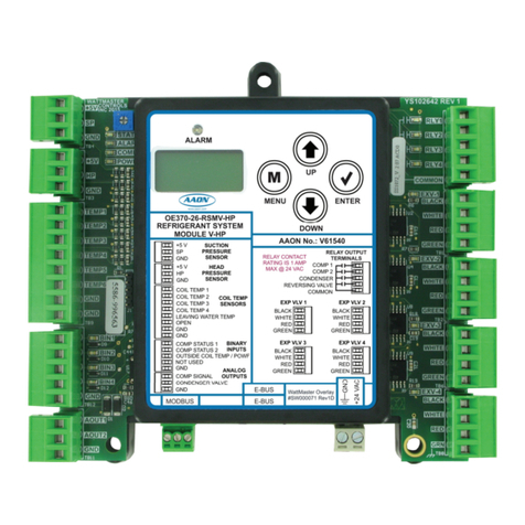
Figure 12: Refrigerant Module LED Locations.......................................................................................................................41
Figure 13: Chiller Pumping Module LED Locations ..............................................................................................................43
Figure 14: Evaporative Condenser Module LEDs .................................................................................................................44
Figure 15: Vestibule Module LEDs...........................................................................................................................................45
Figure 16: LCD Display Screen and Navigation Keys ..........................................................................................................49
Figure 17: BACnet Connection to MS/TP Network ...............................................................................................................80
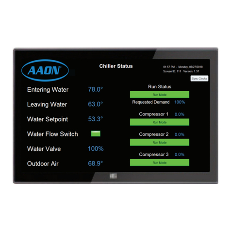
Figure 18: Panel PC with Touchscreen Interface ..................................................................................................................94
Figure 19: Start Screen..............................................................................................................................................................95
Figure 20: Help Screen..............................................................................................................................................................95
Figure 21: System Overview Screen (View Only) .................................................................................................................95
Figure 22: Login Screen ............................................................................................................................................................95
Figure 23: System Overview Screen (Full Access) ...............................................................................................................96
Figure 24: New Passcode Screen ...........................................................................................................................................96
Figure 25: Manage Users Screen ............................................................................................................................................96
Figure 26: System Settings Screen .........................................................................................................................................98
Figure 27: Chiller Pump Status and Waterside Economizer Status Details screen.........................................................99
Figure 28: Evaporator Condenser Status and Vestibule Status Details Screen .............................................................99
Figure 29: RSM Status Details Screen ...................................................................................................................................99
Figure 30: RSM Status and Compressor Staging Status Details Screen..........................................................................99
Figure 31: Scheduling Screen ................................................................................................................................................100
Figure 32: Time Selection Screen..........................................................................................................................................100
Figure 33: Set Time Screen - Individual Day........................................................................................................................100
Figure 34: Holidays Screen.....................................................................................................................................................101
Figure 35: Holiday Set Time Screen......................................................................................................................................101
Figure 36: Temperatures Setpoints Screen ..........................................................................................................................102
Figure 37: Staging Delays and Timing Intervals Setpoints Screen...................................................................................102
Figure 38: Vestibules Setpoints Screen ................................................................................................................................102
Figure 39: Sensor Calibration Setpoints Screen .................................................................................................................102
Figure 40: System Conguration Main Page .......................................................................................................................103
Figure 41: Refrigeration Modules Screens ...........................................................................................................................103
Figure 42: Waterside Economizer Settings Screen.............................................................................................................103
Figure 43: Boiler Pump Settings Screen...............................................................................................................................103
Figure 44: Evaporative Condenser Module..........................................................................................................................103
FIGURES
