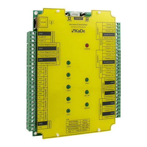
AAT KaDe KDH-KS2024-IP User manual

Installaon Manual
STANDARD CONTROLLER
KDH-KS2024-IP
VERSION 1.0

Standard controller – Installaon manual
2All rights reserved. © AAT HOLDING S.A.
1. Introduction………………………………………………………………………………………….. 3
2. KDH-KS2024-IP controller technical data ………………………………………….. 4
3. General guidelines for controller installation ……………………………………… 5
4. KDH-KS2024-IP controller module …………………………………………………….. 6
5. Reader, exit button and sensor connection ………………………………………… 7
6. Power supply, lock, Ethernet, door sensor and I/O module connection 8
7. APSAAT4 power supply for KDH-KS20XX series controllers ………….….. 9
8. Controller module installation and connections in housing ………………… 10
9. Adding cards to controller memory without software ………………………… 11
CONTENTS

Standard controller – Installaon manual
All rights reserved. © AAT HOLDING S.A. 3
1. Introduction
KDH-KS2024-IP series standard controller is designed to be used in access
control system, managed by KaDe Premium Plus II software. Standard con-
trollers (unlike integrated controllers) are made in the form of modules, placed in
metal enclosure with power supply. They are located in the protected area. Other
system components (readers, electric locks, buttons) are installed next to the
controlled door and connected to the controller. Such solution guarantees higher
system security level, compared to integrated controllers. Readers can use any
identification technology, provided they adopt Wiegand 26-40 bit interface.
KDH-KS2024-IP model can handle:
2 door - two way
4 doors - one way
Models KDH-KS2012/24-IP have built-in IP ports for communication with KaDe
Premium Plus II software, model KDH-KS2012-RS has built-in RS485 port. Both
models are also provided with additional RS485 port, in order to connect exten-
sion module MOD2000INOUT.
List of the most important controller features and parameters is presented
in attached table.
Controller bus, using RS-485 protocol, can be connected to management
software on PC via USB converter or via TCP converter. Software can handle up
to 20 buses, 32 controllers each. Controller models with IP port can communi-
cate directly, via Ethernet network. System can consist of up to 1024 controllers,
what gives 4096 one way doors, when using 4 doors controllers.
It is possible to store up to 20000 cards in controller memory.
For each controller it is possible to connect KDH-MOD2000INOUT module,
equipped with 4 relay outputs, 4 inputs and 4 transistor outputs, controlling
buzzers in readers.
2000 series standard controllers, compatible with KaDe Premium Plus II software.
Symbol Controller description
KDH-KS2012-IP
Standard controller, 1 door - two way, 2 doors - one way, 2 readers ports, TCP port for
communication and RS485 port for extension module, buffer for 20 000 cards, 50 000
events, 20 000 alarms
KDH-KS2024-IP
Standard controller, 2 door - two way, 4 doors - one way, 4 readers ports, TCP port for
communication and RS485 port for extension module, buffer for 20 000 cards, 50 000
events, 20 000 alarms
KDH-KS2012-RS
Standard controller, 1 door - two way, 2 doors - one way, 2 readers ports, RS485 port
for communication and RS485 port for extension module, buffer for 20 000 cards,
50 000 events, 20 000 alarms

Standard controller – Installaon manual
4All rights reserved. © AAT HOLDING S.A.
Parameter or function name Parameter value -
function description
Buffer capacity
- Card buffer 20 000
- Event buffer
- Alarm buffer
50 000 (auto delete of the oldest)
20 000 (auto delete of the oldest)
Electrical parameters
- Supply voltage / Current load 12 VDC / 100 mA
Environmental parameters
- Environment For indoor installation only
- Operating temperature -10°C do +55°C
- Relative humidity 10% - 90%
- Controller module size 140 x 175 mm (W x L)
- Cabinet with power supply size 350 x 304 x 91 (L x W x H)
Communication ports
Direct PC connection - TCP
Extension modules connection - RS485 (dedicated port)
Readers & cards
- readers ports 4 ports - Wiegand interface
- card formats 26 /34 bit Wiegand, self-defined
- card types Compatible with reader technology
- keypad formats on readers 4-bits, without buffering
Inputs
- door contact input NO / NC - 4 inputs
- exit button input NO / NC - 4 inputs
- general inputs NO / NC - 4 inputs
- general inputs—on extension module NO / NC - 4 inputs (option)
Outputs
- electric lock control Relay DC 12V 3A - 4 outputs
- general output Relay DC 12V 3A - 1 output
- general output—on extension module Relay DC 12V 3A - 4 outputs (option)
Access parameters
- access levels 200
- schedules 200
- holidays (single or multiple-day periods) 80 x 64 days
Identification mode Card, PIN, Card or PIN, Card + PIN
Alarm dismiss Synchronize with input state or delay
2. KDH-KS2024-IP controller technical data

Standard controller – Installaon manual
All rights reserved. © AAT HOLDING S.A. 5
3. General guidelines for controller installation
Before controller installation please read this manual.
Controller installation can be performed only by qualified personnel with the
appropriate certificate, authorizing to install and service such equipment
Controller should be installed inside protected area with temperature
above +2°C and normal humidity.
Controllers should be located so that the minimum distance from the cables
and high voltage devices and other devices, that generate electrical noise,
was 2 m. The minimum distance from the telephone line should be 1 m, and
from transmitting devices 8 m.
Controller should be powered from dedicated power supply, type APSAAT4,
described in further part of manual
Wire connections and works with internal controller parts with power on is
strictly prohibited, as it may damage the device
Before connecting controller to power supply, all necessary connections
should be made, in accordance with this manual.
Connection Wire type Distance
Ethernet switch (or router)
> IP controller
UTP-5 twisted-pair wire
with RJ45 connectors
Up to 50 m
(recommended)
(max. 100m)
KDH-MOD2000 module > Controller
(located out of enclosure)
2 pairs of
UTP-5 twisted-pair wire
Up to 800m
(recommended)
(max. 1200m)
Reader > Controller 6-core LIYCY 6x0,75 or
UTP-5 twisted-pair wire
Up to 60m max.
Emergency exit button > Lock >
Controller
2 or 4-core cable
(4×1.0)
150m
Door contact > Controller 2-core cable
(2×0.5)
150m
Exit button > Controller 2-core cable
(2×0.5)
150m
Detector > Controller input 2-core cable
(2×0.5)
150m
Mains power supply 230VAC 3-core cable
(3×1.5)
-
Connection wires table

Standard controller – Installaon manual
6All rights reserved. © AAT HOLDING S.A.
4. KDH-KS2024-IP controller module
1LED
3LED
Communication
port for
software
RS485 port for
extension
module
Door contact
door 4
Door contact
door 3
Door contact
door 2
Door contact
door 1
Relay output
RL5
Relay output
RL4
Relay output
RL3
Relay output
RL2
Relay output
RL1
Power supply
12 VDC
Reader port
RDR 1
Reader port
RDR 2
Reader port
RDR 3
Reader port
RDR 4
Exit button
door 1
Exit button
door 2
Exit button
door 3
Exit button
door 4
Alarm input 1
Alarm input 2
Alarm input 3
Alarm input 4
Enable mode for card adding
without software
Communication password
reset
Control output for additional indicators
LED: POWER & RUN on enclosure cover (option)
Controller operating indicator
Card reading indicator
Two door control mode indicator
Relay X switch indicator
+12 VDC power supply indicator
4 DOOR
2LED
4LED

Standard controller – Installaon manual
All rights reserved. © AAT HOLDING S.A. 7
5. Reader, exit button and sensor connection
Function Czytnik 1 Czytnik 2Color Czytnik 3 Czytnik 4
Power supply - 1RD- 1RD-Black 2RD- 2RD-
Power supply + 1RD+ 1RD+Red 2RD+ 2RD+
Wiegand D0 1RD0 2RD0Green 3RD0 4RD0
Wiegand D1 1RD1 2RD1White 3RD1 4RD1
LED 1LED 2LEDBrown 3LED 4LED
BUZ Yellow OUT BUZ1 MOD OUT BUZ2 MOD OUT BUZ3 MOD OUT BUZ4 MOD
GREEN
WHITE
BROWN
BLACK
RED
GREEN
WHITE
BROWN
READER D1
READER D2
BUTTON D1
BUTTON D2
ALARM LINE 1
ALARM LINE 2
YELLOW OUT BUZ1 MOD
1LED
3LED
2LED
YELLOW OUT BUZ2 MOD
4LED
GREEN
WHITE
BROWN
BLACK
RED
GREEN
WHITE
BROWN
READER D3
READER D4
YELLOW OUT BUZ3 MOD
YELLOW OUT BUZ4 MOD
BUTTON D3
BUTTON D4
ALARM LINE 3
ALARM LINE 4
Notes: Connection between reader and controller: LIYCY type 6-core wire 6x0,75 (shielded) or
twisted-pair UTP-5 (8-core)
Distance : between reader and controller ≤ 60m
Format: Wiegand format for reader, set in the software, needs to match reader’s output format.
Indicator of communication with reader: when user presents card to the reader, LED (RD_OK) on
the controller module lights up—only, when connection with reader is correct and controller port
works correctly. Otherwise, LED will not light up.

Standard controller – Installaon manual
8All rights reserved. © AAT HOLDING S.A.
6. Power supply, lock, Ethernet, door sensor and I/O module connection
Extension module - KDH-MOD2000INOUT
Notes: Address dipswitches should be left at default settings (all ON). Present
firmware of 2000 series controllers supports only one module. In future it will be
possible to connect more modules, with different addresses, to one controller.
PSU 12VDC
Integrated in
APSAAT4
Lock
NC type lock
Lock
NO type lock
Alarm
siren
I/O module
Switch TCP
RS485 A
RS485 B
RS485 GND
1 C
1 NC
1 N0
1 ALM
GND
2 C
2 NC
2 N0
2 ALM
GND
3 C
3 NC
3 N0
3 ALM
GND
4 C
4 NC
4 N0
4 ALM
GND
1 BUZ
2 BUZ
3 BUZ
4 BUZ
+12VDC
GND
RL1 RL2 RL3 RL4
Relays and
LED diodes LED indicator
power
To RS485
port
Control of BUZ
in readers
Relay outputs (C/NC/NO) x 4
Alarm inputs ALM/GND x 4
VDC
VDC
VDC
OUTPUT 1-4
CONTROL
OUTPUTS
FOR DOOR
LOCKS 1-4
1LED
2LED
4LED
3LED
D_S1-4 DOOR SENSORS
Address
dipswitches
LED indicator
RUN

Standard controller – Installaon manual
All rights reserved. © AAT HOLDING S.A. 9
7. APSAAT4 power supply for KDH-KS20XX series controllers
To Ethernet
Power supply 12VDC 5A
Control outputs
EPS
PSU
LoB
Battery 7Ah
Mains supply 230VAC
Power
distributor
Locks power supply
KDH-MOD2000INOUT module
Controller module
Fuse T3,15A/250V
AUX1+
LoB
PSU
EPS
Power distributor
Provides two independent outputs, protected by polymer fuses:
to controller and I/O module AUX1/COM - 0,9A, 13,8 VDC
to locks, sirens AUX2/COM - 4A, 13,8 VDC
Control outputs - relay and transistor with LED indication:
EPS - technical output for absence of AC supply
PSU - output signalling absence of DC voltage/power supply failure
LoB - output signalling low battery voltage
Above mentioned outputs should be connected with free alarm line on controller or on extension
module and monitoring schedule should be enabled.
Diagram above shows only connections, which should be made inside the enclosure, between
power supply module, controller module, I/O module, tamper switch and battery.
Detailed information about all parameters and terminals in APSAAT4 power supply are specified
in the operating manual of the power supply on the website:
http://www.aat.pl/pl/products/2930/APSAAT4
Base hole
Enclosure door tamper switch
1LED
2LED
3LED
4LED

Standard controller – Installaon manual
10 All rights reserved. © AAT HOLDING S.A.
8. Controller module installation and connections in housing
Controller and extension module (option) should be installed in a dedicated buffer power
supply housing. Dedicated housing APSAAT4, designed for models KDH-KS2012-IP, KDH
-KS2012-RS and KDH-KS2024-IP, is recommended.
Before installing controller module, 4 metal spacer bars (included) should be installed in
bottom holes. Since controller modules have different sizes, number of holes are made
at the bottom of housing. The base point for all models, which can be installed in this
enclosure, is the hole located in upper left corner of controller module installation space
(location is shown on previous page). The buffer power supply, mounted in this housing,
has capacity of 5A. Power supply output is split and individually protected - for modules
(0,9 A) and locks (4 A). This capacity allows connecting controller module, 2 or 4 read-
ers and 2 or 4 electric locks (even electromagnetic locks with current consumption 500
mA). Housing is adapted to internal installation of 7Ah battery.
NOTE: If it’s necessary to provide longer operation time for controller, separate supply
power with 18Ah rechargeable battery should be connected to the battery cables de-
rived from APSAAT4. To avoid the reverse charge current please install diode in series
circuit. The manufacturer strongly discourages direct connection to the power supply in
APSAAT4 battery with a larger capacity than 7Ah because it requires a larger charging
current.
After installing module in the enclosure with screw kit, following connections should be
made (shown on previous page):
connect supply voltage output (AUX 1 12VDC) with controller terminals
additional terminals on controller module supply socket can be connected to I/O
module, according to figure on previous page.
connect controller RS485 port, using 3-core signal wire, with corresponding port on
I/O module, according to figure and terminals description on page 8
install battery at the bottom of housing and connect dedicated wires (red (+) and
black (-), coming from the left side of power supply module).
connect housing tamper switch to free alarm line input (enable monitoring sched-
ule in software - Always enabled)
connect readers, locks, buttons and door status wires to terminals on controller
edges
connect cable with RJ45 connector to Ethernet socket, located in the upper left cor-
ner of the controller module. Other end of the cable should be connected to Ether-
net network.
connect mains power supply 230 VAC to electrical terminal block in the bottom part
of housing (through existing fuse), in accordance with colors of wires, coming from
the terminal block to the power supply
After finishing all connections, once again check, if they are all correct and only after
this turn on the mains voltage 230 V and check if controller is working properly.
After turning on mains voltage, observe LED indicators on power supply module, con-
troller and I/O module. 12V voltage presence indicators should first light up on power
supply module, and then on controller (POWER LED) and I/O module.
Next, RUN diode on controller module and I/O module should start blinking. Thereafter,
LEDs on readers should light up.
Housing is equipped with dismantled door, which can be disassembled for connecting
wires, after disconnecting grounding wire. Housing can be closed with two screws, fas-
tened on the right . Opening of the enclosure is monitored by tamper switch, which gen-
erates alarm, if it’s not temporarily disabled by administrator, for service purposes.

Standard controller – Installaon manual
All rights reserved. © AAT HOLDING S.A. 11
9. Adding cards to controller memory without software
2000 series controllers have ability to add cards to the controller database, using
connected standard reader, without connecting with management software.
It’s very useful function on system commissioning and testing stage, because it
allows fast and simple adding of cards with privileges. Using this method, up to
3000 cards can be added, all with administrator rights and working in 7/24h
mode. After communicating controller with the software, at a further stage of in-
stallation, it is possible to remotely delete these cards, but they are not overwrit-
ten by cards added with the software. If we want to have uniform card database
in entire system, obviously cards added with this method should be deleted and
card database should be sent from the management software on PC. Function of
adding cards with this method is enabled as default, but it can be disabled after
connecting controller with the software. Adding cards using reader affects only
database of controller, to which reader used for reading cards is connected. If
system consists of more controllers, this procedure should be repeated individu-
ally for each controller.
Procedure for creating programming card:
1. Push the button Mode, located on the upper edge of controller and hold it
for 3 seconds. Read any card in the reader - it will be programming card. To
exit programming mode, push the button twice and wait for 30 seconds.
Procedure for adding cards to the controller memory:
1. Read programming card in the reader once. Entering to programming mode
is indicated by blinking LED on the reader alternately, in red and green.
2. Read card, which should be added. LED on the reader will flash in red for
1,2 seconds. It indicates adding card. Read further cards, which should
be added.
1. In order to finish procedure of adding cards read the programming card
again or wait for 12 seconds.
Procedure for deleting cards from controller memory:
1. Read the programming card in the reader twice. Entering to programming
mode is indicated by LED on the reader flashing green.
2. Read the card, which should be deleted. LED on the reader will flash in red
for 1, 2 seconds. It indicates deleting card. Read further cards, which should
be deleted.
3. In order to finish procedure of adding cards read the programming card
again or wait for 12 seconds.
Procedure for deleting all cards from controller memory:
1. Read the programming card in the reader three times. Entering to program-
ming mode is indicated by LED on the reader flashing green.
2. After 4 seconds read programming card again. All cards are deleted and
reader will leave the programming mode.

Table of contents
Other AAT Controllers manuals