Integrated Access Controller – Installation manual
10 AAT SYSTEMY BEZPIECZEŃSTWA Sp. z o.o.
All rights reserved.
Programming Step Keystroke Combination
1. Enter Program Mode ﹡(Master Code) #
2. To disable door open detection
OR
2. To enable door open detection
5 0 # (factory default)
5 1 #
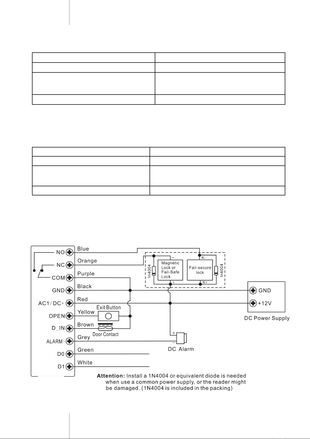
Door Detecting
Door Open Too Long (DOTL) warning. When used with an optional magnetic con-
tact or built-in magnetic contact of the lock, if the door is opened normally, but
not closed after 1 minute, the inside buzzer will beep automatically to remind
people to close the door and continue for 1 minute before switching off automati-
cally.
Door Forced Open warning. When used with an optional magnetic contact or built
-in magnetic contact of the lock, if the door is opened by force, or if the door is
opened after 60 seconds of the electro-mechanical lock not closed properly, the
inside buzzer and alarm output will both operate. Enter Master code # or valid
user card /PIN to silence
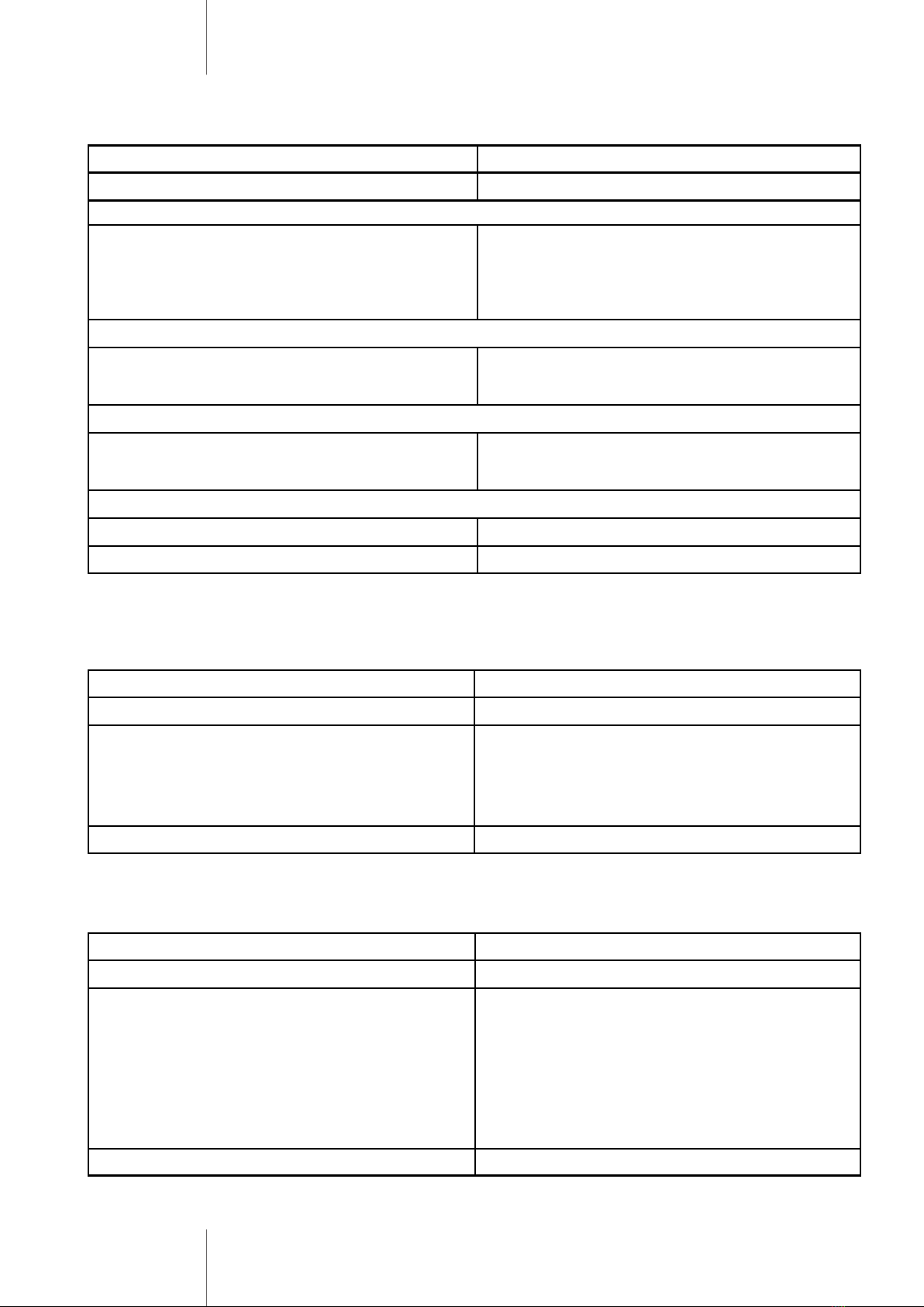
Set Strike-out Alarm
The strike-out alarm will engage after 10 failed card attempts (Factory is OFF).
It can be set to deny access for 10 minutes (61#) or engaging or disengage only
after entering a valid card/PIN or Master code (62#).
Set Audible and Visual Response
Programming Step Keystroke Combination
1. Enter Program Mode * (Master Code) #
2. Strike-Out OFF
OR
2. Strike-Out ON
OR
2. Strike-Out ON (Alarm)
6 0 # (factory default)
6 1 # Access will be denied for 10 minutes
6 2 # Silence alarm
3. Exit *
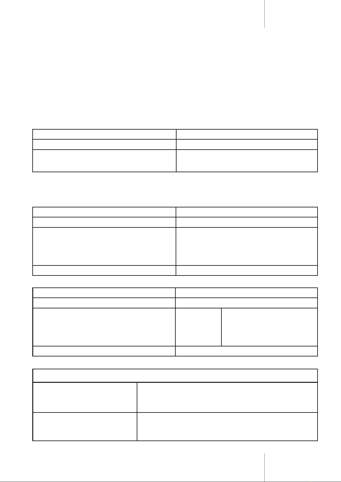
Programming Step Keystroke Combination
1. Enter Program Mode * (Master Code) #
2. Control Sounds
OR
2. Control LED
OR
2. Control Keypad Backlit
OFF = 7 0 #
OFF = 7 2#
OFF = 7 4 #
ON = 7 1 #
ON = 7 3 #
ON = 7 5 #
(factory defaults are ON)
3. Exit *
Master Cards Usage
Using Master Card to add and delete card users
Add a Card User 1. (Read Master Add Card)
2. (Read User Card)
Repeat Step 2 for additional user cards
3. (Read Master Add Card)
Delete a Card User 1. (Read Master Delete Card)
2. (Read User Card)
Repeat Step 2 for additional user cards
3. (Read Master Delete Card)