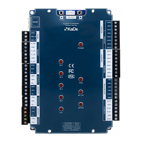
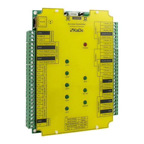
AAT KaDe KDH-KZ2000-IP-U User manual

Integrated Access Controller – Installation manual
AAT SYSTEMY BEZPIECZEŃSTWA Sp. z o.o.
All rights reserved. 1
Installaon Manual
INTEGRATED ACCESS CONTROLLER
KDH-KZ2000-IP-U
KDH-KZ2000-IP-M
VERSION 1.0
Installaon Manual
INTEGRATED ACCESS CONTROLLER
KDH-KZ2000-IP-U
KDH-KZ2000-IP-M
VERSION 3.0 25-06-2020

Integrated Access Controller – Installation manual
2 AAT SYSTEMY BEZPIECZEŃSTWA Sp. z o.o.
All rights reserved.
1. Introduction …………..…………..…………..…………..…………..……………….. 3
2. Controller technical data …………..…………..…………..…………..…….…. 4
3. Controller wiring diagram …………..…………….………………..……………. 6
4. Controller installation …………..…………..…………..…………..…………….. 9
5. Management in standalone mode ………….…………..…………..……... 10
6. Programming codes table …………..…………………...…..…………..…... 14
7. Management in network mode …………….……...…….……...….….….. 15
8. Rules for Installation ……………...…….……………...…….……………...… 15
CONTENTS

Integrated Access Controller – Installation manual
AAT SYSTEMY BEZPIECZEŃSTWA Sp. z o.o.
All rights reserved. 3
1. Introduction
Controller KDH-KZ2000-IP-U
Controller KDH-KZ2000-IP-M
The KDH-KZ2000-IP-U_M controller has been designed for access control
system and to be mounted on a wall without any additional enclosure. 32 bit
processor ensures fast and reliable data processing. This is one door controller.
With additional reader (also with keypad) it can use for two way control. Recom-
mended supply power type AWZ-200 plus 7Ah battery.
It’s possibility to set one from four identification mode:
- Card only (default mode)
- PIN only
- Card or PIN
- Card + PIN
KZ-1000-IP can work in standalone (programming from keypad) or in net-
work mode. In network mode it can work on-line or off-line with supervisor KaDe
Premium Plus software II on PC.
KDH-KZ2000-IP-U_M include following components in one cabinet:
• controller module for 1 door
• card reader - 125 kHz ISO UNIQUE - model KDH-KZ2000-IP-U
or
• card reader - 13,56 MHz MIFARE – model KDH-KZ2000-IP-M
• keypad for PIN with bell button
• LED and Buzzer
• anti-disassemble sensor

Integrated Access Controller – Installation manual
4 AAT SYSTEMY BEZPIECZEŃSTWA Sp. z o.o.
All rights reserved.
Parameter or function name Parameter value
or function description
Buffer capacity
- Card buffer 20 000 (2 000 in standalone mode)
- Event buffer
- Alarm buffer 50 000
20 000
Electrical parameter
- Supply power 12 VDC
- Current load < 110 mA
- anti-static capability: YES
Environment parameter
- Environment For indoor installation only
- Working Temperature From+2°C to 55°C
- Relative Humidity 0% - 95%
- Size (L x W X H) 122 x 77 x 39 mm
Communication ports
For connection with KaDe Premium Plus - TCP
For additional module connection - RS485 (for future used)
Readers and Cards
- Integrated reader For UNIQUE card, read range 5 - 10 cm (U)
For MIFARE card, red range 2– 5 cm (M)
- External (for two way control) 26 (U)/34(M) bit Wiegand output format
- Card format ISO UNIQUE (125 kHz)
MIFARE (14443A) (13,56 MHz)
- External reader keypad PIN format 4-bits, without buffering
Inputs
- Door contact input NO / NC (NO - default)
- Exit button input NO / NC (NO - default)
- PIR input NO / NC (NO - default)
Relay output
- Strike (lock) control Relay DC 12V 1A (NO / C / NC)
- Alarm control Relay DC 12V 1A (NO / C / NC)
- Bell control NO/NC
Access level parameter
- Access level 200
- Schedule 184
- Holiday 32
Identification mode Card, Card + PIN, PIN , Card or PIN
Alarm relive Automatic, manually by operator or by card
2. KDH-KZ2000-IP-U_M controller technical data

Integrated Access Controller – Installation manual
AAT SYSTEMY BEZPIECZEŃSTWA Sp. z o.o.
All rights reserved. 5
Controller module include:
• Communication port TCP for direct connection with KaDe Premium Plus II
• Second reader port for two way control (Wiegand output format)
• Door status sensor input
• Exit button input
• Movement detector input
• Communication port RS485 for connection with additional modules
(for future used)
• Supply Power connectors (+12V, 110 mA)
• Lock control relay output
• Alarm relay output
• Bell control output from keypad key
LED located on front panel - upper left light in:
RED - as supply power indicator
Blue - access granted (light when door unlocked)
Green - programming mode
All components are mounted in esthetics case. KDH-KZ2000-IP-U_M controller is
designed for indoor use only. When entry from outdoor is needed, additional out
door reader should be connected ( np. C-61-W26/34, C-71-W26/34 for version U
or C-100/110M for version M)
Controller back side - connectors view
(pin connectors description on the next page)
J6
J7
J5
J4
J3
8 pin
2 pin
6 pin
4 pin
4 pin

Integrated Access Controller – Installation manual
6 AAT SYSTEMY BEZPIECZEŃSTWA Sp. z o.o.
All rights reserved.
TX+ White-
orange TCP network Transmission +
TX- Orange TCP network Transmission -
RX+ White-
green TCP network Receiver +
RX- Green TCP network Receiver -
J3 connector - 4 pin
D0 Green Wiegand D0 - external reader port
D1 White Wiegand D1 - external reader port
BUZ Blue LED /Buzzer of external reader
SW Purple Door contact
AN Gray Exit button
ALM Yellow PIR sensor input
485+ Black RS485 port - signal +
485- Red RS485 port - signal -
-12V Black Controller supply power -12 VDC
-12V Black Supply power for extern. reader -12 VDC
+12V Red Controller supply power +12 VDC
+12V Red Supply power for extern. reader +12 VDC
J4 connector - 4 pin
J5 connector - 6 pin
2NC Black Lock relay - out NC
2C Red Lock relay - out C
2NO White Lock relay - out NO
1NC Yellow Alarm relay - out NC
1C Orange Alarm relay - out C
1NO Green Alarm relay - out NO
J6 connector - 8 pin
BE Black Bell button
BE Red Bell button
J7 connector - 2 pin

Integrated Access Controller – Installation manual
AAT SYSTEMY BEZPIECZEŃSTWA Sp. z o.o.
All rights reserved. 7
J5 connector - 6 pin
2NC Black
2C Red
2NO White
1NC Yellow
1C Orange
1NO Green
Electric lock connection — NC type
Electric
lock
VDC
J5 connector - 6 pin
2NC Black
2C Red
2NO White
1NC Yellow
1C Orange
1NO Green
Electric lock connection — NO type
Electric
lock
VDC
D0 Green
D1 White
BUZ Blue
SW Purple
AN Gray
ALM Yellow
485+ Black
485- Red
J6 connector - 8 pin
Reader, door status sensor, exit button and PIR motion detector connection
12
VDC
Reader
Door status sensor
PIR
detektor Exit
button
J5 connector - 6 pin
2NC Black
2C Red
2NO White
1NC Yellow
1C Orange
1NO Green
Alarm sounder connection
Alarm
sounder
VDC

Integrated Access Controller – Installation manual
8 AAT SYSTEMY BEZPIECZEŃSTWA Sp. z o.o.
All rights reserved.
Switch TCP
Supply power
12 VDC AWZ-200
Battery
7 Ah Door
bell
Electric
lock
Sound
alarm
KDH-KZ2000-IP-U_M
controller
RS485
For future use
Alarm
sensor
Exit
button
Door
Status sensor
Reader
KaDe Premium Plus II
supervisor software
Buzzer
Battery
+
Tamper
Administrator and
communication
password reset
(read notes p.15)
J3
J6 J4
J7
J5
Block diagram of KDH-KZ2000-IP-U_M controller accessories connection
(details description on the previous page)

Integrated Access Controller – Installation manual
AAT SYSTEMY BEZPIECZEŃSTWA Sp. z o.o.
All rights reserved. 9
Installation instruction
1. Unscrew the bottom screw and separate
the rear panel of the controller. Use it as a tem-
plate for the mounting holes. Drill 4 holes for
the mounting screws and one in the middle for
the cables.
2. Attach the back cover of the controller to
the wall. Place the plugs from the wires in the
appropriate sockets and drag them to the other
side of the wall.
3. Mount the controller module on the back
cover. Pay attention to the slot on the top edge
of the controller case and use it as a catch.
4. Push the controller module with the hous-
ing to the back cover and secure it with a screw
from the bottom.
Wall
Back cover
Controller module
Metal cabinet
Gap

Integrated Access Controller – Installation manual
10 AAT SYSTEMY BEZPIECZEŃSTWA Sp. z o.o.
All rights reserved.
5. Programming controller in standalone mode
Controller KDH-KZ2000-IP-U_M can be operated in stand-alone mode or
network under the supervisory software KaDe Premium Plus II installed on your
computer.
Working in stand-alone mode (without communication with the supervisor soft-
ware on the PC) must be programmed using the controller's built-in keypad.
There is no in this mode the possibility to monitor the system "on-line" and gen-
erate reports. Cards added in this mode works without any time limit. This mode
is recommended for the control a few doors with a small number of users.
It is also possible operation of the controller in the "off-line" after being pro-
grammed by supervisory software with controller connecting using TCP port.
Programming procedure using the keyboard controller
Signalling functions:
• audible alarm (buzzer)
• Single long sound - the operation succeeded or enter the menu
• Triple sound - the operation was not successful
• Quad sound - at the selected position is already stored card
• Triple sound - card with this number is already added
• Optical indicator (LED)
• Red LED - Power on
• Blue LED - confirmation of the validity of the operation
• Green LED / steady light - programming mode
5. 1 The procedure for entry into the programming mode:
• Press *
• Enter the master code (default "000000")
• Green LED should light up permanently
If no password is entered correctly within 20 seconds after pressing * it auto-
matically returns to normal. Even after entering the programming mode, no key-
pad operation for 20 seconds to exit the programming mode. After entering the
programming mode, you can make only one type of operation. To perform the
next operation re-enter the programming mode.
Notes: Default admin code 000000 must be change after first enter into pro-
gramming mode for own using 41 command code. Leave default code allows un-
authorized persons enter into programming mode and add own card. Reset ad-
min password is available from KaDe Premium Plus II software - > Controller
setup -> Context menu/Initialize. New password should be download to the con-
troller.
Procedure exited from programming mode:
(After programming)
• Press # - a single sound, red LED light.

Integrated Access Controller – Installation manual
AAT SYSTEMY BEZPIECZEŃSTWA Sp. z o.o.
All rights reserved. 11
5.2 Configuring basic parameters include:
• controller initialization
• enable / disable the alarm
• tamper sensor alarm
• parameters of exit button
• door status sensor parameters
• alarm parameters
5.2.1 Controller initialization
• After entering the programming mode enter the code 11
• The process takes about 30 seconds, during which the controller gener-
ates beep every 0.5 seconds
• After this time, the controller generates a long beep and exits the pro-
gramming mode
Initialization operation erases the controller configuration settings (including a
database of cards) and restore the factory settings. Administrator password has
been set to default (000000).
5.2.2 Enable / disable alarm
After entering the programming mode enter the code:
• 121 alarm on
• 122 alarm off
5.2.3 Tamper Alarm
After entering the programming mode enter the code 13, then:
• Code 00 when you want to disable the monitoring of the sensor
• code 01 to activate monitoring
When a tamper alarm is activated an attempt to remove the unit from the wall
will turn on internal buzzer in the controller and an alarm sound. This option
should be activate only after installing the controller on the wall.
5.2.4 Setting the parameters of the exit button
After entering the programming mode enter the code 141, then:
• 01 code for the NO type button (normally open - Default setting)
• 00 code for the NC type button (normally closed)
After entering the programming mode enter the code 142, then:
• 01 code button enable (default)
• 00 code button disabled
5.2.5 Setting the parameters of the door sensor detection line
After entering the programming mode enter the code 151, then:
• 01 code for the NO type sensor (normally open - Default setting)
• 00 code for the NC type sensor (normally closed)
After entering the programming mode enter the code 152, then:
• value from 00 to 99 seconds (default-3 sec.)
This is the time to close the door after time to unlock leaf.
5.2.6 Setting the parameters of the alarm line
After entering the programming mode enter the code 161, then:
• Code 01 for NO type detector (normally open - default setting.)
• Code 00 for NC type detector (normally closed)
After entering the programming mode enter the code 162, then:
• value from 00 to 99 seconds (default - 0 sec. default settings)
This is the time of relay alarm action.
Value 0 second time means “Alarm action Synchronous with input state”.
Value from range 1 to 99 means “Alarm action delay time”.
After entering the programming mode enter the code 163, then:
• value 1 if the alarm siren will be activated relay 1
• value 2 when the alarm siren will be activated relay 2
• value 3 when the alarm siren will be activated relay 1 and 2
• value 4 when none of these relays will not switch

Integrated Access Controller – Installation manual
12 AAT SYSTEMY BEZPIECZEŃSTWA Sp. z o.o.
All rights reserved.
5.3 Setting the control parameters and identification mode of doors
After entering the programming mode enter the code 21, then:
• value from 00 to 99 seconds (default - 3 sec.)
This is the time by which, when a valid card or code is used the door will be
unlocked.
After entering the programming mode enter the code identification mode:
• 221 - Card only
• 222 - Card + PIN
• 223 - PIN only
• 224 - Card or PIN
6. User Management
In standalone mode can be added up to 2000 users. Each user must be assigned
with ID from 0000 to 1999 in the programming process and then assigned ac-
cess card number read by the reader. This allows the system administrator can
remove the user from the database without the need a card (which can be erg.
lost), knowing only the user's ID code. Cards added in standalone mode have full
access to the passage (24 hours a day, 7 days a week). In contrast to the added
cards from the program, which can be assigned to a limited level of access. To
avoid the need for dual record cards and disadvantages related to the two data-
bases cards in practice, it is recommended to use only one controller mode -
standalone or network. Before adding users, it is recommended that the admin-
istrator has created a list of users with assigned four-digit ID code. This makes it
easier to add new users later, and in particular the removal of lost cards.
6.1 Adding a package of cards
After entering the programming mode enter the code 31, then:
• Enter the ID of the first user of the package
• Close the cards one of the other to the reader
After read each card reader will generate a single beep.
• Repeat the operation for the next card
• After loading press #
Read the card will be credited automatically generated ID numbers. The process
is best preceded by the preparation of a list of IDs, user names and card num-
bers.
6.2 Adding a single card
After entering the programming mode enter the code 32, then:
• Enter the user ID from the list
• Close the cards one of the other to the reader
After you read the card reader will generate a single beep and automatically ex-
its the programming mode.
6.3 Adding a package of cards with PIN codes (6 digits)
After entering the programming mode enter the code 33, then:
• Enter the ID of the first user of the package
• Close the cards one of the other to the reader
• Enter the PIN -> enter the PIN again
• Repeat the operation for subsequent reading cards with PIN codes
After each added card reader generate a single beep. Read the card will be cred-
ited automatically generated ID numbers.
• After loading press #

Integrated Access Controller – Installation manual
AAT SYSTEMY BEZPIECZEŃSTWA Sp. z o.o.
All rights reserved. 13
6.4 Adding a single card with a PIN code
After entering the programming mode enter the code 34, then:
• Enter the user ID from the list
• Close the cards one of the other to the reader
• Enter the PIN -> enter the PIN again
After you read the card and enter your PIN, the controller will generate a single
beep and automatically exits the programming mode.
6.5 Adding a group of users with PIN codes
After entering the programming mode enter the code 35, then:
• Enter the ID of the first user of the package
• Enter the PIN -> enter the PIN again
• Repeat the operation to enter PIN codes for next users
After each added user controller will generate a single beep. PIN codes entered
will be added to the next automatically generated ID numbers.
• after loading press #
6.6 Adding a single user with a PIN code
After entering the programming mode enter the code 36, then:
• Enter the user ID from the list
• Enter the PIN -> enter the PIN again
After a user added the controller generates a single beep and automatically exits
the programming mode.
7.1 Deleting a single user with a card or PIN
After entering the programming mode enter the code 37, then:
• Enter the user ID from the list
or
• Close deleting card to the reader
After you read the card controller will generate a single beep and automatically
exits the programming mode.
7.1 Removal of all users
After entering the programming mode enter code 38.
This process can take more than 10 seconds. Then the controller will generate a
single beep and automatically exits the programming mode.
8.1 Administrator PIN code - used to enter the programming mode
After entering the programming mode enter the code 41, then:
• Enter the PIN -> enter the PIN again
After adding a new administrator PIN code controller will generate a single beep
and automatically exits the programming mode.
NOTE: The default master code 000000 is mandatory to change after the
first entry into this mode on your own code using the command 41.
Leaving the default code allows third parties to enter into this mode and
operations, e.g. adding his own card. If you do not know the master
code reset can be performed from within the program KaDe - Controller
setup/Context menu/ Initialize Controller. The new password should be
download to all controllers.
8.2 PIN code security
After entering the programming mode enter the code 42, then:
• Enter the PIN -> enter the PIN again
After adding a PIN controller generates a single beep and automatically exits the
programming mode. This code can be used in the event of a forced entry - the
doors are unlocked mode and alarm signal is sent to the on-line monitoring at
the operator station.

Integrated Access Controller – Installation manual
14 AAT SYSTEMY BEZPIECZEŃSTWA Sp. z o.o.
All rights reserved.
Parameter name
or function
Function code
(after enter into programming mode)
Programming mode
Enter programming mode * plus admin code PIN
Exit the programming mode #
Basic parameters
Controller initialization 11
Enabling alarm
Disabling alarm 121
122
Tamper alarm 13 (00 disable 01 enable)
Exit button input line parameters 141 (01 - type NO, 00 - type NC)
142 (00 disable 01 enable)
Door magnet input line parameters
Door open delay (unlock time)
Door open time-out (after unlock time-out)
151 (01 - type NO, 00 - type NC)
21 (00 - 99) sec., 3 sec. default
152 (00 - 99) sec., 3 sec. default
Alarm input line parameters
Alarm action delay
Alarm relay output
161 (01 - type NO, 00 - type NC)
162 (00 - 99) sec., 0 sec. default
163 (1-RL1, 2-RL2, 3-RL1&2, 4–no out)
Access mode setup
Card only 221
Card + PIN 222
PIN only 223
Card or PIN 224
User management
Add card continuously 31
Add single card 32
Add card + PIN continuously 33
Add single card + PIN 34
Add user with PIN continuously 35
Add single user with PIN 36
Delete single card 37
Delete all cards 38
Admin password setup (programming mode) 41
Threaten code setup 42
Programming codes table - standalone mode
Notes: Default admin code 000000 must be change after first enter into programming
mode for own using 41 command code. Leave default code allows unauthorized persons
enter into programming mode and add own card. Reset admin password is available
from KaDe Premium Plus software - > Controller setup -> Context menu/ Initialize. New
password should be download to the controller.

Integrated Access Controller – Installation manual
AAT SYSTEMY BEZPIECZEŃSTWA Sp. z o.o.
All rights reserved. 15
Programming the controller in network mode
Controller KDH-KZ2000-IP-U_M can operate in stand-alone mode or net-
work mode under the supervisory software installed on computer.
It is also possible operation of the controller in the "off-line" after programming
with the supervisory software when the controller is connected through an IP
port.
Supervisory program on PC gives a much more powerful programming and mon-
itoring system based on controllers KDH-KZ2000-IP-U_M. A detailed description
of controller programming in network mode refer to the instructions for the
KaDe Premium Plus II software and the help files dynamically displayed on
the operator panel.
General guidelines for the installation of the controller
• Before installing the controller should be familiar with this manual.
• Installation of the controller can be performed only by qualified personnel
with the appropriate certified to install and service this type of equipment.
• The controller must be installed within a protected space at a temperature
of above + 2 ° C and normal humidity.
• Controllers in the system should be located so that the minimum distance
from cables and high-voltage devices and other devices that generate elec-
trical noise was 2 m. The minimum distance from telephone lines should be
1 m, and from 8 m transmitting devices.
• As the housing of the controller is equipped with a tamper sensor so care
must be taken to the surface for mounting the controller housing it was
hard and smooth.
• The controller should be powered from a linear power supply with backup
battery with parameters. 12 VDC, 1A. This takes into account the possible
supply of an electric lock with the same power supply. In this case the at
the lock terminals should be installed diode 1N4004 in the reverse direction.
• Wiring and performing any work on the internal components of the control-
ler while power is categorically prohibited. This can lead to damage.
• Before connecting the controller to the power supply must perform all the
necessary connections in accordance with the instructions.
• The connection to the computer is to be implemented using the IP port.
• Each controller must be set to a different IP address.
NOTES: Tamper and recover administrator and communication password
(for location look at diagram on page 8):
Keeping pressing the button (with small spring), device will under tamper status.
To clear administrator password by pressing the button for three times, and
administrator password return to default 000000 and clear communication
password.

Integrated Access Controller – Installation manual
16 AAT SYSTEMY BEZPIECZEŃSTWA Sp. z o.o.
All rights reserved.

Integrated Access Controller – Installation manual
AAT SYSTEMY BEZPIECZEŃSTWA Sp. z o.o.
All rights reserved. 1
Kontroler zintegrowany – Instrukcja instalacji
AAT Holding S.A. Wszelkie prawa zastrzeżone.
Instrukcja instalacji
KONTROLER ZINTEGROWANY
KDH-KZ2000-IP-U
KDH-KZ2000-IP-M
WERSJA 3.0 25-06-2020

Kontroler zintegrowany – Instrukcja instalacji
2 AAT SYSTEMY BEZPIECZEŃSTWA Sp. z o.o.
Wszelkie prawa zastrzeżone
1. Informacje wstępne…………..…………..…………..…………..…………..…… 3
2. Dane techniczne kontrolera…………..…………..…………..…………..……. 4
3. Schemat blokowy podłączenia akcesoriów do kontrolera….….…… 6
4. Montaż kontrolera…………..…………..…………..…………..……………..…… 9
5. Programowanie kontrolera w trybie autonomicznym…………..….. 10
6. Tabela kodów programowania…………..…………..…………..……………. 14
7. Praca kontrolera w trybie sieciowym…………………………...…….……. 15
8. Ogólne wytyczne dotyczące instalacji kontrolera……………...……. 15
SPIS TREŚCI

Kontroler zintegrowany – Instrukcja instalacji
AAT SYSTEMY BEZPIECZEŃSTWA Sp. z o.o.
Wszelkie prawa zastrzeżone. 3
1. INFORMACJE WSTĘPNE
Kontroler KDH-KZ2000-IP-U
Kontroler KDH-KZ2000-IP-M
Kontrolery zintegrowane typu KDH-KZ2000-IP-U_M przeznaczone są do pra-
cy w systemach kontroli dostępu. 32-bitowy procesor gwarantuje szybką i nieza-
wodną pracę kontrolera, zwłaszcza w trybie monitorowania na żywo. Jest to kon-
troler jednego przejścia. Przejście to może być kontrolowane jedno- lub dwu-
stronnie. Aby zrealizować kontrolę dwustronną należy dołączyć do portu kontro-
lera drugi czytnik. Może to być również czytnik z klawiaturą. Kontroler wraz z
czytnikiem z klawiaturą oferuje 4 tryby identyfikacji użytkownika: karta, PIN,
karta lub PIN, karta+ PIN. Każdy użytkownik może mieć swój indywidulany kod
PIN, również w trybie autonomicznym.
Kontroler może pracować w trybie autonomicznym (programowanie z klawiatury)
lub sieciowym pod programem nadzorczym KaDe Premium Plus II. Zalecany za-
silacz - AWZ 200 z akumulatorem 7Ah.
Urządzenie integruje w sobie następujące elementy:
• moduł kontrolera 1 przejścia
• czytnik kart zbliżeniowych:
- w standardzie 125 kHz ISO UNIQUE - model KDH-KZ2000-IP-U
lub
- w standardzie 13,56 MHz MIFARE – model KDH-KZ2000-IP-M
• klawiaturę do wprowadzania kodu PIN i programowania oraz przycisk
dzwonkowy
• sygnalizator optyczny (diody LED) i akustyczny (brzęczyk)
• czujnik antysabotażowy

Kontroler zintegrowany – Instrukcja instalacji
4 AAT SYSTEMY BEZPIECZEŃSTWA Sp. z o.o.
Wszelkie prawa zastrzeżone
Nazwa parametru
lub funkcji Wartość parametru
lub opis funkcji
Pojemność pamięci
- pamięć kart 20 000 (2 000 w trybie autonomicznym)
- pamięć zdarzeń
- pamięć alarmów 50 000
20 000
Parametry elektryczne
- napięcie zasilania 12 VDC
- pobór prądu < 110 mA
- odporność na przepięcia statyczne TAK
Parametry środowiskowe
- otoczenie Tylko do instalacji wewnątrz pomieszczeń
- temperatura pracy Od +2°C do 55°C
- wilgotność względna 0% - 95%
- wymiary 122 x 77 x 39 mm
Porty komunikacyjne
Do połączenia z KaDe Premium Plus II - TCP
Do podłączenia do modułów rozszerzeń - RS485 (do wykorzystania w przyszłości)
Czytniki i karty
- zintegrowany w urządzeniu Na karty UNIQUE, zasięg 5 - 15 cm (U)
Na karty MIFARE, zasięg 2 - 5 cm (M)
- dodatkowy Zgodny z 26(U)/34(M) bit Wiegand
- format kart ISO UNIQUE (125 kHz)
MIFARE CLASSIC (14443A) (13,56 MHz)
- format kodów klawiatury czytnika dodatkow. 26(U), 34(M), 4-bitowy, bez buforowania
Linie dozorowe
- wejście czujnika stanu drzwi NO / NC (ustaw. domyślne NO)
- wejście do przycisku wyjścia NO / NC (ustaw. domyślne NO)
- wejście do czujki PIR NO / NC (ustaw. domyślne NO)
Wyjścia sterujące
- zamkiem elektrycznym Przekaźnikowe DC 12V 1A
- sygnalizatorem alarmu Przekaźnikowe DC 12V 1A
- Dzwonek NO / NC
Parametry dotyczące dostępu
- liczba poziomów dostępu 200
- liczba terminarzy 184
- liczba dni świątecznych 64
Tryb identyfikacji Karta, Karta + PIN, PIN, Karta lub PIN
Kasowanie alarmu Automatyczne, przez operatora lub kartą
2. Dane techniczne kontrolera KDH-KZ2000-IP-U_M
This manual suits for next models
1
Table of contents
Languages:
Other AAT Controllers manuals
Popular Controllers manuals by other brands

inVENTer
inVENTer Connect. installation instructions

Distech Controls
Distech Controls ECB-PTU Series installation guide

GEZE
GEZE IQ box KNX UP quick start guide

Adaptec
Adaptec 3405 Installation and user guide

Johnson Controls
Johnson Controls VA-7700 Series manual

Desert Aire
Desert Aire CM35xx quick start guide