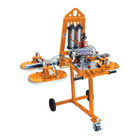
ABACO MACHINES AVL480 User manual

ABACO MACHINES (USA)
14508 S. Garfield Ave., Paramount, CA 90723, USA
Tel : 310-532-0366 Fax : 310-532-0499
Email : sales@abacomachines.com
Website : www.abacomachines.com
ABACO MACHINES
OPERATION MANUAL
ABACO GLASS VACUUM LIFTER
(AVL480)


I.GENERAL:
- Abaco Glass Vacuum Lifter is the equipment that is designed to
use for lifting and moving large size glass.
- This item has ability to rotate up to 90 degree vertically and
horizontally.
- There are two ways of suction cups positioning which fit well with
various size of glass.
II. STRUCTURE:
- Abaco The Glass Vacuum Lifter consists of a main frame which
connected to the suction cups via a joined bar.
- The main frame is attached to the hanging bar via swivel joint.
- Besides, the main frame is equipped with an electric box and motor.
2
Length (A)
inches (mm) Width (B)
inches (mm) Height (C)
inches (mm)
59 (1500)¹⁄₁₆ 68 (1735)⁵⁄₁₆ 12 (305)¹⁄₁₆
Net weight
lbs (kg)
156.2 (71)

Model
Work Load Limit (W.L.L)
Diameter of suction cup
Number of suction cups
AVL480
1056 lbs (480 kg)
6
Power source for charging 220V
Minimum applicable size of glass sheet
Battery charge time
Pump operational period by Battery
(non-stop)
6 hrs 30 min
2 hrs 15 min
Maximum lead time to achieve the required
vacuum pressure
10 seconds
USA International
9 ¹³⁄₁₆ ” (250mm)
70 ⅞ x 39 ⅜ ” ”
(1800x1000mm)
Specifications:
110V
Rotate angle Left 90 , Right 90
o o
Tilt angle 90o

III. STRUCTURE SPECIFICATIONS:
1. Overall:
3

1 AVL480-01 Main frame 1
2 AVL480-02 Hanger 1
3 AVL480-03 Bushing 1
4 AVL480-04 Washer Ø20 1
5 AVL480-05 Bolt M20x40 1
6 AVL480-06 Shaft 1 1
7 AVL480-07 Pad 1 1
8 AVL480-08 Traverse beam, left 1
9 AVL480-09 Allen bolt M6x12 16
10 AVL480-10 Swivel plate 1
11 AVL480-11 Pad 2 1
12 AVL480-12 Pad 3 1
13 AVL480-13 Air compression clamp 2
14 AVL480-14 Air compression 1
15 AVL480-15 Screw M5x10 14
16 AVL480-16 Pad 4 1
17 AVL480-17 Solenoid box 1
18 AVL480-18 Nut M4 2
19 AVL480-19 Cover 1 1
20 AVL480-20 Screw M6x15 2
21 AVL480-21 Base, control panel 1
22 AVL480-22 Allen bolt M6x10 4
23 AVL480-23 Washer Ø6 28
24 AVL480-24 Box, electric 1
25 AVL480-25 Handle block 1
26 AVL480-26 Cover, pump 1
27 AVL480-27 Screw M4x15 5
28 AVL480-28 Label 1
POS. CODE DESCRIPTION QTY.
4

29 AVL480-29 Plastic plate 2
30 AVL480-30 Motor 1
31 AVL480-31 Bolt M6x25 4
32 AVL480-32 Plastic bushing 4
33 AVL480-33 Rubber cap 1 6
34 AVL480-34 Bolt 36
35 AVL480-35 Rubber cap 2 2
36 AVL480-36 Suction cup 6
37 AVL480-37 Spring 6
38 AVL480-38 Pad 5 1
39 AVL480-39 Turn-knob M10 2
40 AVL480-40 Traverse beam, right 1
41 AVL480-41 Circlip Ø14 5
42 AVL480-42 Washer Ø14 5
43 AVL480-43 Lever sub assembly 1
44 AVL480-44 Pin 1
45 AVL480-45 Spring tension 1
46 AVL480-46 Blind flange 1
47 AVL480-47 Lock nut M8 1
48 AVL480-48 Crank handle 1
49 AVL480-49 Handle grip 1
50 AVL480-50 Allen bolt M8x60 1
51 AVL480-51 Washer Ø8 1
52 AVL480-52 Allen bolt M8x20 1
53 AVL480-53 Rubber cap 3 1
54 AVL480-54 Lock joint 1
55 AVL480-55 Shaft 2 1
56 AVL480-56 Allen bolt countersunk M5x15 4
57 AVL480-57 Nut M6 4

IV. INSTRUCTION FOR USE:
1. Before operating:
- Ensure the equipment is connected to suitable voltage power (See
sectionII)
-Ensurethepoweriscontinuoussuppliedduringthewholeoperate
process.
- Inspect the air tube system, ensure there is not sign of leaking or
breaking.
- Ensure the slab surface is clean, no sign of any liquid such as water
andoil.
-Ensureallthesuctioncupsarecarefullycleanedup.
-Inspectallthebuttons,levers,alarm.
2. Operating Instruction:
A. When the glass is positioned in vertical dimension:
Step 1: Moving the glass vacuum lifter close to the glass.
Note:
11
- Adjusting the suction cups position to adapt to the glass size (See
appendix3.B)
-Ensurethelifteris setatthecentreoftheglassrelatively.

Step 2: Place the glass vacuum lifter closely to the glass surface.
Step 3: Press “ ” (green button) to activate attractVACUUM
Note: Ensure that the glass surface is well attracted by all the suction
cups simultaneously.
12

Step 5: Place the glass in desired position.
Note:
-Gentlyoperatewhenliftingtheglassupanddown.
- Do notswitch lever to adjust the angle to90 degree and set the glass
inverticaldimensionwhileattracting.
Step 6: Press button and remove the glass vacuum“RELEASE”
lifter from the glass.
Note: Ensure that the pressure gauge lowering down to “0” before
removethelifter.
13

Note:
Once press button, the pressure“VACUUM’’
gaugehandwillmovetotheright.
Please make sure that the hand is in the
section from to-0.8 bar -1 bar.
Step 4: Starting lifting and moving the glass.
While the system is in attract mode, we can rotate the glass to 90
degree.( )Seeappendix3.C
Note:
-Beawarethatthepressure gaugemustalwaysshowingtheindicator
from to duringattractingprocess.-0.8bar -1bar
-Donotpress (redbutton)whileattractingtheglass.“RELEASE”
14

B. When the glass is positioned in horizontal dimension.
Step 1: Moving the lifter to get closed to the glass.
Note:
-Adjusting the suction cups position to adapt to the glass size (See
appendix3.B)
-Ensuretheglassvacuumlifterissetatthecentreoftheglass
15
-Before ,adjustingthelifter'sinclinationactivateattractingfunction
sothatallthesuctioncupsareinhorizontalposition.
( )SeeAppendix3.A

Step 2: Place the lifter closely to the glass surface.
Note: Make sure that all the suction cups need to be attracting to
the glass surface.
Step 3: Press (green button) to activate attracting.“VACUUM”
16

Note:
Once press button, the“VACUUM”
pressure gauge hand will move to the right.
Please make sure that the hand is in the
section from to-0.8 bar -1 bar.
Step 4: Starting lifting and moving the glass.
While the system operate, we can rotate the glass to 90 degree
direction. (See appendix 3.C)
Note:
-Beawarethat thepressuregaugealways showingtheindicatorfrom
0.8bar -1barto duringattractingprocess.
-Donotpress (redbutton)whilesuckthe glass.“RELEASE”
17

Step 5: Place the glass in desired position.
Note:
Operate carefully when the glass up and down.
18

Step 6: Press button and remove the lifter from the“RELEASE”
glass.
Note: Ensure that the pressure gauge lower down to “0” before
remove the lifter.
19

3. Appendix:
A/ Adjusting the suction cups to horizontal dimension.
Pull the handgrip lock (as shown in the picture) and rotate the
frame to horizontal dimension.
20

- Loosen turn-knob (anticlockwise direction).
- Move suction cup follow to requirement place, tighten turn-knob
(clockwise direction)
21

C/ Rotating main frame manipulation.
- Pull the handgrip lock (as shown in the picture)
- Next, rotate the glass vacuum lifter follow to your requirement.
Note: Pin-clock automatically install into hole position for angle
adjustment.
22

23
VI. WARRANTY:
At the time of delivery, it is necessary to inspect the Abaco Glass
Vacuum Lifter to make sure that it has not been damaged during
shipment. Any claims must be submitted within 8 days from the date
of delivery. We provide a warranty on the Abaco Glassone (1) year
Vacuum Lifter from the date of purchase.
During warranty period, we will provide the replacement parts at
no charge (shipping and handling fees may apply).
Warranty coverage is void if:
- The operator failed to comply with the instructions in the manual.
- The specifications are not followed.
- Damage is due to inadequate maintenance and inspections.
- Damage is due to improper storage and/or usage.
- Repairs were performed by the user without our permission.
- Non-original spare parts were used.
V. :INSPECTION & MAINTENANCE
-Schedule periodic maintenance of the lifter, especially the suction
cups.
-Reserve expendable and/or necessary spare parts for maintenance
or repair.
- Check the electrical system, turn off the power after use.
-Regularly check the tightening conditions of all the bolts and
nuts.
- Always keep the lifter clean and away from grease or other
substances as they may reduce the effectiveness of the suction cups
and cause them lose their grip.
- Store the lifter in a well-ventilated place, avoid places with high
heat or humidity.
Table of contents
Other ABACO MACHINES Lifting System manuals
Popular Lifting System manuals by other brands

Adam Hall
Adam Hall STAGELIFT100 user manual

Tractel
Tractel T 1000 Original Operation and Installation Manual

Hercules Haulers
Hercules Haulers TSMM260006 instructions

Upright
Upright AB38 Operation and parts manual

Manitou
Manitou 80 VJR Operator's manual

Hubbell
Hubbell EH-09 Installation and operation instructions

Sinoboom
Sinoboom GTJZ1932ME Maintenance manual

QUALITY LIFTS
QUALITY LIFTS Q4P07 Installation, operation & maintenance manual

Harmar Mobility
Harmar Mobility SL600 HD Installation & service manual

AMGO Hydraulics
AMGO Hydraulics SML-7 Installation and service manual

Sinoboom
Sinoboom TB20J Plus Operation manual

Lukas
Lukas LX LIFT operating instructions