ABB A200-L User manual

Operation Manual / A200-L
Table of contents
© Copyright 2021 ABB. All rights reserved. HZTL4036_EN Rev.T December 2021
Operation Manual / A200-L
1 Introduction............................................................................................................ 4
1.1 Essential information.................................................................................................... 5
1.2 Registered trademarks................................................................................................. 5
1.3 Layout and function of the turbocharger ................................................................ 6
1.4 Locations of the rating plates.................................................................................... 8
2 Safety ...................................................................................................................... 9
2.1 Introduction ................................................................................................................... 9
2.2 CE conformity................................................................................................................ 9
2.3 Definition of mandatory signs .................................................................................. 10
2.4 Definition of safety instructions .............................................................................. 10
2.5 Intended use ................................................................................................................. 11
2.6 Deflagration on gas engines ..................................................................................... 12
2.7 Warning plates on the turbocharger........................................................................ 13
2.8 Turbocharger rating plate.......................................................................................... 13
2.9 Periodic check of the pressure vessels.................................................................... 15
2.10 Lifting of loads ............................................................................................................. 16
2.11 Prerequisites for operation and maintenance....................................................... 17
2.12 Hazards during operation and maintenance ......................................................... 18
2.13 Safe operation............................................................................................................. 20
2.14 Safe maintenance ....................................................................................................... 20
3 Removal and installation .................................................................................... 26
3.1 Turbocharger weight ................................................................................................. 26
3.2 Removing the turbocharger...................................................................................... 26
3.3 Installing the turbocharger ...................................................................................... 28
4 Commissioning .................................................................................................... 31
4.1 Oil supply ....................................................................................................................... 31
4.2 Inspection procedures................................................................................................ 31
4.3 Commissioning after taking out of operation...................................................... 33
5 Monitoring during operation.............................................................................. 34
5.1 Oil pressure, oil temperature.................................................................................... 34
5.2 Admissible air inlet temperature .............................................................................. 37
5.3 Turbocharger speed .................................................................................................... 37
5.4 Low pressure measurement at the filter silencer ................................................ 40
6 Operation and service ......................................................................................... 41
6.1 Noise emission ............................................................................................................. 41
6.2 Service work................................................................................................................. 42
6.3 Expected replacement intervals .............................................................................. 46
6.4 Flexible turbocharger cut-out .................................................................................. 47

Operation Manual / A200-L
Table of contents
© Copyright 2021 ABB. All rights reserved. HZTL4036_EN Rev.T December 2021
6.5 Stopping the engine................................................................................................... 48
7 Periodic maintenance.......................................................................................... 49
7.1 Foreword to maintenance......................................................................................... 49
7.2 Cleaning the filter silencer ........................................................................................ 50
7.3 Changing the filter strip on the filter silencer casing.......................................... 52
7.4 Cleaning the compressor during operation .......................................................... 54
7.5 Cleaning the turbine during operation................................................................... 58
7.6 Draining the gas outlet casing ................................................................................. 62
8 Troubleshooting................................................................................................... 63
8.1 Malfunctions when starting...................................................................................... 63
8.2 Malfunctions during operation ................................................................................ 64
8.3 Surging of the turbocharger..................................................................................... 66
8.4 Malfunctions when stopping.................................................................................... 67
8.5 Speed measurement system.................................................................................... 68
9 Disassembly and assembly................................................................................. 70
9.1 Introduction ................................................................................................................. 70
9.2 Material required.......................................................................................................... 71
9.3 Weights of assemblies................................................................................................ 72
9.4 Disassembly and assembly of the filter silencer casing ...................................... 73
9.5 Dismantling the filter silencer .................................................................................. 78
9.6 Dismantling wall insert and diffuser....................................................................... 80
9.7 Axial clearance A prior to disassembly ................................................................... 86
9.8 Dismantling the insulation (≤ A275-L) .................................................................... 87
9.9 Dismantling the gas inlet casing (≤ A275-L) .......................................................... 88
9.10 Dismantling the nozzle ring (≤ A275-L)................................................................... 89
9.11 Dismantling the gas inlet casing (A280-L)............................................................. 90
9.12 Dismantling the nozzle ring (A280-L) ...................................................................... 91
9.13 Fitting the nozzle ring (≤ A275-L)............................................................................. 93
9.14 Fitting the gas inlet casing (≤ A275-L).................................................................... 94
9.15 Fitting the insulation (≤ A275-L) .............................................................................. 95
9.16 Fitting the nozzle ring (A280-L) ............................................................................... 96
9.17 Fitting the gas inlet casing (A280-L)....................................................................... 98
9.18 Axial clearance A after assembly.............................................................................. 99
9.19 Fitting the diffuser ................................................................................................... 100
9.20 Fitting wall insert ....................................................................................................... 101
9.21 Fitting the filter silencer.......................................................................................... 105
9.22 Table of tightening torques.................................................................................... 108
10 Taking a turbocharger out of operation......................................................... 110
10.1 Possible emergency repairs..................................................................................... 110
10.2 Taking defective turbochargers out of operation .............................................. 111
11 Mothballing the turbocharger.......................................................................... 116
11.1 Taking the engine out of operation for up to 12months .................................. 116
11.2 Taking the engine out of operation for more than 12months ......................... 117

Operation Manual / A200-L
Table of contents
© Copyright 2021 ABB. All rights reserved. HZTL4036_EN Rev.T December 2021
12 Material and Disposal........................................................................................ 118
12.1 REACH and RoHS Compliance Declaration For Products .................................. 118
12.2 Disposing of turbocharger components .............................................................. 119
13 Spare parts ......................................................................................................... 120
13.1 Ordering spare parts................................................................................................ 120
13.2 Spare Part - Illustrations........................................................................................... 122
14 Tools .................................................................................................................... 140
Figures................................................................................................................. 142
Tables .................................................................................................................. 144

Operation Manual / A200-L
1 Introduction /
© Copyright 2021 ABB. All rights reserved. HZTL4036_EN Rev.T December 2021
1 Introduction
Page 4 / 145

Operation Manual / A200-L
1 Introduction / 1.1 Essential information
© Copyright 2021 ABB. All rights reserved. HZTL4036_EN Rev.T December 2021
1.1 Essential information
Design variants
This document is valid for different design variants of turbochargers. There may be sections
and descriptions of components that are not relevant for a specific turbocharger variant.
Please contact an ABB Turbocharging Service Station if you have any questions regarding a
design variant (see Contact information at www.abb.com/turbocharging).
Accuracy of illustrations
The illustrations in this document are general in nature and intended for ease of understand-
ing. Differences in detail are therefore possible.
1.2 Registered trademarks
The trademarks of outside companies are used in this document. These are marked with the
® symbol.
Page 5 / 145

Operation Manual / A200-L
1 Introduction / 1.3 Layout and function of the turbocharger
© Copyright 2021 ABB. All rights reserved. HZTL4036_EN Rev.T December 2021
1.3 Layout and function of the turbocharger
Fig.1: Layout and function of the turbocharger
01 Filter silencer 08 Gas inlet casing
02 Thrust bearing 09 Bearing casing
03 Radial plain bearing 10 Diffuser
04 Radial plain bearing 11 Compressor wheel
05 Gas outlet casing 12 Compressor casing
06 Turbine wheel 13 Air-outlet silencer (option)
07 Nozzle ring
Page 6 / 145

Operation Manual / A200-L
1 Introduction / 1.3 Layout and function of the turbocharger
© Copyright 2021 ABB. All rights reserved. HZTL4036_EN Rev.T December 2021
Mode of operation
The turbocharger is a turbomachine and consists of the following main components:
¡Turbine
¡Compressor
These components are installed on a common shaft and form the rotor.
The exhaust gases of the internal combustion engine flow through the gas inlet casing (08)
and the nozzle ring (07) onto the turbine wheel (06). The turbine wheel uses the energy con-
tained in the exhaust gas to drive the rotor and, hence, the compressor wheel(11).
The exhaust gases then reach the atmosphere through the exhaust gas pipe connected to
the gas outlet casing(05).
The compressor wheel (11) sucks in fresh air and presses the compressed air into the cylin-
ders.
The air passes through the filter silencer(01) to the compressor wheel(11). The air then
flows through the diffuser(10) and exits the turbocharger through the compressor cas-
ing(12). An air outlet silencer(13) is optionally available. If installed, this will reduce the
amount of noise generated by the components at the outlet side after the compressor cas-
ing.
The rotor runs in two radial plain bearings(03/04) which are located in the bearing cas-
ing(09) between the compressor and turbine. The axial thrust bearing(02) is located at the
compressor end.
The plain bearings are connected to a central lubricating oil duct which is normally supplied
by the lubricating oil circuit of the engine. The oil outlet always lies at the deepest point of
the bearing casing(09).
The turbocharger is equipped with an oil tank which is integrated in the bearing casing (9).
This oil tank supplies the bearings of the rotor with oil until standstill in the event that a mal-
function of the lubrication oil system causes an emergency stop of the engine.
Page 7 / 145
Operation Manual / A200-L
1 Introduction / 1.4 Locations of the rating plates
© Copyright 2021 ABB. All rights reserved. HZTL4036_EN Rev.T December 2021
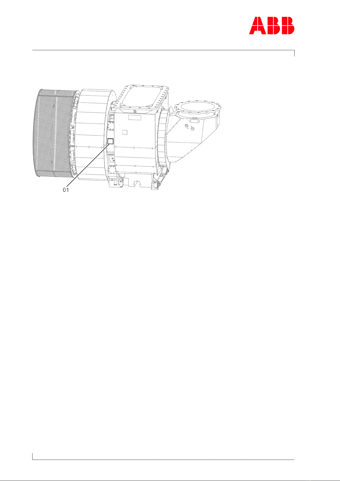
1.4 Locations of the rating plates
Fig.2: Locations of the rating plates
One rating plate (01) each is attached on the left and the right side of the turbocharger bear-
ing casing.
Page 8 / 145

Operation Manual / A200-L
2 Safety / 2.1 Introduction
© Copyright 2021 ABB. All rights reserved. HZTL4036_EN Rev.T December 2021
2 Safety
2.1 Introduction
Turbochargers manufactured by ABB reflect the state of the art. The respective safety and
health protection requirements are met. This ensures safe operation of the turbocharger.
Nevertheless, there may be some residual risks during operation of and work on the tur-
bocharger which:
¡are caused by the turbocharger itself or its accessories.
¡are caused by the operating equipment used or supplies and materials.
¡are a consequence of insufficient compliance with safety instructions.
¡are a consequence of insufficient or inappropriate performance of maintenance and in-
spection work.
The operating company is responsible for defining measures that regulate safe access to
and safe handling of the turbocharger.
All instructions contained in this chapter must be observed for safe and trouble-free opera-
tion of the turbocharger and during all work on the turbocharger.
All further safety instructions contained and specifically identified in every chapter of this
Operation Manual (Definition of safety instructions →10) must also be observed.
2.2 CE conformity
Information
ABB turbochargers comply with the Machinery Directive 2006/42/EC and are partly com-
pleted machinery as defined by Article 2 g in this directive.
Page 9 / 145

Operation Manual / A200-L
2 Safety / 2.3 Definition of mandatory signs
© Copyright 2021 ABB. All rights reserved. HZTL4036_EN Rev.T December 2021
2.3 Definition of mandatory signs
To be worn at all times
Protective clothing Safety footwear to protect
against mechanical hazard and
risk of falling
Table1: Personal protective equipment to be worn at all times
To be worn specific to the respective task
Safety glasses Safety goggles
Safety gloves to protect
against
- Mechanical hazard
- Chemical hazard
- Thermal hazard
- Electrical hazard
Respiratory mask to protect
against
- Dusts
- Gases
Safety helmet Ear protection
Table2: Personal protective equipment to be worn specific to the respective task
2.4 Definition of safety instructions
WARNING
Definition of Warning
Non-compliance or inaccurate compliance with working or operating in-
structions indicated by this symbol and the word WARNING can lead to seri-
ous injuries to personnel and even to fatal accidents.
uWarning signs must always be observed.
CAUTION
Definition of Caution
Non-compliance or inaccurate compliance with working or operating in-
structions indicated by this symbol and the word CAUTION can lead to seri-
ous damage to engine or property with grave consequences.
uCaution signs must always be observed.
Page 10 / 145
This manual suits for next models
7
Table of contents
Other ABB Batteries Charger manuals


