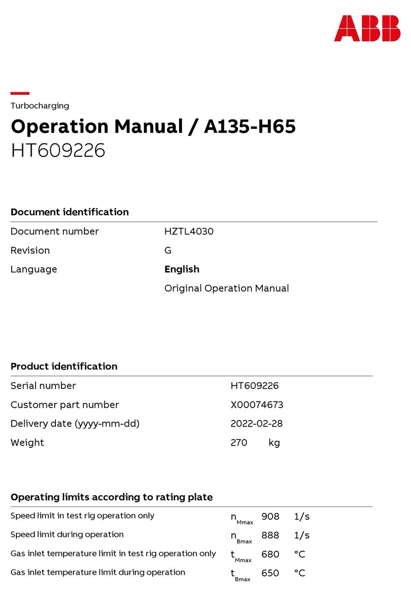
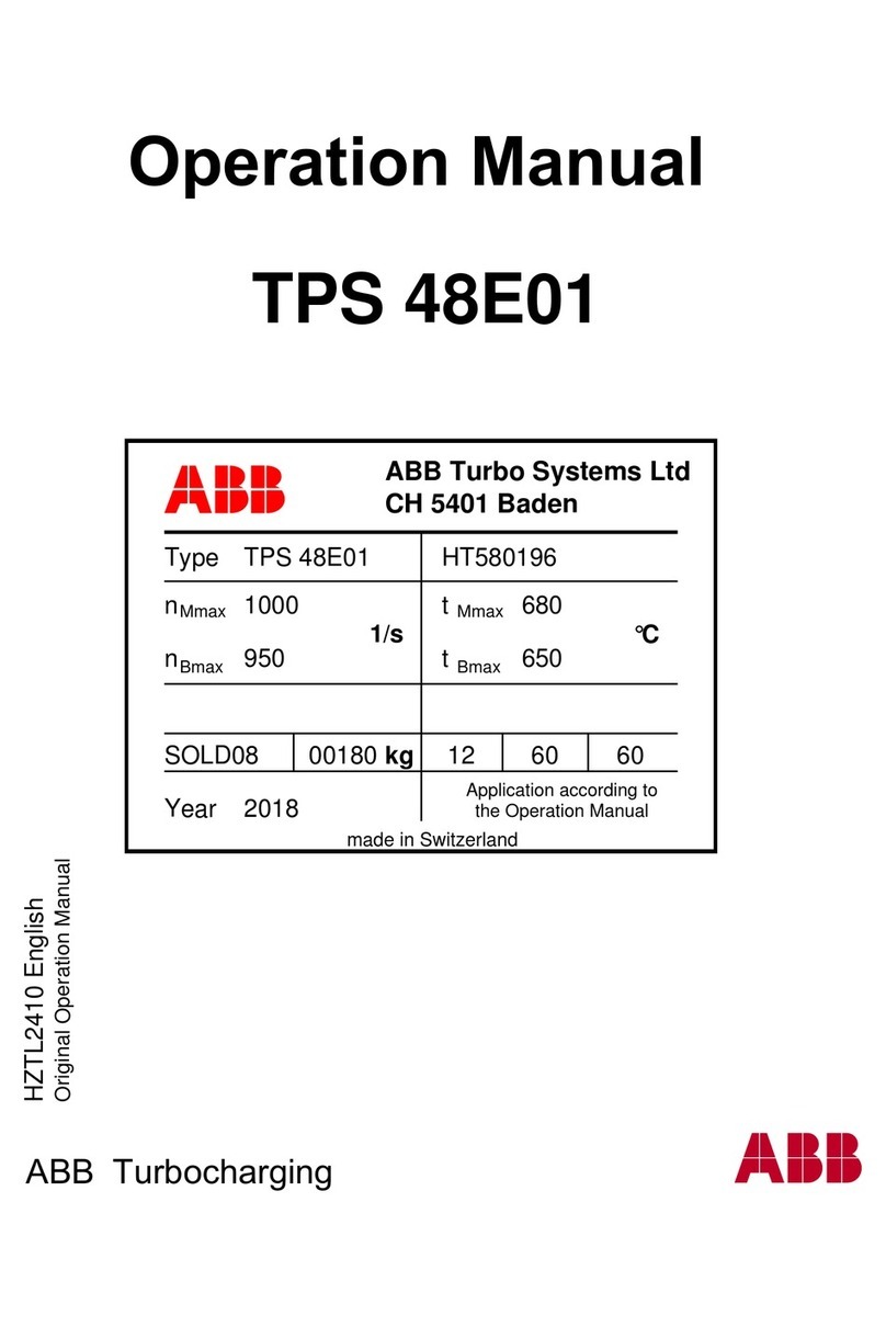
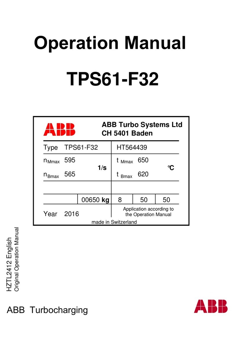
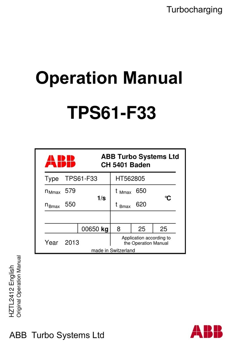
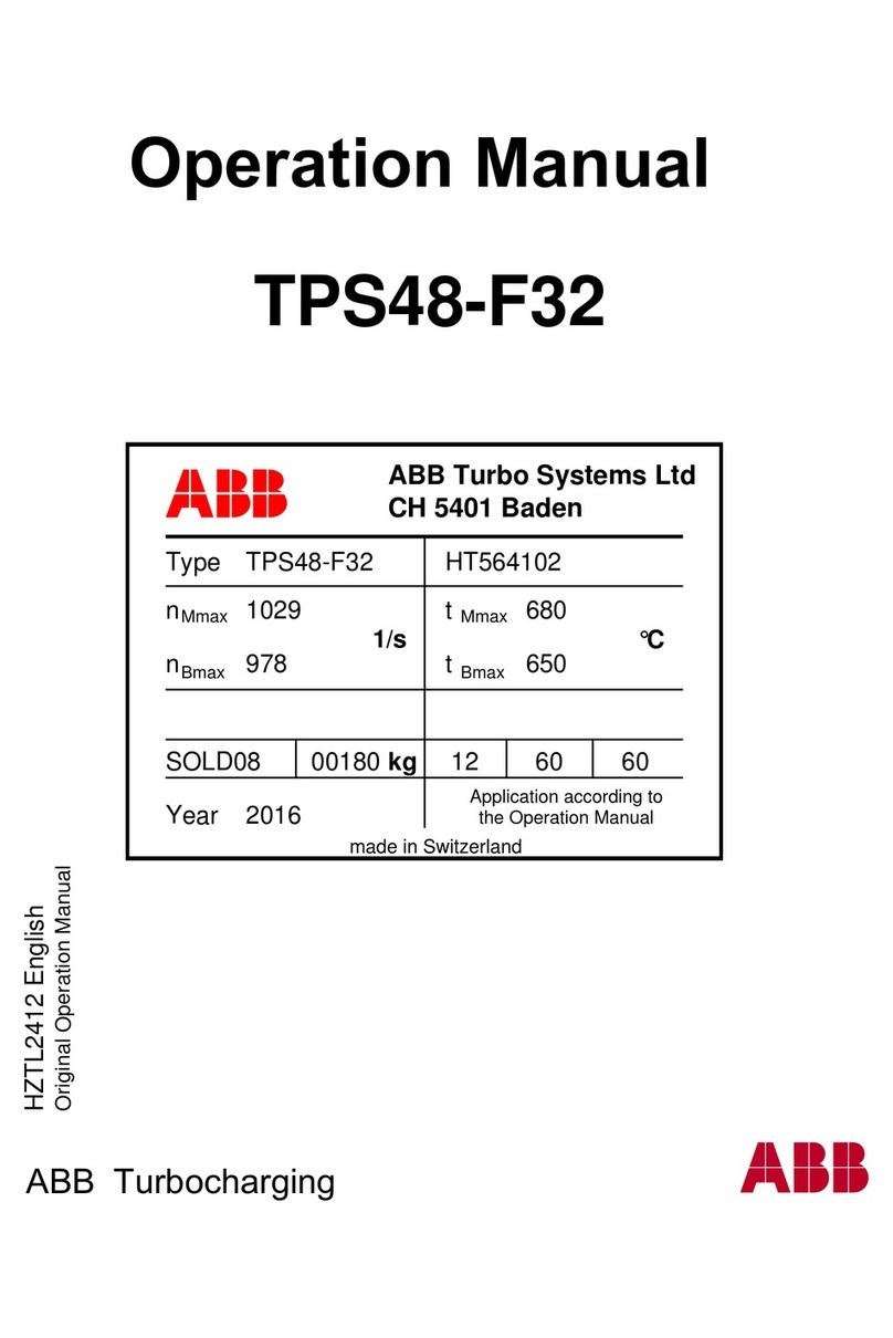
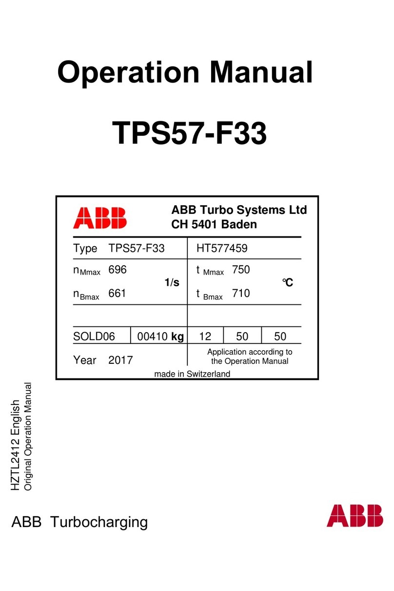
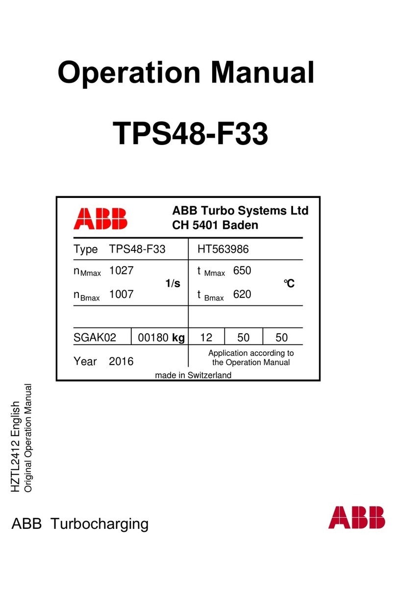
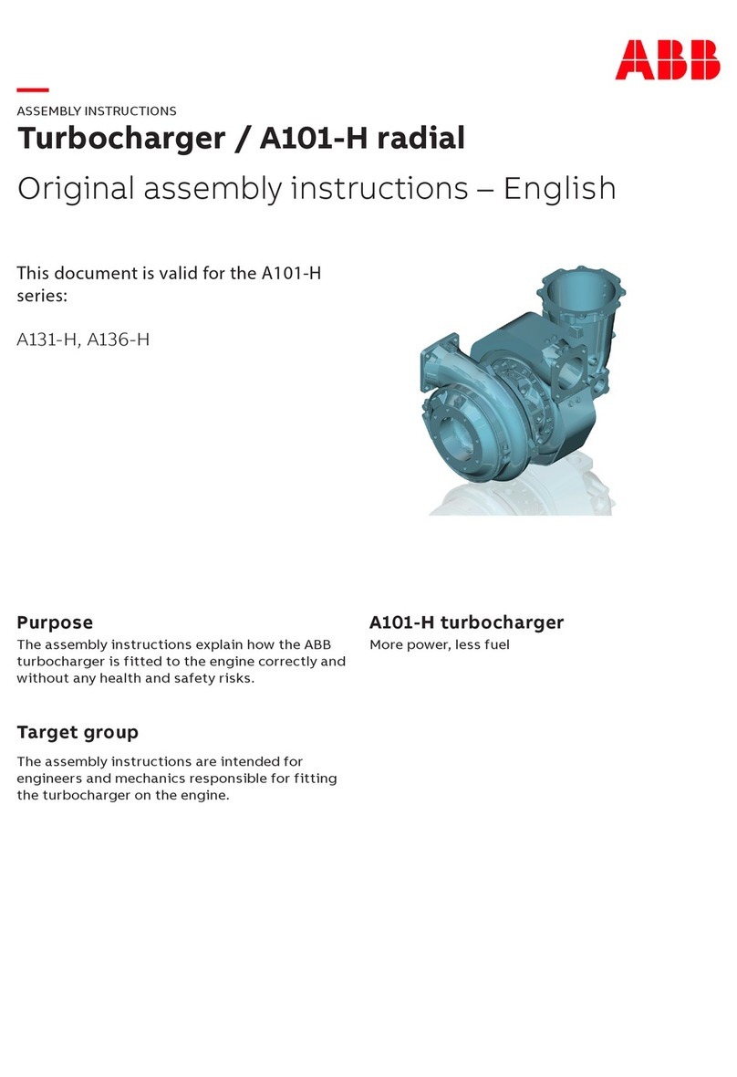
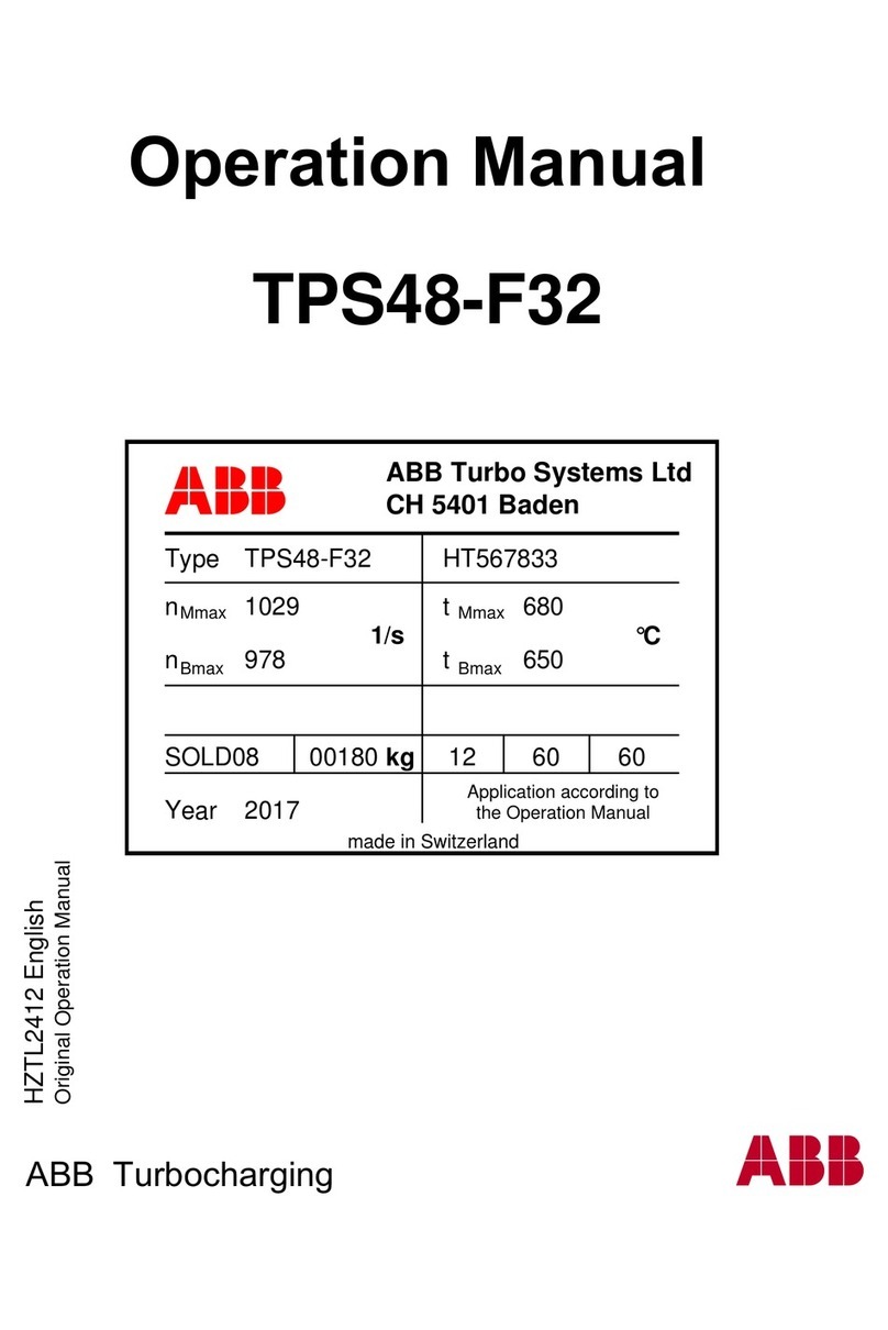
ABB XAC25131 User manual

Turbo Systems Switzerland Ltd
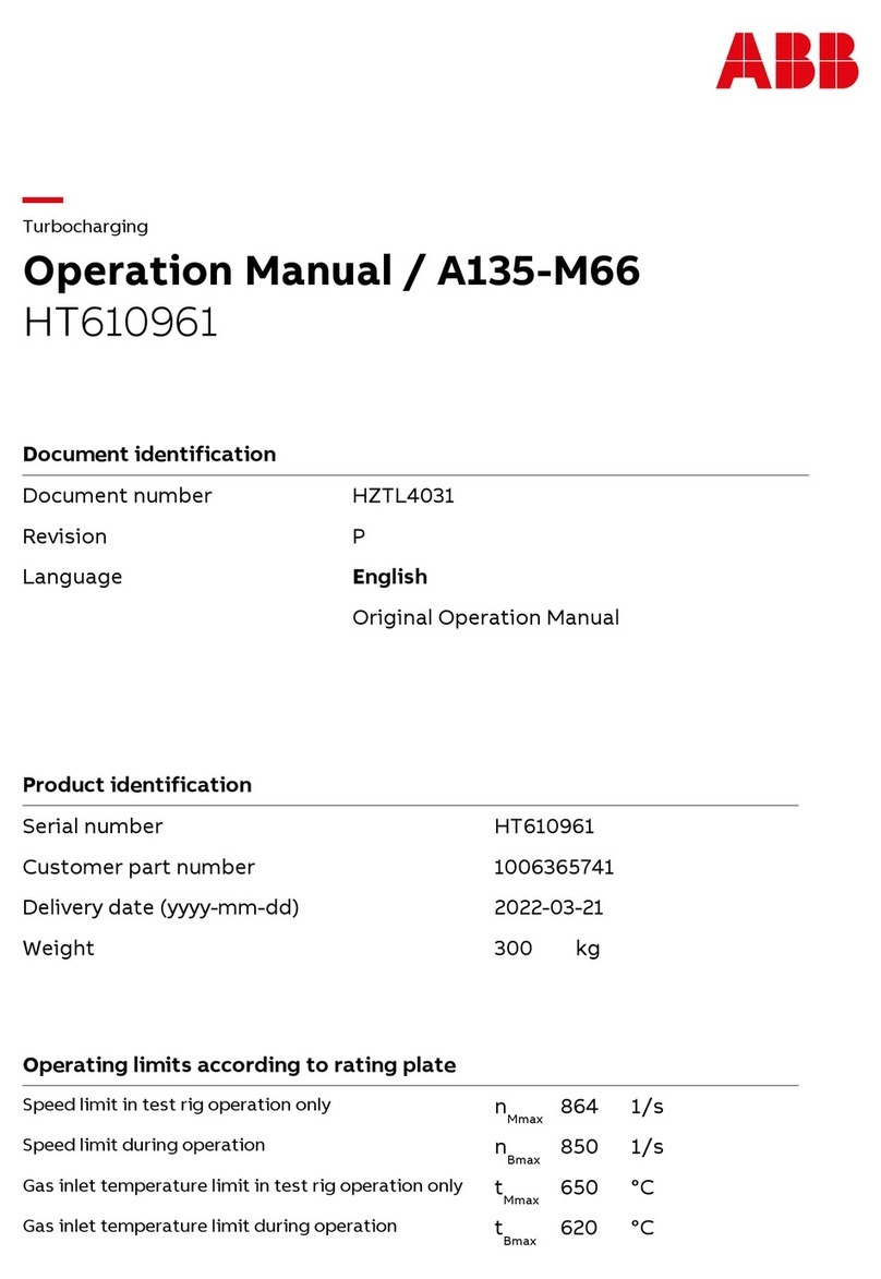
Operation Manual / A165-L37
XAC25131
Document identification
Document number HZTL4034
Revision T
Language English
Original Operation Manual
Product identification
Serial number XAC25131
Customer part number AV65MZ01201
Delivery date (yyyy-mm-dd) 2021-09-16
Weight 2300 kg
Operating limits according to rating plate
Speed limit in test rig operation only nMmax 353 1/s
Speed limit during operation nBmax 338 1/s
Gas inlet temperature limit in test rig operation only tMmax 550 °C
Gas inlet temperature limit during operation tBmax 520 °C


Operation Manual / A100-L
Table of contents
© Copyright 2021 ABB. All rights reserved. HZTL4034_EN Rev.T December 2021
Operation Manual / A100-L
1 Introduction............................................................................................................ 4
1.1 Essential information.................................................................................................... 5
1.2 Registered trademarks................................................................................................. 5
1.3 Layout and function of the turbocharger ................................................................ 6
1.4 Locations of the rating plates.................................................................................... 8
2 Safety ...................................................................................................................... 9
2.1 Introduction ................................................................................................................... 9
2.2 CE conformity................................................................................................................ 9
2.3 Definition of mandatory signs .................................................................................. 10
2.4 Definition of safety instructions .............................................................................. 10
2.5 Intended use ................................................................................................................. 11
2.6 Deflagration on gas engines ..................................................................................... 12
2.7 Warning plates on the turbocharger........................................................................ 13
2.8 Turbocharger rating plate.......................................................................................... 13
2.9 Periodic check of the pressure vessels.................................................................... 15
2.10 Lifting of loads ............................................................................................................. 16
2.11 Prerequisites for operation and maintenance....................................................... 17
2.12 Hazards during operation and maintenance ......................................................... 18
2.13 Safe operation.............................................................................................................. 19
2.14 Safe maintenance ....................................................................................................... 20
3 Removal and installation .................................................................................... 25
3.1 Turbocharger weight ................................................................................................. 25
3.2 Removing the turbocharger...................................................................................... 25
3.3 Installing the turbocharger ....................................................................................... 27
4 Commissioning .................................................................................................... 30
4.1 Oil supply ...................................................................................................................... 30
4.2 Inspection procedures............................................................................................... 30
4.3 Commissioning after taking out of operation....................................................... 32
5 Monitoring during operation.............................................................................. 33
5.1 Oil pressure, oil temperature.................................................................................... 33
5.2 Admissible air inlet temperature ............................................................................. 36
5.3 Turbocharger speed ................................................................................................... 36
5.4 Low pressure measurement at the filter silencer ................................................ 39
6 Operation and service ......................................................................................... 40
6.1 Noise emission ............................................................................................................ 40
6.2 Service work.................................................................................................................. 41
6.3 Expected replacement intervals .............................................................................. 45
6.4 Flexible turbocharger cut-out .................................................................................. 46

Operation Manual / A100-L
Table of contents
© Copyright 2021 ABB. All rights reserved. HZTL4034_EN Rev.T December 2021
6.5 Stopping the engine................................................................................................... 47
7 Periodic maintenance.......................................................................................... 48
7.1 Foreword to maintenance......................................................................................... 48
7.2 Cleaning the filter silencer ........................................................................................ 49
7.3 Changing the filter strip on the filter silencer casing........................................... 51
7.4 Cleaning the compressor during operation .......................................................... 53
7.5 Cleaning the turbine during operation.................................................................... 57
7.6 Draining the gas outlet casing .................................................................................. 61
8 Troubleshooting................................................................................................... 62
8.1 Malfunctions when starting...................................................................................... 62
8.2 Malfunctions during operation ................................................................................ 63
8.3 Surging of the turbocharger..................................................................................... 65
8.4 Malfunctions when stopping.................................................................................... 66
8.5 Speed measurement system.................................................................................... 67
9 Disassembly and assembly................................................................................. 68
9.1 Introduction ................................................................................................................. 68
9.2 Material required......................................................................................................... 69
9.3 Weights of assemblies............................................................................................... 70
9.4 Disassembly and assembly of the filter silencer casing ...................................... 71
9.5 Dismantling the filter silencer .................................................................................. 76
9.6 Dismantling the filter silencer with noise package ............................................. 78
9.7 Dismantling wall insert and diffuser....................................................................... 79
9.8 Axial clearance A prior to disassembly ................................................................... 83
9.9 Dismantling the insulation (≤ A175-L)..................................................................... 84
9.10 Dismantling the gas inlet casing (≤ A175-L) .......................................................... 85
9.11 Dismantling the nozzle ring (≤ A175-L) ................................................................... 86
9.12 Dismantling the gas inlet casing (≥ A180-L).......................................................... 87
9.13 Dismantling the nozzle ring (≥ A180-L)................................................................... 88
9.14 Fitting the nozzle ring (≤ A175-L) ............................................................................. 90
9.15 Fitting the gas inlet casing (≤ A175-L) ..................................................................... 91
9.16 Fitting the insulation (≤ A175-L)............................................................................... 92
9.17 Fitting the nozzle ring (≥ A180-L) ............................................................................ 93
9.18 Fitting the gas inlet casing (≥ A180-L).................................................................... 95
9.19 Axial clearance A after assembly.............................................................................. 96
9.20 Fitting the diffuser ..................................................................................................... 97
9.21 Fitting wall insert ........................................................................................................ 98
9.22 Fitting the filter silencer.......................................................................................... 100
9.23 Fitting the filter silencer with noise package ..................................................... 103
9.24 Table of tightening torques.................................................................................... 105
10 Taking a turbocharger out of operation......................................................... 107
10.1 Possible emergency repairs.................................................................................... 107
10.2 Taking defective turbochargers out of operation ............................................. 108
11 Mothballing the turbocharger........................................................................... 113
Operation Manual / A100-L
Table of contents
© Copyright 2021 ABB. All rights reserved. HZTL4034_EN Rev.T December 2021
11.1 Taking the engine out of operation for up to 12months .................................. 113
11.2 Taking the engine out of operation for more than 12months ......................... 114
12 Material and Disposal........................................................................................ 115
12.1 REACH and RoHS Compliance Declaration For Products .................................. 115
12.2 Disposing of turbocharger components .............................................................. 116
13 Spare parts .......................................................................................................... 117
13.1 Ordering spare parts................................................................................................. 117
13.2 Spare Part - Illustrations........................................................................................... 119
14 Tools .................................................................................................................... 137
Figures................................................................................................................. 138
Tables .................................................................................................................. 140

Operation Manual / A100-L
1 Introduction /
© Copyright 2021 ABB. All rights reserved. HZTL4034_EN Rev.T December 2021
1 Introduction
Page 4 / 141

Operation Manual / A100-L
1 Introduction / 1.1 Essential information
© Copyright 2021 ABB. All rights reserved. HZTL4034_EN Rev.T December 2021
1.1 Essential information
Design variants
This document is valid for different design variants of turbochargers. There may be sections
and descriptions of components that are not relevant for a specific turbocharger variant.
Please contact an ABB Turbocharging Service Station if you have any questions regarding a
design variant (see Contact information at www.abb.com/turbocharging).
Accuracy of illustrations
The illustrations in this document are general in nature and intended for ease of understand-
ing. Differences in detail are therefore possible.
1.2 Registered trademarks
The trademarks of outside companies are used in this document. These are marked with the
® symbol.
Page 5 / 141

Operation Manual / A100-L
1 Introduction / 1.3 Layout and function of the turbocharger
© Copyright 2021 ABB. All rights reserved. HZTL4034_EN Rev.T December 2021
1.3 Layout and function of the turbocharger
Fig.1: Layout and function of the turbocharger
01 Filter silencer 08 Gas inlet casing
02 Thrust bearing 09 Bearing casing
03 Radial plain bearing 10 Diffuser
04 Radial plain bearing 11 Compressor wheel
05 Gas outlet casing 12 Compressor casing
06 Turbine wheel 13 Air-outlet silencer (option)
07 Nozzle ring
Page 6 / 141

Operation Manual / A100-L
1 Introduction / 1.3 Layout and function of the turbocharger
© Copyright 2021 ABB. All rights reserved. HZTL4034_EN Rev.T December 2021
Mode of operation
The turbocharger is a turbomachine and consists of the following main components:
¡Turbine
¡Compressor
These components are installed on a common shaft and form the rotor.
The exhaust gases of the internal combustion engine flow through the gas inlet casing (08)
and the nozzle ring (07) onto the turbine wheel (06). The turbine wheel uses the energy con-
tained in the exhaust gas to drive the rotor and, hence, the compressor wheel(11).
The exhaust gases then reach the atmosphere through the exhaust gas pipe connected to
the gas outlet casing(05).
The compressor wheel (11) sucks in fresh air and presses the compressed air into the cylin-
ders.
The air passes through the filter silencer(01) to the compressor wheel(11). The air then
flows through the diffuser(10) and exits the turbocharger through the compressor cas-
ing(12). An air outlet silencer(13) is optionally available. If installed, this will reduce the
amount of noise generated by the components at the outlet side after the compressor cas-
ing.
The rotor runs in two radial plain bearings(03/04) which are located in the bearing cas-
ing(09) between the compressor and turbine. The axial thrust bearing(02) is located at the
compressor end.
The plain bearings are connected to a central lubricating oil duct which is normally supplied
by the lubricating oil circuit of the engine. The oil outlet always lies at the deepest point of
the bearing casing(09).
The turbocharger is equipped with an oil tank which is integrated in the bearing casing (9).
This oil tank supplies the bearings of the rotor with oil until standstill in the event that a mal-
function of the lubrication oil system causes an emergency stop of the engine.
Page 7 / 141

Operation Manual / A100-L
1 Introduction / 1.4 Locations of the rating plates
© Copyright 2021 ABB. All rights reserved. HZTL4034_EN Rev.T December 2021
1.4 Locations of the rating plates
Fig.2: Locations of the rating plates
One rating plate (01) each is attached on the left and the right side of the turbocharger bear-
ing casing.
Page 8 / 141

Operation Manual / A100-L
2 Safety / 2.1 Introduction
© Copyright 2021 ABB. All rights reserved. HZTL4034_EN Rev.T December 2021
2 Safety
2.1 Introduction
Turbochargers manufactured by ABB reflect the state of the art. The respective safety and
health protection requirements are met. This ensures safe operation of the turbocharger.
Nevertheless, there may be some residual risks during operation of and work on the tur-
bocharger which:
¡are caused by the turbocharger itself or its accessories.
¡are caused by the operating equipment used or supplies and materials.
¡are a consequence of insufficient compliance with safety instructions.
¡are a consequence of insufficient or inappropriate performance of maintenance and in-
spection work.
The operating company is responsible for defining measures that regulate safe access to
and safe handling of the turbocharger.
All instructions contained in this chapter must be observed for safe and trouble-free opera-
tion of the turbocharger and during all work on the turbocharger.
All further safety instructions contained and specifically identified in every chapter of this
Operation Manual (Definition of safety instructions →10) must also be observed.
2.2 CE conformity
Information
ABB turbochargers comply with the Machinery Directive 2006/42/EC and are partly com-
pleted machinery as defined by Article 2 g in this directive.
Page 9 / 141

Operation Manual / A100-L
2 Safety / 2.3 Definition of mandatory signs
© Copyright 2021 ABB. All rights reserved. HZTL4034_EN Rev.T December 2021
2.3 Definition of mandatory signs
To be worn at all times
Protective clothing Safety footwear to protect
against mechanical hazard and
risk of falling
Table1: Personal protective equipment to be worn at all times
To be worn specific to the respective task
Safety glasses Safety goggles
Safety gloves to protect
against
- Mechanical hazard
- Chemical hazard
- Thermal hazard
- Electrical hazard
Respiratory mask to protect
against
- Dusts
- Gases
Safety helmet Ear protection
Table2: Personal protective equipment to be worn specific to the respective task
2.4 Definition of safety instructions
WARNING
Definition of Warning
Non-compliance or inaccurate compliance with working or operating in-
structions indicated by this symbol and the word WARNING can lead to seri-
ous injuries to personnel and even to fatal accidents.
uWarning signs must always be observed.
CAUTION
Definition of Caution
Non-compliance or inaccurate compliance with working or operating in-
structions indicated by this symbol and the word CAUTION can lead to seri-
ous damage to engine or property with grave consequences.
uCaution signs must always be observed.
Page 10 / 141

Operation Manual / A100-L
2 Safety / 2.5 Intended use
© Copyright 2021 ABB. All rights reserved. HZTL4034_EN Rev.T December 2021
2.5 Intended use
Use on internal combustion engines in general
ABB turbochargers are intended for charging internal combustion engines.
The A100-L/A200-L turbochargers are designed for use on 2-stroke engines. These can be
operated with liquid and gaseous fuels.
To ensure compliance with the machinery directive 2006/42/EC when using on gas engines,
the turbocharger must be operated in an engine room classified as "not at risk of explosion".
This is in accordance with the position paper [2] relating to ATEX issued by EUROMOT[1].
The turbocharger supplies the engine with the air volume and associated charging pressure
required for operation.
The turbocharger is solely intended to be operated with a clockwise direction of rotation as
viewed from the turbine end.
The turbocharger is supplied with air from the engine compartment via the filter silencer. If
the air is mixed with cooled exhaust gases via the low-pressure exhaust gas recirculation
(EGR), it must be ensured that these are cleaned as well as possible and that no water
droplets or exhaust gas particles enter the compressor inlet.
The specific operating limits of the turbocharger were determined on the basis of informa-
tion from the enginebuilder about the intended use. These data are given on the rating
plate.
The use of the turbocharger is limited to the specific application released at the time of de-
livery.
ABB accepts no liability and rejects all warranty claims for any non-intended applications.
[1]Euromot = The European Association of Internal Combustion Engine Manufacturers
[2]Directive 94/9/EC concerning equipment and protective systems intended for use in po-
tentially explosive atmospheres (ATEX) The Euromot Position as of November 2003, ATEX
Euromot Position 191103
WARNING
Unapproved operation
Any operation of the turbocharger outside of its operating limits can be haz-
ardous to personnel.
uOnly operate the turbocharger within the operating limits.
uOnly trained personnel must operate the turbocharger.
The intended use of the turbocharger includes compliance with all regulations and condi-
tions. In particular, the following must be observed:
¡Operation Manual
¡Instructions of the enginebuilder
Page 11 / 141

Operation Manual / A100-L
2 Safety / 2.6 Deflagration on gas engines
© Copyright 2021 ABB. All rights reserved. HZTL4034_EN Rev.T December 2021
State of the art
The turbocharger is designed and manufactured according to the state of the art and is safe
to operate.
Perfect condition
The turbocharger must only be used when it is in a technically flawless condition and oper-
ated in compliance with its intended use.
ABB excludes any liability for damage resulting from unauthorized modifications to the tur-
bocharger or improper operation.
2.6 Deflagration on gas engines
ABB turbochargers can tolerate a deflagration with a transient pressure increase of 12bar.
After a deflagration event ABB recommends verifying the following points on the turbochar-
ger:
¡Position of the turbine and compressor casings to the bearing casing
¡Shifting of the bearing casing in relation to the bracket
¡Cracks in casings
If during external inspection anomalies are found or if a particularly strong deflagration
event has taken place, it is also recommended to check the bearings of the turbochargers
before the next start. An ABB Turbocharging Service Station should be instructed to carry
out this inspection.
Page 12 / 141

Operation Manual / A100-L
2 Safety / 2.7 Warning plates on the turbocharger
© Copyright 2021 ABB. All rights reserved. HZTL4034_EN Rev.T December 2021
2.7 Warning plates on the turbocharger
Warning plates are affixed at the following locations:
Fig.3: Warning plate locations
If warning plates are not present in the designated locations or not readable, proceed as fol-
lows:
uOrder new warning plates from ABB Turbocharging Service Stations.
uRemove any warning plates that have become unreadable.
uClean and degrease the areas designated for the warning plates.
uFit new warning plates and remove protective sheets.
Turbochargers supplied to the enginebuilder without insulation must be equipped later with
warning plates on the insulation. This is the responsibility of the enginebuilder.
2.8 Turbocharger rating plate
Fig.4: Rating plate
Page 13 / 141

Operation Manual / A100-L
2 Safety / 2.8 Turbocharger rating plate
© Copyright 2021 ABB. All rights reserved. HZTL4034_EN Rev.T December 2021
Operating limits
01 Turbocharger operating limits at engine overload (110%).
In test rig operation only, unless otherwise agreed with the en-
ginebuilder.
02 Turbocharger operating limits during operation
Recommended replacement intervals of turbocharger components
03 Replacement interval of plain bearings in 1000h
04 Replacement interval of compressor in 1000h
05 Replacement interval of turbine in 1000h
Further data
06 Customer part number
07 Designation for special design
08 Weight of turbocharger in kg
09 Turbocharger type
10 Serial number
11 Year of construction of turbocharger
12 Manufacturing plant
Page 14 / 141

Operation Manual / A100-L
2 Safety / 2.9 Periodic check of the pressure vessels
© Copyright 2021 ABB. All rights reserved. HZTL4034_EN Rev.T December 2021
Explanations regarding the rating plate
The recommended replacement intervals and the corresponding operating limits are jointly
defined with the enginebuilder. This information is specific to the system.
Operation above the indicated values nBmax, tBmax can considerably shorten the recommended
replacement intervals. In such cases ABB recommends contacting the nearest ABB Tur-
bocharging Service Station.
nMmax, tMmax normally apply only when running at overload (110%) during trials on the engine
test bed. These limit values can also be permitted during operation for special applications.
Operation above nMmax and tMmax is not permitted.
Non-observance of the recommended replacement intervals increases the risk of unpredict-
able component failures.
Locations of the rating plates
The locations of the rating plates are defined in the Operation Manual.
2.9 Periodic check of the pressure vessels
The pressure vessels used by ABB Turbocharging, such as those for wet or dry cleaning, are
so-called "simple pressure vessels".
¡The locally applicable legal regulations regarding periodic checks of the pressure vessels
must be observed.
¡The operating company is responsible for the safe operation of the pressure vessel.
WARNING
Danger due to pressure vessels
The operating company must make sure the pressure vessels are in proper
working condition and monitor them. Necessary repair or maintenance work
must be performed promptly, and the required safety measures must be
taken.
uPressure equipment must not be operated if defects are present.
Page 15 / 141

Operation Manual / A100-L
2 Safety / 2.10 Lifting of loads
© Copyright 2021 ABB. All rights reserved. HZTL4034_EN Rev.T December 2021
2.10 Lifting of loads
WARNING
Suspended loads
Loads that are not attached according to regulations can cause injury to
personnel or fatal accidents.
uLoads must always be fastened to properly functional lifting gear with a
sufficient load limit.
uPay attention to the correct attachment of loads on the crane hook.
uPeople must not stand beneath suspended loads.
Wear safety gloves to protect against mechanical hazards.
Wear safety helmet.
Fig.5: Attachment of loads on the crane hook
Fig.6: Attachment angle
If there are two or more suspension points, the attachment angle of 45° must not be ex-
ceeded. This prevents excessive loading due to diagonal pull.
uBefore looping around the components of the turbocharger, let them cool down (max-
imum 80°C).
uAttach components of the turbocharger as described in the respective action steps.
uUse a suitable edge guard if there are sharp edges.
uThe assembly devices must be completely screwed in and must not loosen during use.
uUse assembly devices only for the described applications.
uPut down dismantled components of the turbocharger in such a way that they cannot tip
over.
Page 16 / 141

Operation Manual / A100-L
2 Safety / 2.11 Prerequisites for operation and maintenance
© Copyright 2021 ABB. All rights reserved. HZTL4034_EN Rev.T December 2021
2.11 Prerequisites for operation and maintenance
Responsibility of the operating company
In awareness of its responsibility, the operating company must ensure that only authorised
personnel work on the turbocharger, who:
¡Are versed in the general and locally applicable regulations for occupational safety and
accident prevention
¡Are equipped with the prescribed personal protective equipment
¡Have read and understood the Operation Manual
¡Have been instructed in the use of the turbocharger.
The safety-conscious work of the personnel and adherence to the Operation Manual must be
checked periodically.
Suitable working materials and personal protective equipment must be kept in a perfect
condition.
Only authorised personnel may remain in the vicinity of the turbocharger when the engine is
running.
Competence of personnel
The turbocharger must only be operated and serviced by trained and authorised personnel.
Basic mechanical training is a prerequisite.
Modifications to the turbocharger
Modifications to the turbocharger must be approved by ABB.
WARNING
Use original parts
Operation of the turbocharger with non-original parts can impair the safety
of the turbocharger and can cause serious damage to property and injury to
personnel.
uOnly use original parts from ABB.
Original parts and accessories are specially designed for ABB turbochargers.
ABB accepts no liability for any damage resulting from the use of non-original parts and cor-
responding accessories.
Page 17 / 141

Operation Manual / A100-L
2 Safety / 2.12 Hazards during operation and maintenance
© Copyright 2021 ABB. All rights reserved. HZTL4034_EN Rev.T December 2021
2.12 Hazards during operation and maintenance
Noise hazards
The turbocharger's noise emission is influenced by its installation and operating conditions.
A noise level exceeding 85 dB(A) is harmful.
WARNING
Noise hazards
Exposure to noise can harm the hearing system, impair health and the psy-
chological state and may lead to lack of attention and irritation.
uWhen the engine is running, always wear ear protection.
uAlways wear ear protection if the sound pressure level exceeds 85 dB(A).
Wear ear protection.
Hazards due to hot surfaces
Surfaces of the turbocharger, attached parts and operating fluids (lubricating oil) get hot
during operation. The surface temperature depends on the efficacy of the existing insula-
tion. The temperature may rise to a level that can cause burns.
WARNING
Danger of burns
Touching hot surfaces or contact with hot operating fluids can cause burns.
uDo not touch hot surfaces. Observe the warning plate on the turbochar-
ger.
uWear heat-resistant safety gloves and protective clothing.
uWait for the turbocharger to cool down before carrying out any work.
Wear safety gloves to protect against thermal hazards.
Page 18 / 141
This manual suits for next models
1
Table of contents
Other ABB Batteries Charger manuals
Popular Batteries Charger manuals by other brands

ProMariner
ProMariner ProNautic 2420P Operation instructions

Vetus
Vetus BCS1225 Operation manual and installation instructions

Bosch
Bosch BC1880 Operating and safety instructions

KUSSMAUL
KUSSMAUL 091-31-12 instruction manual

Hama
Hama 00115491 operating instructions

Stanley
Stanley GBCPRO instruction manual