ABB HVC 100C User manual

—
USER MANUAL
HVC 100C / HVC 150C with
Depot Charge box
User and Operation Manual
Version 0.6

Document: v0.6 / Document No.: 6AGA000008-0102-EN | Date: 22-05-2019 Page 2of 23
Notice
This document contains information about one or more ABB products and may include a descrip-
tion of or a reference to one or more standards that may be generally relevant to the ABB products.
The presence of any such description of a standard or reference to a standard is not a representa-
tion that all of the ABB products referenced in this document support all of the features of the de-
scribed or referenced standard. In order to determine the specific features supported by a particu-
lar ABB product, the reader should consult the product specifications for the particular ABB
product.
ABB may have one or more patents or pending patent applications protecting the intellectual prop-
erty in the ABB products described in this document.
The information in this document is subject to change without notice and should not be construed
as a commitment by ABB. ABB assumes no responsibility for any errors that may appear in this doc-
ument.
In no event shall ABB be liable for direct, indirect, special, incidental or consequential damages of
any nature or kind arising from the use of this document, nor shall ABB be liable for incidental or
consequential damages arising from use of any software or hardware described in this document.
This document and parts thereof must not be reproduced or copied without written permission
from ABB, and the contents thereof must not be imparted to a third party nor used for any unau-
thorized purpose.
Copyrights
All rights to copyrights, registered trademarks, and trademarks reside with their respective
owners.
Copyright © 2019 ABB.
All rights reserved.

Document: v0.6 / Document No.: 6AGA000008-0102-EN | Date: 22-05-2019 Page 3of 23
Version control
Ver-
sion
Date
Remarks
V0.1-0.3
01-12-2018
Released next version with pilot feedback
V0.4
01-02-2019
Released next version with updated info sequential charging
V0.5
01-05-2019
Updated sequential charging information
V0.6
22-05-2019
Updated document nr and format

Document: v0.6 / Document No.: 6AGA000008-0102-EN | Date: 22-05-2019 Page 4of 23
Contents
Glossary...............................................................................................................................................................5
1Introduction ...................................................................................................................................................6
1.1 Preface................................................................................................................................................................ 6
1.2 Intended use of this document..................................................................................................................... 6
1.3 Intended use of the charger .......................................................................................................................... 6
1.4 Owner responsibilities.................................................................................................................................... 7
1.5 Signs.................................................................................................................................................................... 7
1.6 Safety regulations............................................................................................................................................ 9
2Description of the product.........................................................................................................................10
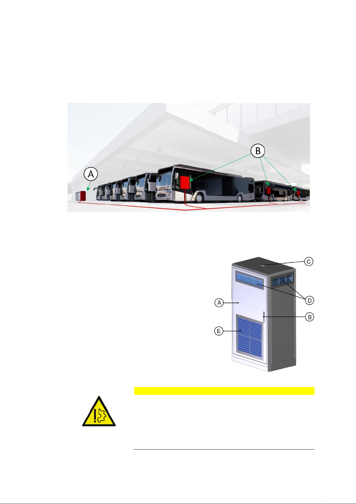
2.1 Overview of the system................................................................................................................................ 10
2.2 Charge cabinet................................................................................................................................................ 10
2.3 Depot charge box............................................................................................................................................11
2.4 Charger configurations ................................................................................................................................ 12
2.5 Authorization to charge................................................................................................................................ 12
3Charging instruction................................................................................................................................... 13
3.1 Charging with 1 Depot Charge Box............................................................................................................ 13
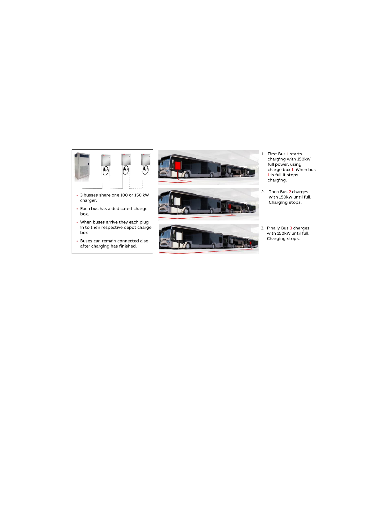
3.2 Charging with 2 or 3 Depot Charge Boxes ............................................................................................... 13
3.3 Emergency stop.............................................................................................................................................. 14
4Operator Instructions ................................................................................................................................. 15
4.1 Cleaning of the cabinet and Depot charge box ...................................................................................... 15
4.2 Preventive maintenance................................................................................................................................ 15
4.2.1 Service inspection of the cabinets........................................................................................... 15
4.2.2 Emergency stop inspection ....................................................................................................... 16
4.2.3 Special inspections...................................................................................................................... 16
4.3 Problem resolving .......................................................................................................................................... 16
4.3.1 Overview of the Power Cabinet................................................................................................. 16
4.3.2 Overview of the Depot charge box............................................................................................17
4.3.3 Component overview Power Cabinet ...................................................................................... 18
4.3.4 Component overview Depot Charge Box................................................................................ 18
4.4 Technical functioning.................................................................................................................................... 19
4.4.1 Normal operation......................................................................................................................... 19
4.4.2 Switch the charger system on/off ........................................................................................... 19
4.4.3 Switch the depot box .................................................................................................................. 19
5Contact information ................................................................................................................................... 21

Document: v0.6 / Document No.: 6AGA000008-0102-EN | Date: 22-05-2019 Page 5of 23
Glossary
CCS
Combined Charging System. A universal AC and
DC charging system, also referred to as
‘Combo’.
DC
Direct Current.
EV
Electric Vehicle.
Owner
The legal owner of the charger.
OCPP
Open Charge Point Protocol. Open standard for
communication with charge stations.
PE
Protective Earth.
RCBO
Residual-current Circuit Breaker with Overload
protection. Breaks the connection if a residual
current or overload is detected.
RCD
Residual Current Device. Breaks the connection
if a residual current is detected.
Site operator
Person or company that controls the charge sta-
tion. The site operator can be the owner, but not
necessarily.
User
The driver of an EV who uses the charge station.

Document: v0.6 / Document No.: 6AGA000008-0102-EN | Date: 22-05-2019 Page 6of 23
1Introduction
1.1 Preface
The HVC-C product line is the new ABB solution for Overnight Charging of Heavy Vehi-
cles. The product line allows 100kW and 150kW charging with up to 3 charging outlets
per one charger. The charging of the vehicles is done sequentially following the first
come, first serve principle.
This manual describes the general usage and daily operation instructions of the HVC-C
product family.
1.2 Intended use of this document
This document serves:
•As a reference for site operators who are responsible for the charger’s operation
on site, performing daily inspection and maintenance activities and who are able
to perform simple trouble shooting activities, after instruction of a certified ABB
technician.
•As a reference to the operator’s customers, the EV drivers who will mainly use
the pictograms and texts on the display of the charger. The user interface design
was thoroughly evaluated with user groups to optimize understandability and to
get the best user experience. Besides the screens needed for the charging pro-
cess, the interface has help screens available to provide additional information.
1.3 Intended use of the charger
The HVC-C product is a stand-alone DC high power charger for electric buses and trucks.
The outlets of the charger must not be used to charge any other equipment than electric
vehicles compatible with the supported charging standards.

Document: v0.6 / Document No.: 6AGA000008-0102-EN | Date: 22-05-2019 Page 7of 23
1.4 Owner responsibilities
The owner and site operator are required:
•To operate the charge station with the protective devices installed, and to make
sure all protective devices are correctly installed after carrying out installation or
maintenance.
•To write an emergency plan that instructs people what to do in case of emer-
gency.
•To prepare the site where the charge station will be installed, according to the re-
quirements described in this guide.
•To make sure that there is enough space around the charger to carry out mainte-
nance work.
•To appoint a person responsible for the safe operation of the charge station and
for the coordination of all work. This person should be properly instructed by
ABB or an ABB trained service partner.
The owner is cautioned that changes or modifications not expressly approved by ABB
could void the owner’s authority to operate the equipment or ABB’s warranty.
Neither ABB nor its affiliates shall be liable to the purchaser of this product or third par-
ties for damages, losses, costs or expenses incurred by purchaser or third parties as a
result of: an accident, misuse or abuse of this product, or unauthorized modifications,
repairs or alterations to this product, or failure to strictly comply ABB operating and
maintenance instructions.
1.5 Signs
The following signs are used on the equipment and in this manual:
DANGER
Hazardous voltage
Identifies a hazard that could result in severe injury or death
through electrocution.
WARNING
Various
Identifies a hazard that could result in severe injury or death.
WARNING
Rotating parts
Identifies a hazard that could result in injury due to the pres-
ence of rotating or moving parts.

Document: v0.6 / Document No.: 6AGA000008-0102-EN | Date: 22-05-2019 Page 8of 23
WARNING
Pinch Hazard
Identifies a hazard that could result in injuries, in which
some body parts are pinched or crushed.
CAUTION
Various
Identifies a hazard that could result in damage to the ma-
chine, other equipment, and/or environmental pollution
NOTICE
Contains remarks, suggestions or advice.

Document: v0.6 / Document No.: 6AGA000008-0102-EN | Date: 22-05-2019 Page 9of 23
1.6 Safety regulations
WARNING
If a charge outlet is damaged, take the following steps:
1. Do not use the damaged charge outlet.
2. Contact the owner / site operator.
WARNING
If there is an emergency
1. Push the emergency stop.
2. Contact the owner / site operator.
3. Act according to the emergency procedure of the
owner / site operator.
WARNING
Operation after damage or accidents
•If there is a fire in or nearby the charger;
•If the charger was immersed in water, or any other
fluid;
•If the charger is damaged in any way.
Do not use the charger. Contact the owner / site operator.
NOTICE
When connecting or disconnecting a connector
1. Handle cables and connectors with care. Do not drop
the cables or connectors. Place them back in their re-
spective holders.
2. Only insert a connector into a suitable car inlet.
Never use excessive force.
NOTICE
Connector locked
The DC connector will be locked during the charging process
to prevent it from dropping or being pulled out. Do not apply
a force on the cable during the charging process as it might
damage the inlet and locking mechanism in your car or dam-
age the charger.

Document: v0.6 / Document No.: 6AGA000008-0102-EN | Date: 22-05-2019 Page 10 of 23
2Description of the product
2.1 Overview of the system
A. Charge cabinet 100-150kW
B. Depot charge boxes (up to 3 per charger with sequential charging)
2.2 Charge cabinet
A. Door
B. Door handle / lock
C. 3G Antenna
D. Air inlets (also on the left and back side)
E. Air outlet
CAUTION
The Power Cabinet has air inlets (D) and an air outlet (E) to control
the temperature inside the cabinet. Do not install or place any ob-
jects near or against these air inlets and outlet. If necessary, take
precautions to prevent snow or any other objects from blocking the
air inlets and outlet.

Document: v0.6 / Document No.: 6AGA000008-0102-EN | Date: 22-05-2019 Page 11 of 23
2.3 Depot charge box
The user operated components are indicated on below:
A. LED beacon
B. Emergency button
C. Stop button
D. Door handle & lock
E. Connector holder
F. CCS charge cable
G. External connections
Overview LED colors and state:

Document: v0.6 / Document No.: 6AGA000008-0102-EN | Date: 22-05-2019 Page 12 of 23
2.4 Charger configurations
The charger is built up with a modular architecture. Supported charging standards are:
Product
Description
HVC-100C CE
100kW charge cabinet configuration with 1-3 Depot charge boxes,
supporting CCS-2 with CE certification
HVC-150C CE
150kW charge cabinet configuration with 1-3 Depot charge boxes,
supporting CCS-2 with CE certification
HVC-100C UL
100kW charge cabinet configuration with 1-3 Depot charge boxes,
supporting CCS-1 with UL certification
HVC-150C UL
150kW charge cabinet configuration with 1-3 Depot charge boxes,
supporting CCS-1 with UL certification
For each product configuration (100 or 150kW, CE or UL) it is possible to connect 1 up to
3 Depot Charge boxes.
2.5 Authorization to charge
The standard setting is without authorization. This means that every vehicle supporting
CCS is able and allowed to start a charge session. Operating a charger with authoriza-
tion requires a subscription to a back office. Authorization can only be done based on
the Vehicle ID and requires a subscription to a back office. This product does not sup-
port a RFID reader.

Document: v0.6 / Document No.: 6AGA000008-0102-EN | Date: 22-05-2019 Page 13 of 23
3Charging instruction
3.1 Charging with 1 Depot Charge Box
Start charging:
1. Park the electric vehicle with the charge inlet within reach of the connector.
2. Turn off the electric vehicle.
3. Connect the charger’s connector to the vehicle’s charge inlet.
4. The charger will automatically start to charge the vehicle after the preparation
phase, and will indicate the progress by the LED state (see 2.3).
Stop charging:
5. The charge session will continue to charge the bus until the charge session is
stopped.
6. The charge session can be stopped manually by either pushing the stop button
on the depot charge box or the stop button on the bus (not available on every
bus).
7. Charging stops
8. The connector is unlocked by the vehicle for CCS when the Depot box beacon
light changes color to green
9. Take the connector out of the vehicle and put it back in the connector holder on
the depot charge box.
3.2 Charging with 2 or 3 Depot Charge Boxes
The main principle of the sequential charging is to complete the bulk charge for all the
buses that are connected to the charger, before they leave the depot in the morning. The
sequence will be based on the principle first come, first serve.
When the bulk charge is complete the charger will automatically continue with the pre-
conditioning. The charger will follow the same sequence as during bulk charging (first
come, first serve) in a continuous time loop of 20 minutes per bus.
Start charging:
1. Park the electric vehicle with the charge inlet within reach of the connector.
2. Turn off the electric vehicle.
3. Connect the charger’s connector to the vehicle’s charge inlet.
4. When there is no other bus already connected that requires bulk charging:
•The charger will automatically start to charge the vehicle after the prepa-
ration phase, and will indicate the progress by the LED state (see 2.3).
5. When there is another bus already connected that is being charged:
•The LED state will turn to green and start blinking until the other charge
sessions are complete. After completing the other bulk charge session(s)
the charger will automatically start to charge the vehicle after the prepa-
ration phase, and will indicate the progress by the LED state (see 2.3).
6. When all buses completed the bulk charge (SOC > 95% OR Bulkchargecomplet
flag = true (initiated by the bus)) the preconditioning will start, following the
same sequence as the bulk charge with a time interval of 20 min between each
bus.

Document: v0.6 / Document No.: 6AGA000008-0102-EN | Date: 22-05-2019 Page 14 of 23
Stop charging:
7. If there is another bus connected to the charger that requires bulk charging the
charger will stop the preconditioning and automatically switch to the bus that
requires bulk charging.
8. The preconditioning will continue in a 20 min loop between all the connected bus
until the charge session is stopped. This can be done manually by either pushing
the stop button on the depot charge box or the stop button on the bus (not
available on every bus).
9. If the stop button is pressed and there is another vehicle connected that requires
bulk charge or preconditioning, the charging will automatically switch to the next
bus in line and continue the charge session.
10. When the charging is stopped, the connector is unlocked by the vehicle for CCS.
11. Take the connector out of the vehicle and put it back in the connector holder on
the depot charge box.
NOTICE
Session end
Charging will stop without user interaction:
•When the EV indicates to the charger that charging is
completed.
•When the charger completed the bulk charge.
If the battery is not full, a new charge session can be started.
NOTICE
Stop by emergency button
The charger stops the charge session when the emergency
stop is pushed. Only push the emergency stop if there is an
emergency!
3.3 Emergency stop
If there is an emergency:
1. Push the emergency stop button.
The Charger stops the operation and the LED beacon from each connected Depot
Charge Box will be red.
2. Contact the Site operator.
NOTICE
Emergency button is pressed accidentally
If the emergency stop button is accidentally pushed:
1. Verify that the situation is safe.
2. Pull the emergency out.
•The emergency button is released and the charger is
reactivated.
•After a few seconds the charger returns to normal op-
eration.

Document: v0.6 / Document No.: 6AGA000008-0102-EN | Date: 22-05-2019 Page 15 of 23
4Operator Instructions
4.1 Cleaning of the cabinet and Depot charge box
DANGER
Electrical components
•Do not apply high-pressure water jets. Water may leak into the cabinet.
•Only use cleaning agents with a pH value between 6 and 8.
•Do not use cleaning agents with abrasive components.
•Do not use abrasive tools.
The cabinet of the Power Cabinet and Depot charge box is made from powder coated high
quality stainless steel. The coating must be kept in good condition.
Clean the Charger three times a year in the following way:
•Remove rough dirt by rinsing with low-pressure tap water.
•Apply a neutral or weak alkaline cleaning solution and let it soak.
•Remove dirt by hand with a non-woven nylon hand pad.
•Rinse thoroughly with tap water.
•Optionally, apply wax on the front for extra protection and gloss.
•Check the coating on damage.
NOTICE
Rust forming
When the charger is placed in a corrosion sensitive environment, the forming of
superficial rust is possible on the welding points on the side grills. This rust is
merely visual, there is no possibility this will form a risk on the cabinets integrity.
The rust can be removed with the cleaning procedure above. To prevent the rust
from reappearing; prime the areas with a transparent or color-like priming finish.
4.2 Preventive maintenance
Maintenance is done according the maintenance schedule. The charger must be inspected and
serviced yearly by a certified technician.
4.2.1 Service inspection of the cabinets
The following points must be checked regularly:
•Internal RCDs and RCBOs need to be tested on correct functioning on a regular basis.
During the yearly maintenance round that is advised to be executed by a certified ABB
technician, this will be checked.
•Powder coating: look for damage, cracks or ruptures.

Document: v0.6 / Document No.: 6AGA000008-0102-EN | Date: 22-05-2019 Page 16 of 23
4.2.2 Emergency stop inspection
It is advised to test the emergency button every time someone of the operator or service or-
ganization visits the location of the charger. This test needs to be done at least once a year e.g.
during a preventive maintenance round.
Test only when the charger is in idle mode and ready to charge:
1. Press the emergency button.
•The indicator light (beacon) will turn red.
2. Reset the emergency button by turning the knob clockwise.
•After a few moments, the charger returns to its idle state.
4.2.3 Special inspections
In the following cases the charger must be checked by ABB service personnel before further
use:
•If it was struck by lightning.
•If it is damaged due to an accident or fire.
•If its location has been flooded.
4.3 Problem resolving
The site operator or helpdesk is the first response to a customer call. The helpdesk can remo-
tely solve simple problems for the customer.
In special cases the site operator with knowledge of the charger can be asked by ABB support
to report about the status of some internal components of the charger. Therefore a brief
description of the position and function of these components is described on the next pages.
4.3.1 Overview of the Power Cabinet
ADoor
BDoor handle / lock (per Power Cabinet
Unique system key)
WARNING
Do not open the Power Cabinet door if you are not familiar with working with high
voltage and high current.

Document: v0.6 / Document No.: 6AGA000008-0102-EN | Date: 22-05-2019 Page 17 of 23
4.3.2 Overview of the Depot charge box
AFront door Depot charge box
BDoor handle / lock (per depot box
Unique system key)
WARNING
Do not open the Depot charge box door if you are not familiar with working with
high voltage and high current.

Document: v0.6 / Document No.: 6AGA000008-0102-EN | Date: 22-05-2019 Page 18 of 23
4.3.3 Component overview Power Cabinet
The main components as can be seen with an open front door:
AMain switch
BMCB (Q17) AC power supply for ACM
CRCD (Q13) control
DRCD (Q12) redundant control
EDisplay
4.3.4 Component overview Depot Charge Box
The main components as can be seen with an open front door:
ASPD (F2) AC Power Supply
BMCB (F1) AC Power Supply
CFuse (F3,F4) DC Circuit
DSPD (F5) DC Power Circuit

Document: v0.6 / Document No.: 6AGA000008-0102-EN | Date: 22-05-2019 Page 19 of 23
4.4 Technical functioning
4.4.1 Normal operation
Normal positions of the different switches and breakers when the charger is in operation (idle;
not charging):
Power Cabinet
•Main switch (A): Vertical (“1”)
•MCB (Q17) AC power supply for ACM (B): up
•RCD (Q13) control (C): up
•RCD (Q12) redundant control (D): up
Depot Charge Box
•SPD (F2) AC Power Supply: green
•MCB (F1) AC Power Supply: up
•Fuse (F3,F4) DC Precharge Circuit: not blown
•SPD (F5) DC Power Circuit: green
4.4.2 Switch the charger system on/off
In case it is necessary to switch off the charger system, this can be done by turning off the
main switch (A in Power Cabinet, see section
Component overview Power Cabinet
on page 18):
1. Open the front door.
2. Locate the main switch (A).
3. Turn the handle counterclockwise to the horizontal position, marked with “0”.
WARNING
Switching off the charger does not switch off Depot Box. Each box has its own
power supply. To turn off the Depot Box see chapter 4.4.3
To switch the charger back on, turn the handle clockwise to the vertical position, marked with
“1”. After about a minute the indicator light (beacon) will turn green.
NOTICE
Operating the main switch is quite arduous. Use both hands if needed and be
careful not to injure yourself.
4.4.3 Switch the depot box
In case it is necessary to switch off the depot box, this can be done by turning off the main
switch:
1. Open the front door.
2. Locate the main switch (B).
3. Move the MCB switch down (OFF position). Green painting on the switch should be
visible

Document: v0.6 / Document No.: 6AGA000008-0102-EN | Date: 22-05-2019 Page 20 of 23
NOTICE
Every box has its own power supply line.
Following procedure should be performed for every box which should be powered
off.
Other manuals for HVC 100C
1
This manual suits for next models
1
Table of contents
Other ABB Batteries Charger manuals