Important safety information
Electric shock hazard! Disconnect and ISOLATE the Drive before
attempting any work on it.
High voltages are present at the terminals and within the drive for up
to 10 minutes after disconnection of the electrical supply. Always
ensure by using a suitable multimeter that no voltage is present on
any drive power terminals prior to commencing any work.
This variable speed drive product (Drive) is intended for professional
incorporation into complete equipment or systems as part of a fixed
installation. If installed incorrectly it may present a safety hazard. The
Drive uses high voltages and currents, carries a high level of stored
electrical energy, and is used to control mechanical plant that may
cause injury. Close attention is required to system design and
electrical installation to avoid hazards in either normal operation or in
the event of equipment malfunction.
Only qualified electricians are allowed to install and maintain this
product.
The entry of conductive or flammable foreign bodies should be
prevented. Flammable material should not be placed close to the
drive.
General safety instructions
WARNING! ACS260 units may become damaged if
operated without a suitable heatsink. Do not operate
the unit without providing suitable heatsink capacity
for the drive and application requirement.
• ACS260 Power Modules must be mounted onto a suitable flat
metallic surface with sufficiently low thermal resistance to allow
dissipation of the heat produced.
• Surface flatness must be =<+ / - 0.2mm over the mounting area
• The chosen mounting location must ensure the unit is not subject
to vibration levels in excess of the limits specified in section
vibration.
• Units should be mounted only using the integral mounting holes.
• The ACS260 must be installed in a pollution degree 1 or 2
environment only.
• Ensure that the ambient air temperature range around the unit
during operation does not exceed the permissible limits given in
User Manual section Technical Data.
• Do not mount flammable material close to the ACS260.
• Units may be mounted in any orientation.
Type designation key Definition
Sample type code: ACS260-04-02A2-4
Dimension and Mounting
Frame size R1
Frame size R2
Electric connection
Frame size R1 and R2
Start-up
When delivered, ACS260 is pre-programmed to run from remote
inputs wired to the terminal strip. This default digital input
configuration provides a general purpose I/O setup with a hard-wired
start / stop enable, forward / reverse input and a selection between
an analog speed reference or preset speed input.
Parameter 1103 = 0 defines control from the terminal strip (for Keypad
Control 1103 =1) and Parameter 9902 = 0 sets up the configuration for
the inputs and outputs as shown below.
1. The drive is to run PM motor (9903=2) as default. Changing 9903=0
when induction motor is connected.
2. Connect a control switch between the control terminals 1 and 2 and
ensure that the contact is open (drive disabled). Connect a
potentiometer (1kΩmin to 10 kΩmax) between terminals 5 and 7
with the wiper to terminal 6 of the control terminal. With the
potentiometer set to zero, switch on the supply to the drive.
3. The status LED is slow flashing green and a connected RCRP-02
Keypad will display STOP. Close the control switch, terminals 1-2,
the drive is now ‘enabled’ and the output frequency speed are
controlled by the potentiometer. The status LED will change to
constant on green.
4. The display shows zero speed in Hertz as H 0.0. with the
potentiometer turned to minimum. If the display is not showing H,
change it with the navigate key. Adjust the speed using the
potentiometer, the motor will accelerate to the speed set by the
potentiometer up to the value set in parameter 2008 (maximum
frequency limit.)
5. Stop the drive by opening the control switch (terminal 1-2).
Default I/O connection for standard type
Remote Keypad RCRP-02
NOTE: For keypad control set parameter 1103=1 and 9902 to the
desired I/O configuration. Terminal 1 and 2 must be connected to
enable ACS260.
Keypad Operation
Setting parameter 1103 to a value of 1 enables keypad mode with
forward direction only, while a value of 2 enables keypad mode with
forward and reverse rotation.
Set parameter 1100 to 1 or 3 to enable the drive to start from the
previous set keypad reference speed.
While the drive is stopped, press the STOP key. The value of the digital
potentiometer will be displayed, indicating the target speed. Use the
UP and DOWN keys to select the required target speed.
Press the STOP key to return to the real time display showing STOP or
press the START key to start the drive ramping up to the target speed.
To reverse direction, press the START key again.
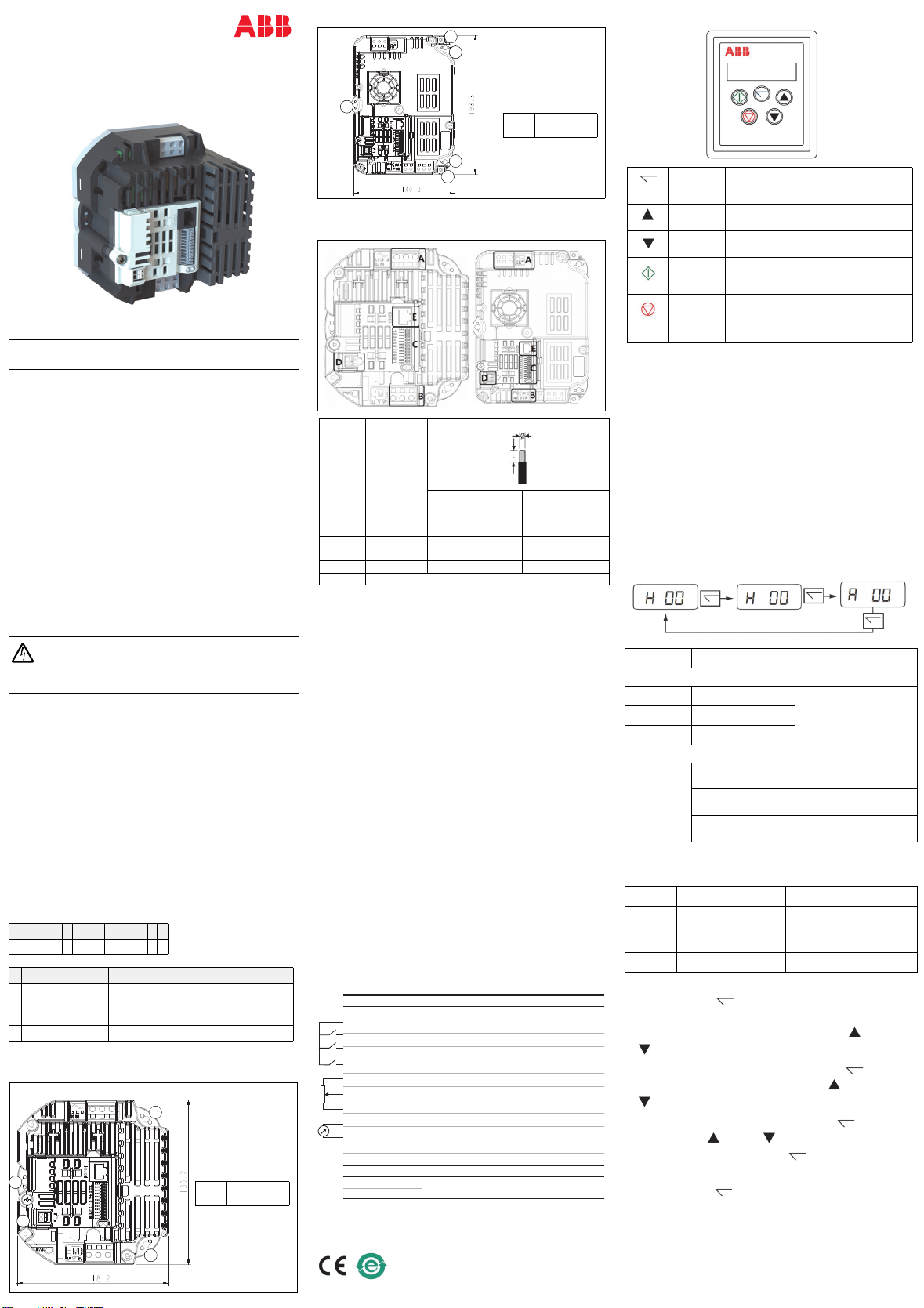
Keypad Display Screens
Prior to operation the keypad will show STOP, pressing the STOP key
allows setting the preset speed on the display (H x.x) While in
operation the following displays can be accessed by briefly pressing
the Navigate Key.
Accessing Parameters and Program Navigation
The parameters are arranged in Groups according the to the following
structure.
Parameter Navigation
• Press and hold the NAVIGATE key for more than 1 second
when the drive is displaying STOP. The display changes to PAr 5,
indicating the short (S) parameters group. Use the ( UP) and
(DOWN) keys to select between the S, Lor Aparameter groups.
• To enter a parameter group, press and release the (Navigate)
key while the group letter is flashing. Use the (UP) and
(DOWN) keys to change to the desired parameter number.
• To change parameter values, press and hold the (Navigate)
key then use the (UP) and (DOWN) keys to change to the
required value. Press and release the (Navigate) key once
more to store the change.
• Press and hold the (Navigate) key for more than 1 second to
return to real-time mode. The display shows STOP if the drive is
stopped or the real-time information (e.g. speed, current or power)
if the drive is running.
• To access Read Only Parameters, navigate to PAr L Group and
scroll to Parameter 0000, then press and release the navigate key.
Segment A B C
ACS260 - 04 - 02A2 - 4
Code Description
AConstruction 04 = Module
BCurrent rating For example, 02A2 refers to a nominal
output current of 2.2 A.
CVoltage rating 4 = 3-phase 380...480 V
—
ABB MACHINERY DRIVES
ACS260-04 Component Drive
Quick installation and start-up guide
Use 3 x M4 (No. 8)
bolts or screws,
tightening torque:
4Nm / 3ft-lb
Depth: 74mm
Weight: 0.7kg,
1.54lb
1Mountinghole
2PE
1
2
1
1
Location Purpose
ØL
AIncoming
Power 1.5mm2/ AWG 14 Max 5 – 6mm / 0.2in
BMotor 1.5mm2/ AWG 14 Max 5 – 6mm / 0.2in
CControl
Terminals
0.5mm2/ AWG 20
Max 6 – 7mm / 0.25in
DOutput Relay 1.5mm2/ AWG 14 Max 8 – 9mm / 0.3in
ERJ45 Serial : Warning! Not Ethernet!
Use 3 x M4 (No. 8)
bolts or screws,
tightening torque:
4Nm / 3ft-lb
Depth:89mm
Weight:1.3kg, 2.87lb
1Mountinghole
2PE
1
1
1
2
2
8IVQMREPW -RWXVYGXMSR
(MKMXEP-3GSRRIGXMSR
:C398 %Y\MPMEV]ZSPXEKISYXTYX:('
(- (MKMXEP-RTYX7XST演漕7XEVX演漕
(- (MKMXEP-RTYX*SV[EVH6IZIVWEP演漕
(-%- (-%-TVIWIXWTIIH演漕 %REPSKWTIIHVIJIVIRGI演漕
:C398 :SPXEKIVIJIVIRGI:('
%-(- %-(-WTIIHVIJIVIRGI:
%+2( %REPSKMRTYXKVSYRH
%3(3 %REPSKSYXTYX(MKMXEPSYXTYX
+2( +VSYRH
1SHFYW689
1SHFYW689
6IPE]3YX
60% '31 %'7(VMZIVIEH]
60& 23
Markings
The applicable markings are shown on the type label of the product.
CE China RoHS
NAVIGATE Used to display real-time information, to
access and exit parameter edit mode and to
store parameter changes.
UP Increase speed in real-time mode or scroll
through values in parameter edit mode.
DOWN Decrease speed in real-time mode or scroll
through values in parameter edit mode.
START When in keypad mode, the button is used to
start a stopped drive or to reverse the
direction of rotation.
STOP In normal application, when in Keypad
mode, this button is used to stop a running
drive. If in trip mode, the key is used to reset
the drive.
STOP Drive power applied and no Enable or Run signal
Drive Running
H 0.0. Output Frequency (Hz) Press Navigate to select
display
Press again to cycle display
A 0.0. Motor Current (Amps)
P 0.0. Motor Power (kW)
Drive Running, Speed Reference = 0
Stndby
Enable / disable switch open drive will decelerate to
stop and display shows STOP
A zero reference and enable/disable closed the
display with show H 0.0 (0.0Hz)
60 seconds at zero speed drive standby mode Stndby
waiting for a speed reference
PAR 5 Short Parameter Group Basic Setup Parameters
PAR L Long Parameter Group Sequential List all Parameters
Access to Display Group
PAR A Advanced Group Advanced Motor Control
0000 Read Only Display Group Parameter 0000 Par L Group
3AXD50000672103 Rev A 2020-12-18


