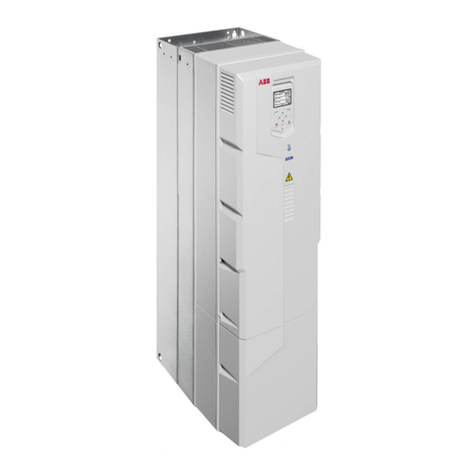
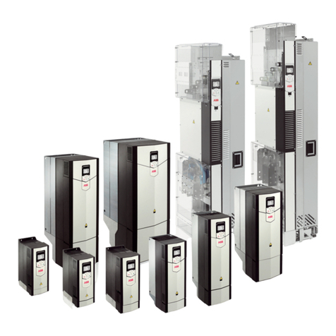
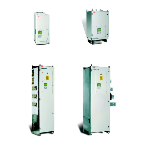
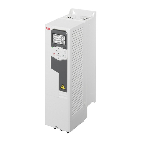
ABB ACH550 series User manual

ACH550
Installation, Operation and Maintenance Manual (I, O & M)
ACH550-UH HVAC Drives (1…550 HP)
ACH550-BCR/BDR/VCR/VDR E-Clipse Bypass Drives (1…400 HP)
ACH550-PCR/PDR Packaged Drives with Disconnect (1…550 HP)

2 ACH550 Installation, Operation and Maintenance Manual
Safety
Safety
Use of warnings and notes
There are two types of safety instructions throughout this manual:
• Notes draw attention to a particular condition or fact, or give information on a
subject.
• Warnings caution you about conditions which can result in serious injury or death
and/or damage to the equipment. They also tell you how to avoid the danger. The
warning symbols are used as follows:
Electricity warning warns of hazards
from electricity which can cause
physical injury and/or damage to the
equipment.
•WARNING! The ACH550 adjustable speed
AC drive should ONLY be installed by a
qualified electrician.
•WARNING! Even when the motor is
stopped, dangerous voltage is present at the
power circuit terminals U1, V1, W1 (L1, L2,
L3) and U2, V2, W2 (T1, T2 T3) and,
depending on the frame size, UDC+ and
UDC-, or BRK+ and BRK-.
•WARNING! Dangerous voltage is present
when input power is connected. After
disconnecting the supply, wait at least 5
minutes (to let the intermediate circuit
capacitors discharge) before removing the
cover.
•WARNING! Even when power is switched
off from the input terminals of the ACH550,
there may be dangerous voltage (from
external sources) on the terminals of the
relay outputs.
•WARNING! When the control terminals of
two or more drives are connected in parallel,
the auxiliary voltage for these control
connections must be taken from a single
source which can either be one of the drives
or an external supply.
•WARNING! Disconnect the internal EMC
filter when installing the drive on an IT
system (an ungrounded power system or a
high-resistance-grounded [over 30 ohm]
power system).
•WARNING! Do not attempt to install or
remove EM1, EM3, F1 or F2 screws while
power is applied to the drive’s input
terminals.
General warning warns about
conditions, other than those caused
by electricity, which can result in
physical injury and/or damage to the
equipment.
•WARNING! Do not control the motor with
the disconnecting device (disconnecting
means); instead, use the control panel keys
or commands via the I/O board of the drive.
The maximum allowed number of charging
cycles of the DC capacitors (i.e. power-ups
by applying power) is five in ten minutes.
•WARNING! Never attempt to repair a
malfunctioning ACH550; contact the factory
or your local Authorized Service Center for
repair or replacement.
•WARNING! The ACH550 will start up
automatically after an input voltage
interruption if the external run command is
on.
•WARNING! The heat sink may reach a high
temperature.
Note: For more technical information, contact
the factory or your local ABB representative.
ACH550 Installation, Operation and Maintenance Manual 3
Contents
This manual is the Operation and Maintenance Manual for the ACH550 Drives.
Complete technical details and programming information are available in the
ACH550 User’s Manual, publication number 3AUA0000081823.
1. To determine the type of your drive, refer to its construction code on either:
• Serial number label attached on upper part of
the chokeplate between the mounting holes.
• Type code label attached on the heat sink – on
the side of the enclosure.
S/N
ACH550-UH-059A-2
2030700001
SW:
V.2.06B
2030700001
Input
Voltage (U1)
Current (I1n)
3 PH 48…63 Hz
200…240 Vac
59.4 A
1 PH 4…63 Hz
200…240 Vac
59.4 A
Output
Voltage (U2)
Current (I2n)
3 PH 0…500 Hz
0…U1 Vac
59.4 A
3 PH 0…500 Hz
0…U1 Vac
28 A
ACH550-UH-059A-2
Power (Pn)
Mfg. Date: 01-December-2005 Org. Firmware: V.2.06B
ABB Inc.
Made in USA of foreign parts
10 HP20 HP
kAIC
S/N 2030700001
Construction
code

ACH550 Installation, Operation and Maintenance Manual 79
ACH550-PCR/PDR
ACH550-PCR/PDR
Installation
This information is unique to ACH550 input disconnect configurations (PCR or PDR).
The ACH550 with Input Disconnect is an ACH550 AC adjustable frequency drive
packaged with an input disconnect switch or circuit breaker. Refer to the Installation
instructions on page 3, for all other information. Failure to observe the warnings
and instructions may cause a malfunction or personal hazard.
WARNING! Before you begin read Safety on page 2.
WARNING! When the ACH550 with Input Disconnect is connected to the line power,
the Motor Terminals T1, T2, and T3 are live even if the motor is not running. Do not
make any connections when the ACH550 with Input Disconnect is connected to the
line. Disconnect and lock out power to the drive before servicing the drive. Failure to
disconnect power may cause serious injury or death.
1. Install wiring
WARNING!
• Metal shavings or debris in the enclosure can damage electrical equipment and
create a hazardous condition. Where parts, such as conduit plates require cutting
or drilling, first remove the part. If that is not practical, cover nearby electrical
components to protect them from all shavings or debris.
• Do not connect or disconnect input or output power wiring, or control wires, when
power is applied.
• Never connect line voltage to drive output Terminals T1, T2, and T3.
• Do not make any voltage tolerance tests (Hi Pot or Megger) on any part of the
unit. Disconnect motor wires before taking any measurements in the motor or
motor wires.
• Make sure that power factor correction capacitors are not connected between the
drive and the motor.

80 ACH550 Installation, Operation and Maintenance Manual
ACH550-PCR/PDR
Connection diagrams – standard drive with input disconnect (wall mounted)
The following figure shows the Standard Drive with Input Disconnect (wall mounted)
wiring connection points.
Note: Some UL Type 3R enclosures are designed to be mounted on a wall.
Mounting some of these 3R enclosures on an open rack system requires the use of
the supplied 3R enclosure back plates to maintain 3R integrity.
ACH550
Input Power
Terminals Motor
Terminals
Ground
Lug(s)
Disconnect Switch
or Circuit Breaker
Motor
Terminals
Gnd
UL Type / NEMA 1 & 12 UL Type / NEMA 1 & 12
Enclosures Enclosures
Input Power
Terminals
I/O Conduit
(Bottom)
I/O Conduit
(Top)
Vertical Construction Hinged Door Wall Mount
I/O Conduit
(Bottom)
Input Power
Terminals
Disconnect Switch
or Circuit Breaker
UL Type / NEMA 3R
Enclosures
ACH550
Motor
Terminals
Ground
Lug
Fan/Space Heater
Power Supply &
Control Assembly RHTR Temperature
HI / LO Jumper (X1) Heater ON
Temperature Heater OFF
Temperature
Default Setting
(X1 jumper in LO position) 14.4 °C
58 °F 21.4 °C
70.5 °F
Alternate Setting
(X1 jumper in HI position) 17.8 °C
64 °F 24.7 °C
76.5 °C
The alternate (HI) setting further reduces the likelihood
of condensate in high humidity environments.

ACH550 Installation, Operation and Maintenance Manual 81
ACH550-PCR/PDR
Connection diagrams – standard drive with input disconnect (floor mounted)
Floor mounted UL Type / NEMA 1 & 12 Drive with Input Disconnect units are
configured for wiring access from the top and include a removable conduit mounting
plate. The following figure shows the wiring connection points.
ACH550
Input Power
Terminals
Motor
Terminals
Ground Lug
Bar
Disconnect Switch
or Circuit Breaker

82 ACH550 Installation, Operation and Maintenance Manual
ACH550-PCR/PDR
Line input connections – standard drive with input disconnect configurations
Connect input power to the terminals of the disconnect switch or circuit breaker.
Connect the equipment grounding conductor to the ground lug at the top of the
enclosure. The figure below shows the connection points for Standard Drive with
Input Disconnect configurations.
Note: The terminals on disconnect switches for the following rated ACH550-PDR
products is 7 in-lbs. Do not use a power driver or over tighten to prevent breaking
screw heads or stripping the terminal.
230 VAC 460 VAC 600 VAC
-04A6-2 -03A3-4 -02A7-6
-06A6-2 -04A1-4 -03A9-6
-07A5-2 -06A9-4 -06A1-6
-012A-2 -08A8-4 -09A0-6
-017A-2 -012A-4 -011A-6
-024A-2 -015A-4 -017A-6
-031A-2 -023A-4
Input
Power
Input
Power
UL Type / NEMA 1 & 12 UL Type / NEMA 1 & 12
Enclosures Enclosures
UL Type / NEMA 1 & 12
Enclosures
Dashed line is ground run.
Vertical Construction Hinged Door Wall Mount Floor Mount
ACH550
Input Power
Terminals
Motor
Terminals
Ground Lug
Bar
Disconnect Switch
or Circuit Breaker

ACH550 Installation, Operation and Maintenance Manual 83
ACH550-PCR/PDR
WARNING! Check the motor and motor wiring insulation before connecting the
ACH550 to line power. Follow the procedure on page 12. Before proceeding with the
insulation resistance measurements, check that the ACH550 is disconnected from
incoming line power. Failure to disconnect line power could result in death or serious
injury.
Note: For the remainder of the wiring (motor and control wiring) refer to page 7.
Input
Power
UL Type / NEMA 3R
Enclosures
RHTR Temperature
HI / LO Jumper (X1) Heater ON
Temperature Heater OFF
Temperature
Default Setting
(X1 jumper in LO position) 14.4 °C
58 °F 21.4 °C
70.5 °F
Alternate Setting
(X1 jumper in HI position) 17.8 °C
64 °F 24.7 °C
76.5 °C
The alternate (HI) setting further reduces the likelihood
of condensate in high humidity environments.

84 ACH550 Installation, Operation and Maintenance Manual
ACH550-PCR/PDR
Power connection terminals
The following tables show maximum wire size and required tightening torque for
incoming power, grounding and motor terminals.
1. “PxR” represents both PCR and PDR.
2. Torque values shown relate to current production. Check component labels on previously installed
units for required tightening torque.
208/240 Volt Base
Drive
Frame
Size
Power Wiring Data2
HP Type Code1
Circuit
Breaker
UL Type/
NEMA
1 &12
Circuit
Breaker
ULType
/ NEMA
3R
Disconnect
Switch
UL Type/
NEMA
1&12
Disconnect
Switch
UL Type/
NEMA
3R
Motor
Terminals
Ground
Lugs
UL Type/
NEMA
1&12
Ground
Lugs
ULType
/ NEMA
3R
1 ACH550-PxR-04A6-2 R1
#10
35 in-lbs #10
35 in-lbs #10
7 in-lbs #10
7 in-lbs
Refer to
Drive’s
power
connection
terminals
#10
35 in-lbs #10
35 in-lbs
1.5 ACH550-PxR-06A6-2 R1
2 ACH550-PxR-07A5-2 R1
3 ACH550-PxR-012A-2 R1
5 ACH550-PxR-017A-2 R1
7.5 ACH550-PxR-024A-2 R2 #6
45 in-lbs #6
45 in-lbs #8
7 in-lbs #8
7 in-lbs #6
35 in-lbs #6
35 in-lbs
10 ACH550-PxR-031A-2 R2
15 ACH550-PxR-046A-2 R3 #3
50 in-lbs #3
50 in-lbs #4
18 in-lbs #4
18 in-lbs #3
50 in-lbs #3
50 in-lbs
20 ACH550-PxR-059A-2 R3
25 ACH550-PxR-075A-2 R4 #1
50 in-lbs #1
50 in-lbs #1
55 in-lbs #1
55 in-lbs #2
50 in-lbs #2
50 in-lbs
30 ACH550-PxR-088A-2 R4
350 MCM
274 in-lbs 300 MCM
200 in-lbs
#1/0
70 in-lbs #1/0
70 in-lbs
40 ACH550-PxR-114A-2 R4
300 MCM
275 in-lbs 300 MCM
200 in-lbs
50 ACH550-PxR-143A-2 R6
3 x #3/0
250 in-lbs
#2/0
275 in-lbs
60 ACH550-PxR-178A-2 R6
75 ACH550-PxR-221A-2 R6 2 x 500
MCM
274 in-lbs
2 x 500
MCM
274 in-lbs
2 x 500 MCM
274 in-lbs 2 x 500 MCM
274 in-lbs 350 MCM
100 in-lbs
100 ACH550-PxR-248A-2 R6

ACH550 Installation, Operation and Maintenance Manual 85
ACH550-PCR/PDR
1. “PxR” represents both PCR and PDR.
2. Torque values shown relate to current production. Check component labels on previously installed
units for required tightening torque.
480 Volt Base
Drive
Frame
Size
Power Wiring Data2
HP Type Code1
Circuit
Breaker
UL Type/
NEMA
1 &12
Circuit
Breaker
UL Type/
NEMA
3R
Disconnect
Switch
UL Type/
NEMA
1&12
Disconnect
Switch
UL Type/
NEMA
3R
Motor
Terminals
Ground
Lugs
UL Type/
NEMA
1&12
Ground
Lugs
UL Type /
NEMA
3R
1/1.5 ACH550-PxR-03A3-4 R1
#10
35 in-lbs #10
35 in-lbs #10
7 in-lbs #10
7 in-lbs
Refer to
Drive’s
power
connection
terminals
#10
35 in-lbs #10
35 in-lbs
2 ACH550-PxR-04A1-4 R1
3 ACH550-PxR-06A9-4 R1
5 ACH550-PxR-08A8-4 R1
7.5 ACH550-PxR-012A-4 R1
10 ACH550-PxR-015A-4 R2 #6
45 in-lbs #6
45 in-lbs #8
7 in-lbs #8
7 in-lbs
#6
35 in-lbs #6
35 in-lbs
15 ACH550-PxR-023A-4 R2
20 ACH550-PxR-031A-4 R3 #3
50 in-lbs #3
50 in-lbs #3
50 in-lbs #3
50 in-lbs
25 ACH550-PxR-038A-4 R3 #4
18 in-lbs #4
18 in-lbs
30 ACH550-PxR-045A-4 R3
40 ACH550-PxR-059A-4 R4
#1
50 in-lbs #1
50 in-lbs #1
50 in-lbs #1
50 in-lbs
50 ACH550-PxR-072A-4 R4 #1
55 in-lbs #1
55 in-lbs
60 ACH550-PxR-078A-4 R4 #1
50 in-lbs #1
62 in-lbs
75 ACH550-PxR-097A-4 R4
350 MCM
274 in-lbs 300 MCM
200 in-lbs
#1/0
70 in-lbs #1/0
70 in-lbs
3 x #3/0
250 in-lbs
#2
50 in-lbs
100 ACH550-PxR-125A-4 R5 300 MCM
275 in-lbs 300 MCM
200 in-lbs
125 ACH550-PxR-157A-4 R6 #2/0
375 in-lbs
150 ACH550-PxR-180A-4 R6
200 ACH550-PxR-246A-4 R6 2 x 500
MCM
274 in-lbs
2 x 500
MCM
274 in-lbs
2 x 500 MCM
274 in-lbs 2 x 500 MCM
274 in-lbs
350 MCM
100 in-lbs
250 ACH550-PxR-316A-4 R8 2 x 500
MCM
274 in-lbs 2 x 500 MCM
274 in-lbs 5 Bus Bar
Holes
(13/32”)
300 ACH550-PxR-368A-4 R8
350 ACH550-PxR-414A-4 R8
400 ACH550-PxR-486A-4 R8
450 ACH550-PxR-526A-4 R8 3 x 400
MCM
375 in-lbs
3 x 400 MCM
375 in-lbs
500 ACH550-PxR-602A-4 R8
550 ACH550-PxR-645A-4 R8

86 ACH550 Installation, Operation and Maintenance Manual
ACH550-PCR/PDR
1. “PxR” represents both PCR and PDR.
2. Torque values shown relate to current production. Check component labels on previously installed
units for required tightening torque.
600 Volt
Frame
Size
Power Wiring Data2
HP Type Code1
Circuit
Breaker
UL Type
/ NEMA
1 &12
Circuit
Breaker
UL Type
/ NEMA
3R
Disconnect
Switch
UL Type
/ NEMA
1&12
Disconnect
Switch
UL Type
/ NEMA
3R
Motor
Terminals
Ground
Lugs
ULType
/ NEMA
1&12
Ground
Lugs
ULType
/ NEMA
3R
2 ACH550-PxR-02A7-6 R2
#6
62 in-lbs #6
62 in-lbs #8
7 in-lbs #8
7 in-lbs
Refer to
Drive’s
power
connection
terminals
#6
35 in-lbs #6
35 in-lbs
3 ACH550-PxR-03A9-6 R2
5 ACH550-PxR-06A1-6 R2
7.5 ACH550-PxR-09A0-6 R2
10 ACH550-PxR-011A-6 R2
15 ACH550-PxR-017A-6 R2
20 ACH550-PxR-022A-6 R3 #3
62 in-lbs #3
62 in-lbs #3
50 in-lbs #3
50 in-lbs
25 ACH550-PxR-027A-6 R3
30 ACH550-PxR-032A-6 R4
#1
62 in-lbs #1
62 in-lbs
#4
18 in-lbs #4
18 in-lbs
#2
50 in-lbs #2
50 in-lbs
40 ACH550-PxR-041A-6 R4
50 ACH550-PxR-052A-6 R4 #1
55 in-lbs #1
55 in-lbs
60 ACH550-PxR-062A-6 R4 #1
62 in-lbs #1
62 in-lbs
75 ACH550-PxR-077A-6 R6
350 MCM
274 in-lbs 300 MCM
275 in-lbs
#1/0
70 in-lbs #1/0
70 in-lbs 3 x #3/0
250 in-lbs
100 ACH550-PxR-099A-6 R6
125 ACH550-PxR-125A-6 R6 300 MCM
275 in-lbs 300 MCM
200 in-lbs
#2/0
375 in-lbs
150 ACH550-PxR-144A-6 R6

ACH550 Installation, Operation and Maintenance Manual 87
ACH550-PCR/PDR
Operation
This information is unique to ACH550 input disconnect configurations (PCR or PDR).
Refer to the Operation instructions on page 21 for all other information.
Input disconnect configuration
The ACH550 with Input Disconnect is an ACH550 AC adjustable frequency drive
packaged with an input disconnect switch or circuit breaker, and with a door
interlocked, external operating handle. The operating handle can be padlocked in
the OFF position (padlock not supplied). Enclosure options are UL Type 1, UL Type
12, and UL Type 3R (NEMA 1, NEMA 12, and NEMA 3R).
The following is a typical power diagram.
ACH550
Drive with Input Disconnect
Motor
3 Phase Drive 3
3
Disconnect Switch
or Circuit Breaker
Input Power

88 ACH550 Installation, Operation and Maintenance Manual
ACH550-PCR/PDR
The following shows the front view of the ACH550 Drive with Input Disconnect
standard configurations, and identifies the major components.
Operating Handle
ACH550 Drive
for Disconnect Switch
or Circuit Breaker
UL Type / NEMA 1 & 12 UL Type / NEMA 1 & 12 UL Type / NEMA 1 & 12
Floor Mount
UL Type / NEMA 3R
Enclosures
Control Panel
Vertical Construction
Enclosures Hinged Door Wall Mount
Enclosures Enclosures
ACH550 Drive
Control Panel with
Hinged Cover

ACH550 Installation, Operation and Maintenance Manual 89
ACH550-PCR/PDR
Maintenance
Maintenance intervals
If installed in an appropriate environment, the drive requires very little maintenance.
This table lists the routine maintenance intervals recommended by ABB for ACH550
enclosures in addition to the intervals on page 31.
Enclosure air filter replacement – UL Type / NEMA 12 hinged door wall mount
enclosures
Filter material
This procedure applies to drive with input disconnect configurations in UL Type /
NEMA 12 hinged door wall mount enclosures. This filter is located at the bottom of
the enclosure. Use the following procedure to check and replace filters.
1. On the enclosure, remove the screw holding the filter bracket in place.
2. Slide the filter bracket forward until the hooks on the bracket clear the slots on the
enclosure base. This step allows the filter and bracket to drop free from the
enclosure.
Maintenance Configuration Interval Instruction
Check/replace hinged
door wall mount
enclosure inlet air filter
Hinged door wall
mount UL Type /
NEMA 12
enclosures
Check every 3
months. Replace
as needed.
Enclosure air filter replacement –
UL Type / NEMA 12 hinged door
wall mount enclosures on
page 89.
Check/replace floor
mount enclosure inlet
air filter
Floor mount UL
Type / NEMA 12
enclosures
Check every 3
months. Replace
as needed.
See Maintenance on page 34 and
Enclosure air filter replacement –
UL Type / NEMA 12 hinged door
wall mount enclosures on page 89.
Check/replace NEMA
3R enclosure air filters UL Type / NEMA
3R enclosures -
PX3R-5 and
higher
Check every 3
months. Replace
as needed.
See PX3R dimensional
information.
Check/replace floor
mount enclosure
exhaust air filter.
Floor mount UL
Type / NEMA 12
enclosures
Check every 6
months. Replace
as needed.
See Maintenance on page 35 and
Enclosure air filter replacement –
UL Type / NEMA 12 hinged door
wall mount enclosures on page 89.
Material Filter Type
American Air Filter (358-35-06A-12A) Polykleon White 12.7 mm x 152.4 mm x 304.6 mm stk
Enclosure
Mounting
Screw
Hook
Filter Bracket
Slot
Back of Enclosure

90 ACH550 Installation, Operation and Maintenance Manual
ACH550-PCR/PDR
3. Lift the filter out of the filter bracket and replace as appropriate.
4. With the filter in the filter bracket, align the hooks on the bracket with the slots in the
enclosure base, and press the hooks up into the slots.
5. Slide the filter bracket back, making sure that the hooks catch on the enclosure.
6. Replace the mounting screw. Tighten until the gasket on the bracket is about 50%
compressed.
Enclosure air filter replacement – UL Type / NEMA 12 floor mount enclosures
Filter material
Note: When installing the filter media, the white side must face the outside of the
cabinet and the colored side must face the inside of the cabinet. Refer to page 34.
Diagnostics
Refer to the Diagnostics instructions on page 24.
Enclosure Type Inlet (door) Outlet (roof)
UL Type / NEMA 12 3AUA0000006723 (qty 1) 3AUA0000006722 (qty 2)

ACH550 Installation, Operation and Maintenance Manual 91
ACH550-Parameter List
Complete ACH550 Drive Parameter List
GROUP 01
OPERATING DATA
101 SPEED & DIR
102 SPEED
103 OUTPUT FREQ
104 CURRENT
105 TORQUE
106 POWER
107 DC BUS VOLTAGE
109 OUTPUT VOLTAGE
110 DRIVE TEMP
111 EXTERNAL REF 1
112 EXTERNAL REF 2
113 CTRL LOCATION
114 RUN TIME (R)
115 KWH COUNTER (R)
116 APPL BLK OUTPUT
118 DI 1-3 STATUS
119 DI 4-6 STATUS
120 AI 1
121 AI 2
122 RO 1-3 STATUS
123 RO 4-6 STATUS
124 AO 1
125 AO 2
126 PID 1 OUTPUT
127 PID 2 OUTPUT
128 PID 1 SETPNT
129 PID 2 SETPNT
130 PID 1 FBK
131 PID 2 FBK
132 PID 1 DEVIATION
133 PID 2 DEVIATION
134 COMM RO WORD
135 COMM VALUE 1
136 COMM VALUE 2
137 PROCESS VAR 1
138 PROCESS VAR 2
139 PROCESS VAR 3
140 RUN TIME
141 MWH COUNTER
142 REVOLUTION
CNTR
143 DRIVE ON TIME HI
144 DRIVE ON TIME LO
145 MOTOR TEMP
150 CB TEMP
153 MOT THERM
STRESS
158 PID COMM VALUE 1
159 PID COMM VALUE 2
174 SAVED KWH
175 SAVED MWH
176 SAVED AMOUNT 1
177 SAVED AMOUNT 2
178 SAVED CO2
GROUP 03
FB ACTUAL SIGNALS
301 FB CMD WORD 1
302 FB CMD WORD 2
303 FB STS WORD 1
304 FB STS WORD 2
305 FAULT WORD 1
306 FAULT WORD 2
307 FAULT WORD 3
308 ALARM WORD 1
309 ALARM WORD 2
GROUP 04
FAULT HISTORY
401 LAST FAULT
402 FAULT TIME 1
403 FAULT TIME 2
404 SPEED AT FLT
405 FREQ AT FLT
406 VOLTAGE AT FLT
407 CURRENT AT FLT
408 TORQUE AT FLT
409 STATUS AT FLT
410 DI 1-3 AT FLT
411 DI 4-6 AT FLT
412 PREVIOUS FAULT 1
413 PREVIOUS FAULT 2
GROUP 10
START/STOP/DIR
1001 EXT1 COMMANDS
1002 EXT2 COMMANDS
1003 DIRECTION
GROUP 11
REFERENCE SELECT
1101 KEYPAD REF SEL
1102 EXT1/EXT2 SEL
1103 REF1 SELECT
1104 REF 1 MIN
1105 REF 1 MAX
1106 REF2 SELECT
1107 REF 2 MIN
1108 REF 2 MAX
GROUP 12
CONSTANT SPEEDS
1201 CONST SPEED SEL
1202 CONST SPEED 1
1203 CONST SPEED 2
1204 CONST SPEED 3
1205 CONST SPEED 4
1206 CONST SPEED 5
1207 CONST SPEED 6
1208 CONST SPEED 7
1209 TIMED MODE SEL
GROUP 13
ANALOG INPUTS
1301 MINIMUN AI1
1302 MAXIMUM AI1
1303 FILTER AI1
1304 MINIMUM AI2
1305 MAXIMUM AI2
1306 FILTER AI2
GROUP 14
RELAY OUTPUTS
1401 RELAY OUTPUT 1
1402 RELAY OUTPUT 2
1403 RELAY OUTPUT 3
1404 RO 1 ON DELAY
1405 RO 1 OFF DELAY
1406 RO 2 ON DELAY
1407 RO 2 OFF DELAY
1408 RO 3 ON DELAY
1409 RO 3 OFF DELAY
1410 RELAY OUTPUT 4
1411 RELAY OUTPUT 5
1412 RELAY OUTPUT 6
1413 RO 4 ON DELAY
1414 RO 4 OFF DELAY
1415 RO 5 ON DELAY
1416 RO 5 OFF DELAY
1417 RO 6 ON DELAY
1418 RO 6 OFF DELAY
GROUP 15
ANALOG OUTPUTS
1501 AO1 CONTENT
1502 AO1 CONTENT MIN
1503 AO1 CONTENT
MAX
1504 MINIMUM AO1
1505 MAXIMUM AO1
1506 FILTER AO1
1507 AO2 CONTENT
1508 AO2 CONTENT MIN
1509 AO2 CONTENT
MAX
1510 MINIMUM AO2
1511 MAXIMUM AO2
1512 FILTER AO2
GROUP 16
SYSTEM CONTROLS
1601 RUN ENABLE
1602 PARAMETER LOCK
1603 PASS CODE
1604 FAULT RESET SEL
1605 USER PAR SET
CHG
1606 LOCAL LOCK
1607 PARAM SAVE
1608 START ENABLE 1
1609 START ENABLE 2
1610 DISPLAY ALARMS
1611 PARAMETER VIEW
1612 FAN CONTROL
1613 FAULT RESET
GROUP 17
OVERRIDE
1701 OVERRIDE SEL
1702 OVERRIDE FREQ
1703 OVERRIDE SPEED
1704 OVERR PASS
CODE
1705 OVERRIDE
1706 OVERRIDE DIR
1707 OVERRIDE REF
GROUP 20
LIMITS
2001 MINIMUM SPEED
2002 MAXIMUM SPEED
2003 MAX CURRENT
2006 UNDERVOLT CTRL
2007 MINIMUM FREQ
2008 MAXIMUM FREQ
2013 MIN TORQUE SEL
2014 MAX TORQUE SEL
2015 MIN TORQUE 1
2016 MIN TORQUE 2
2017 MAX TORQUE 1
2018 MAX TORQUE 2
GROUP 21
START/STOP
2101 START FUNCTION
2102 STOP FUNCTION
2103 DC MAGN TIME
2104 DC HOLD CTL
2105 DC HOLD SPEED
2106 DC CURR REF
2107 DC BRAKE TIME
2108 START INHIBIT
2109 EM STOP SEL
2110 TORQ BOOST
CURR
2113 START DELAY
GROUP 22
ACCEL/DECEL
2201 ACC/DEC 1/2 SEL
2202 ACCELER TIME 1
2203 DECELER TIME 1
2204 RAMP SHAPE 1
2205 ACCELER TIME 2
2206 DECELER TIME 2
2207 RAMP SHAPE 2
2208 EM DEC TIME
2209 RAMP INPUT 0
GROUP 23
SPEED CONTROL
2301 PROP GAIN
2302 INTEGRATION TIME
2303 DERIVATION TIME
2304 ACC
COMPENSATION
2305 AUTOTUNE RUN
GROUP 25
CRITICAL SPEEDS
2501 CRIT SPEED SEL
2502 CRIT SPEED 1 LO
2503 CRIT SPEED 1 HI
2504 CRIT SPEED 2 LO
2505 CRIT SPEED 2 HI
2506 CRIT SPEED 3 LO
2507 CRIT SPEED 3 HI
GROUP 26
MOTOR CONTROL
2601 FLUX OPT ENABLE
2602 FLUX BRAKING
2603 IR COMP VOLT
2604 IR COMP FREQ
2605 U/F RATIO
2606 SWITCHING FREQ
2607 SW FREQ CTRL
2608 SLIP COMP RATIO
2609 NOISE
SMOOTHING
2619 DC STABILIZER
2625 OVERMODULATION
GROUP 29
MAINTENANCE TRIG
2901 COOLING FAN
TRIG
2902 COOLING FAN ACT
2903 REVOLUTION TRIG
2904 REVOLUTION ACT
2905 RUN TIME TRIG
2906 RUN TIME ACT
2907 USER MWH TRIG
2908 USER MWH ACT
GROUP 30
FAULT FUNCTIONS
3001 AI<MIN FUNCTION
3002 PANEL COMM ERR
3003 EXTERNAL FAULT 1
3004 EXTERNAL FAULT 2
3005 MOT THERM PROT
3006 MOT THERM TIME
3007 MOT LOAD CURVE
3008 ZERO SPEED LOAD
3009 BREAK POINT
FREQ
3010 STALL FUNCTION
3011 STALL
FREQUENCY
3012 STALL TIME
3017 EARTH FAULT
3018 COMM FAULT
FUNC
3019 COMM FAULT TIME
3021 AI1 FAULT LIMIT
3022 AI2 FAULT LIMIT
3023 WIRING FAULT
3024 CB TEMP FAULT
3028 EARTH FAULT LVL
GROUP 31
AUTOMATIC RESET
3101 NR OF TRIALS
3102 TRIAL TIME
3103 DELAY TIME
3104 AR OVERCURRENT
3105 AR OVERVOLTAGE
3106 AR
UNDERVOLTAGE
3107 AR AI<MIN
3108 AR EXTERNAL FLT
GROUP 32
SUPERVISION
3201 SUPERV 1 PARAM
3202 SUPERV 1 LIM LO
3203 SUPERV 1 LIM HI
3204 SUPERV 2 PARAM
3205 SUPERV 2 LIM LO
3206 SUPERV 2 LIM HI
3207 SUPERV 3 PARAM
3208 SUPERV 3 LIM LO
3209 SUPERV 3 LIM HI
GROUP 33
INFORMATION
3301 FW VERSION
3302 LP VERSION
3303 TEST DATE
3304 DRIVE RATING
3305 PARTABLE
VERSION
GROUP 34
PANEL DISPLAY
3401 SIGNAL 1 PARAM
3402 SIGNAL 1 MIN
3403 SIGNAL 1 MAX
3404 OUTPUT 1 DSP
FORM
3405 OUTPUT 1 UNIT
3406 OUTPUT 1 MIN
3407 OUTPUT 1 MAX
3408 SIGNAL 2 PARAM
3409 SIGNAL 2 MIN
3410 SIGNAL 2 MAX
3411 OUTPUT 2 DSP
FORM
3412 OUTPUT 2 UNIT
3413 OUTPUT 2 MIN
3414 OUTPUT 2 MAX
3415 SIGNAL 3 PARAM
3416 SIGNAL 3 MIN
3417 SIGNAL 3 MAX
3418 OUTPUT 3 DSP
FORM
3419 OUTPUT 3 UNIT
3420 OUTPUT 3 MIN
3421 OUTPUT 3 MAX
GROUP 35
MOTOR TEMP MEAS
3501 SENSOR TYPE
3502 INPUT SELECTION
3503 ALARM LIMIT
3504 FAULT LIMIT
GROUP 36
TIMED FUNCTIONS
3601 TIMERS ENABLE
3602 START TIME 1
3603 STOP TIME 1
3604 START DAY 1
3605 STOP DAY 1
3606 START TIME 2
3607 STOP TIME 2
3608 START DAY 2
3609 STOP DAY 2
3610 START TIME 3
3611 STOP TIME 3
3612 START DAY 3
3613 STOP DAY 3
3614 START TIME 4
3615 STOP TIME 4
3616 START DAY 4
3617 STOP DAY 4
3622 BOOST SEL
3623 BOOST TIME
3626 TIMER 1 SRC
3627 TIMER 2 SRC
3628 TIMER 3 SRC
3629 TIMER 4 SRC
GROUP 37
USER LOAD CURVE
3701 USER LOAD C
MODE
3702 USER LOAD C
FUNC
3703 USER LOAD C TIME
3704 LOAD FREQ 1
3705 LOAD TORQ LOW 1
3706 LOAD TORQ HIGH 1
3707 LOAD FREQ 2
3708 LOAD TORQ LOW 2
3709 LOAD TORQ HIGH 2
3710 LOAD FREQ 3
3711 LOAD TORQ LOW 3
3712 LOAD TORQ HIGH 3
3713 LOAD FREQ 4
3714 LOAD TORQ LOW 4
3715 LOAD TORQ HIGH 4
3716 LOAD FREQ 5
3717 LOAD TORQ LOW 5
3718 LOAD TORQ HIGH 5
GROUP 40
PROCESS PID SET 1
4001 GAIN
4002 INTEGRATION TIME
4003 DERIVATION TIME
4004 PID DERIV FILTER
4005 ERROR VALUE INV
4006 UNITS
4007 DSP FORMAT
4008 0% VALUE
4009 100% VALUE
4010 SET POINT SEL
4011 INTERNAL SETPNT
4012 SETPOINT MIN
4013 SETPOINT MAX
4014 FBK SEL
4015 FBK MULTIPLIER
4016 ACT1 INPUT
4017 ACT2 INPUT
4018 ACT1 MINIMUM
4019 ACT1 MAXIMUM
4020 ACT2 MINIMUM
4021 ACT2 MAXIMUM
4022 SLEEP SELECTION
4023 PID SLEEP LEVEL
4024 PID SLEEP DELAY
4025 WAKE-UP DEV
4026 WAKE-UP DELAY
4027 PID 1 PARAM SET
GROUP 41
PROCESS PID SET 2
4101 GAIN
4102 INTEGRATION TIME
4103 DERIVATION TIME
4104 PID DERIV FILTER
4105 ERROR VALUE INV
4106 UNITS
4107 UNIT SCALE
4108 0% VALUE
4109 100% VALUE
4110 SET POINT SEL
4111 INTERNAL SETPNT
4112 SETPOINT MIN
4113 SETPOINT MAX
4114 FBK SEL
4115 FBK MULTIPLIER
4116 ACT1 INPUT

92 ACH550 Installation, Operation and Maintenance Manual
ACH550-Parameter List
4117 ACT2 INPUT
4118 ACT1 MINIMUM
4119 ACT1 MAXIMUM
4120 ACT2 MINIMUM
4121 ACT2 MAXIMUM
4122 SLEEP SELECTION
4123 PID SLEEP LEVEL
4124 PID SLEEP DELAY
4125 WAKE-UP DEV
4126 WAKE-UP DELAY
GROUP 42
EXT / TRIM PID
4201 GAIN
4202 INTEGRATION TIME
4203 DERIVATION TIME
4204 PID DERIV FILTER
4205 ERROR VALUE INV
4206 UNITS
4207 DSP FORMAT
4208 0% VALUE
4209 100% VALUE
4210 SET POINT SEL
4211 INTERNAL SETPNT
4212 SETPOINT MIN
4213 SETPOINT MAX
4214 FBK SEL
4215 FBK MULTIPLIER
4216 ACT1 INPUT
4217 ACT2 INPUT
4218 ACT1 MINIMUM
4219 ACT1 MAXIMUM
4220 ACT2 MINIMUM
4221 ACT2 MAXIMUM
4228 ACTIVATE
4229 OFFSET
4230 TRIM MODE
4231 TRIM SCALE
4232 CORRECTION SRC
GROUP 45
ENERGY SAVING
4502 ENERGY PRICE
4507 CO2 CONV FACTOR
4508 PUMP POWER
4509 ENERGY RESET
GROUP 51
EXT COMM MODULE
5101 FBA TYPE
5102 FBA PAR 2…26
5127 FBA PAR REFRESH
5128 FILE CPI FW REV
5129 FILE CONFIG ID
2130 FILE CONFIG REV
5131 FBA STATUS
5132 FBA CPI FW REV
5133 FBA APPL FW REV
GROUP 52
PANEL COMM
5201 STATION ID
5202 BAUD RATE
5203 PARITY
5204 OK MESSAGES
5205 PARITY ERRORS
5206 FRAME ERRORS
5207 BUFFER
OVERRUNS
5208 CRC ERRORS
GROUP 53
EFB PROTOCOL
5301 EFB PROTOCOL ID
5302 EFB STATION ID
5303 EFB BAUD RATE
5304 EFB PARITY
5305 EFB CTRL PROFILE
5306 EFB OK
MESSAGES
5307 EFB CRC ERRORS
5308 EFB UART ERRORS
5309 EFB STATUS
5310 EFB PAR 10-18
5319 EFB PAR 19-20
GROUP 64
LOAD ANALYZER
6401 PVL SIGNAL
6402 PVL FILTER TIME
6403 LOGGERS RESET
6404 AL2 SIGNAL
6405 AL2 SIGNAL BASE
6406 PEAK VALUE
6407 PEAK TIME 1
6408 PEAK TIME 2
6409 CURRENT AT PEAK
6410 UDC AT PEAK
6411 FREQ AT PEAK
6412 TIME OF RESET 1
6413 TIME OF RESET 2
6414 AL1RANGE0TO10
6415 AL1RANGE10TO20
6416 AL1RANGE20TO30
6417 AL1RANGE30TO40
6418 AL1RANGE40TO50
6419 AL1RANGE50TO60
6420 AL1RANGE60TO70
6421 AL1RANGE70TO80
6422 AL1RANGE80TO90
6423 AL1RANGE90TO
6424 AL2RANGE0TO10
6425 AL2RANGE10TO20
6426 AL2RANGE20TO30
6427 AL2RANGE30TO40
6428 AL2RANGE40TO50
6429 AL2RANGE50TO60
6430 AL2RANGE60TO70
6431 AL2RANGE70TO80
6432 AL2RANGE80TO90
6433 AL2RANGE90TO
GROUP 81
PFA CONTROL
8103 REFERENCE STEP
1
8104 REFERENCE STEP
2
8105 REFERENCE STEP
3
8109 START FREQ 1
8110 START FREQ 2
8111 START FREQ 3
8112 LOW FREQ 1
8113 LOW FREQ 2
8114 LOW FREQ 3
8115 AUX MOT START D
8116 AUX MOT STOP D
8117 NR OF AUX MOT
8118 AUTOCHNG
INTERV
8119 AUTOCHNG LEVEL
8120 INTERLOCKS
8121 REG BYPASS CTRL
8122 PFA START DELAY
8123 PFA ENABLE
8124 ACC IN AUX STOP
8125 DEC IN AUX START
8126 TIMED AUTOCHNG
8127 MOTORS
8128 AUX START ORDER
GROUP 98
OPTIONS
9802 COMM PROT SEL
GROUP 99
START-UP DATA
9901 LANGUAGE
9902 APPLIC MACRO
9904 MOTOR CTRL
MODE
9905 MOTOR NOM VOLT
9906 MOTOR NOM CURR
9907 MOTOR NOM FREQ
9908 MOTOR NOM
SPEED
9909 MOTOR NOM
POWER
9915 MOTOR COSPHI
For E-Clipse
Bypass Drive
GROUP 01
ACTUAL DATA
0101 MOTOR CURR
0102 INPUT VOLT
0103 DI STATUS
0104 RO STATUS
0105 PCB TEMP
0106 KW HOURS
0107 COMM RO
0108 RUN TIME
0109 ON TIME 1
0110 ON TIME 2
0111 A-B VOLT
0112 B-C VOLT
0113 C-A VOLT
0114 MWH SAVED
0115 COST SAVED
0116 CO2 SAVED
0117 KWH SAVE L
0118 KWH SAVE H
GROUP 03
STATUS
0301 FBUS CW 1
0303 FBUS SW 1
0305 FLT WORD 1
0306 FLT WORD 2
0307 FLT WORD 3
0308 ALR WORD 1
0309 ALR WORD 2
GROUP 04
FAULT LOG
0401 LAST FAULT
0402 F1 TIME 1
0403 F1 TIME 2
0404 F1 VOLTAGE
0405 F1 CURRENT
0406 F1 EVENT 1
0407 F1 E1 TIME
0408 F1 EVENT 2
0409 F1 E2 TIME
0410 FAULT 2
0411 F2 TIME 1
0412 F2 TIME 2
0413 F2 VOLTAGE
0414 F2 CURRENT
0415 F2 EVENT 1
0416 F2 E1 TIME
0417 F2 EVENT 2
0418 F2 E2 TIME
0419 FAULT 3
0420 FAULT 4
0421 FAULT 5
GROUP 05
EVENT LOG
0501 LAST EVENT
0502 E1 TIME 1
0503 E1 TIME 2
0504 EVENT 2
0505 E2 TIME 1
0506 E2 TIME 2
0507 EVENT 3
0508 E3 TIME 1
0509 E3 TIME 2
0510 EVENT 4
0511 E4 TIME 1
0512 E4 TIME 2
GROUP 14
RELAY OUT
1401 RO1 SELECT
1402 R1 ON DLY
1403 R1 OFF DLY
1404 RO2 SELECT
1405 R2 ON DLY
1406 R2 OFF DLY
1407 RO3 SELECT
1408 R3 ON DLY
1409 R3 OFF DLY
1410 RO4 SELECT
1411 R4 ON DLY
1412 R4 OFF DLY
1413 RO5 SELECT
1414 R5 ON DLY
1415 R5 OFF DLY
GROUP 16
SYSTEM CTRL
1601 START/STOP
1602 RUN ENABLE
1603 START EN 1
1604 START EN 2
1605 START EN 3
1606 START EN 4
1607 RESET SRC
1608 AUTO XFR
1609 OC TRANSFR
1610 OV TRANSFR
1611 UV TRANSFR
1612 AI TRANSFR
1613 BP DISABLE
1614 BP RUN DLY
1615 SAVE PARAM
1616 DISP ALRMS
1617 DRIVE TEST
1618 PASS CODE
1619 PAR LOCK
1620 RUN EN TXT
1621 ST EN1 TXT
1622 ST EN2 TXT
1623 ST EN3 TXT
1624 ST EN4 TXT
1625 COMM CTRL
1626 MODE LOCK
1627 COST/KWH
1628 LEARN MODE
1629 LEARN TIME
1630 REVERSE REQ
1631 DRV/BYPASS
GROUP 17
OVERRIDE 2
1701 OVERRIDE 2
1702 RUN EN OVR
1703 ST EN1 OVR
1704 ST EN2 OVR
1706 ST EN4 OVR
1707 FAULTS OVR
1708 OVRD2 MODE
GROUP 30
FLT FUNCTION
3001 UL ACTION
3002 UL TIME
3003 UL TRIP %
3004 COMM LOSS
3005 COMM TIME
3006 PHASE LOSS
3007 PHASE SEQ
3008 BYPASS MOL
GROUP 32
SUPERV CTRL
3201 SUPER CTRL
3202 START LVL
3203 STOP LEVEL
3204 START DLY
3205 STOP DLY
3206 FBK LOSS
GROUP 33
INFORMATION
3301 FW VERSION
3302 PT VERSION
3303 LP VERSION
3304 CB VERSION
3305 TEST DATE
3306 DRIVE TYPE
3307 SUB ASMBLY
3308 PLANT CODE
3309 MFG DATE
3310 UNIT NUM
GROUP 50
BYPASS EFB
5001 BP PROT ID
5002 BP MAC ID
5003 BAUD RATE
5004 EFB PARITY
5005 PROFILE
5006 BP OK MSG
5007 BP CRC ERR
5008 UART ERROR
5009 BP STATUS
5010 BP PAR 10
5011 BP PAR 11
5012 BP PAR 12
5013 BP PAR 13
5014 BP PAR 14
5015 BP PAR 15
5016 BP PAR 16
5017 BP PAR 17
5018 BP PAR 18
5019 BP PAR 19
5020 BP PAR 20
GROUP 51
EXT COMM MOD
5101 FBA TYPE
5102 FBA PAR 2
5103 FBA PAR 3
5104 FBA PAR 4
5105 FBA PAR 5
5106 FBA PAR 6
5107 FBA PAR 7
5108 FBA PAR 8
5109 FBA PAR 9
5110 FBA PAR 10
5111 FBA PAR 11
5112 FBA PAR 12
5113 FBA PAR 13
5114 FBA PAR 14
5115 FBA PAR 15
5116 FBA PAR 16
5117 FBA PAR 17
5118 FBA PAR 18
5119 FBA PAR 19
5120 FBA PAR 20
5121 FBA PAR 21
5122 FBA PAR 22
5123 FBA PAR 23
5124 FBA PAR 24
5125 FBA PAR 25
5126 FBA PAR 26
5127 REFRESH
5128 FBA PAR 28
5129 FBA PAR 29
5130 FBA PAR 30
5131 FBA STATUS
5132 FBA PAR 32
5133 FBA PAR 33
GROUP 53
DRIVE EFB
5301 DV PROT ID
5302 DV MAC ID
5303 BAUD RATE
5304 EFB PARITY
5305 PROFILE
5306 DV OK MSG
5307 DV CRC ERR
5308 UART ERROR
5309 DV STATUS
5310 DV PAR 10
5311 DV PAR 11
5312 DV PAR 12
5313 DV PAR 13
5314 DV PAR 14
5315 DV PAR 15
5316 DV PAR 16
5317 DV PAR 17
5318 DV PAR 18
5319 DV PAR 19
5320 DV PAR 20
GROUP 54
FBA DATA IN
5401 DATA IN 1
5402 DATA IN 2
5403 DATA IN 3
5404 DATA IN 4
5405 DATA IN 5
5406 DATA IN 6
5407 DATA IN 7
5408 DATA IN 8
5409 DATA IN 9
GROUP 55
FBA DATA OUT
5501 DATA OUT 1
5502 DATA OUT 2
5503 DATA OUT 3
5504 DATA OUT 4
5505 DATA OUT 5
5506 DATA OUT 6
5507 DATA OUT 7
5508 DATA OUT 8
5509 DATA OUT 9
5510 DATA OUT10
GROUP 98
OPTIONS
9802 COMM PROT SEL
GROUP 99
STARTUP DATA
9902 B.P. MACRO

94 ACH550 Installation, Operation and Maintenance Manual
3AUA0000081824 REV C
Effective: 12/01/2014
Supersedes: 04/15/2012
ABB Inc.
Other manuals for ACH550 series
4
Table of contents
Other ABB DC Drive manuals

ABB
ABB DCS880 series User manual

ABB
ABB ACS580MV User manual

ABB
ABB ACQ580-31 Series User manual

ABB
ABB ACS880-01 Series User manual

ABB
ABB ACS880-07C User manual

ABB
ABB Terra HP Generation 3 CE User manual

ABB
ABB ACS850-04 series User manual

ABB
ABB ACS850 series Troubleshooting guide

ABB
ABB ACS580 Series User manual

ABB
ABB ACS880 Series User manual

ABB
ABB ACS880-607LC User manual

ABB
ABB ACS560 Use and care manual

ABB
ABB +Q950 User manual

ABB
ABB ACS480 Operating instructions

ABB
ABB ACS380 Series Use and care manual

ABB
ABB NOCH0070-6 Series User manual

ABB
ABB ACS580-07 User manual

ABB
ABB ACS6080 User manual

ABB
ABB RSYC-01 User manual

ABB
ABB ACS480 User manual