ABB AC500 V2 User manual

INSTALLATION AND CONFIGURATION MANUAL
Getting started
AC500 V2 products

—
Table of contents
1 Getting started with example projects.......................................................................................................... 3
1.1 Introduction................................................................................................................................................ 3
1.2 Safety instructions..................................................................................................................................... 3
1.3 Engineering software Automation Builder................................................................................................. 6
1.3.1 Installing Automation Builder...................................................................................................... 6
1.3.2 Licensing procedure................................................................................................................... 7
1.3.3 Set-up communication parameters in Windows......................................................................... 9
1.4 Hardware AC500 V2............................................................................................................................... 10
1.4.1 Configuration for example projects.......................................................................................... 10
1.4.2 System assembly, construction and connection...................................................................... 12
1.5 Example project for central I/O expansion.............................................................................................. 13
1.5.1 Preconditions........................................................................................................................... 13
1.5.2 Create, set-up and save your AC500 V2 project..................................................................... 13
1.5.3 Configure the I/O module......................................................................................................... 17
1.5.4 Programming and compiling.................................................................................................... 19
1.5.5 Setting up the communication gateway................................................................................... 30
1.5.6 Log-in to CPU and download the program............................................................................... 35
1.5.7 Test the program...................................................................................................................... 37
1.5.8 Set-up visualization.................................................................................................................. 39
1.5.9 Reset the CPU......................................................................................................................... 51
1.6 Example project for remote I/O expansion with PROFINET................................................................... 52
1.6.1 Preconditions........................................................................................................................... 52
1.6.2 Set-up PROFINET controller.................................................................................................... 52
1.6.3 Set-up PROFINET device........................................................................................................ 55
1.6.4 Add remote I/O expansion to project........................................................................................ 59
1.6.5 Test the program...................................................................................................................... 62
1.6.6 Reset the CPU......................................................................................................................... 63
1.7 Further information on our AC500 portfolio............................................................................................. 64
2 Index............................................................................................................................................................... 65
Table of contents
2023/03/033ADR010649, 3, en_US2

—
1 Getting started with example projects
1.1 Introduction
This document gives an overview of the steps for the first use of a PLC with AC500 V2
processor module and describes:
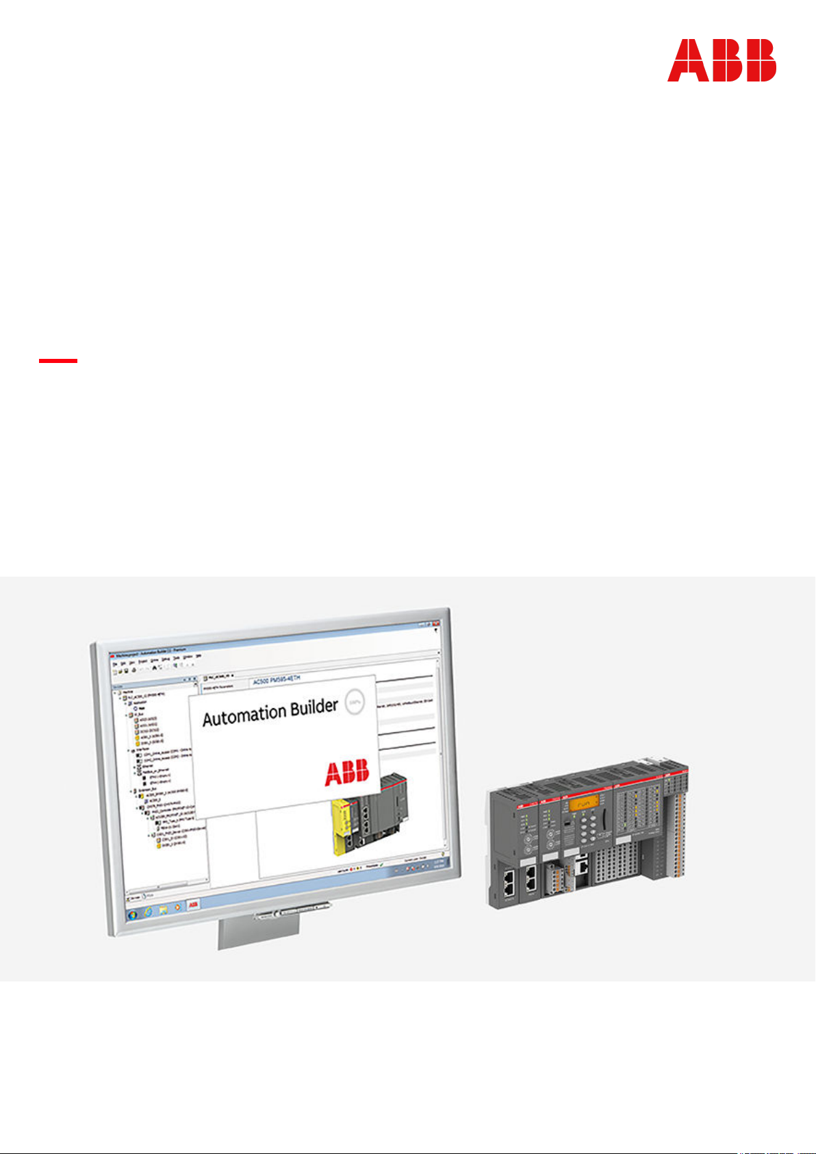
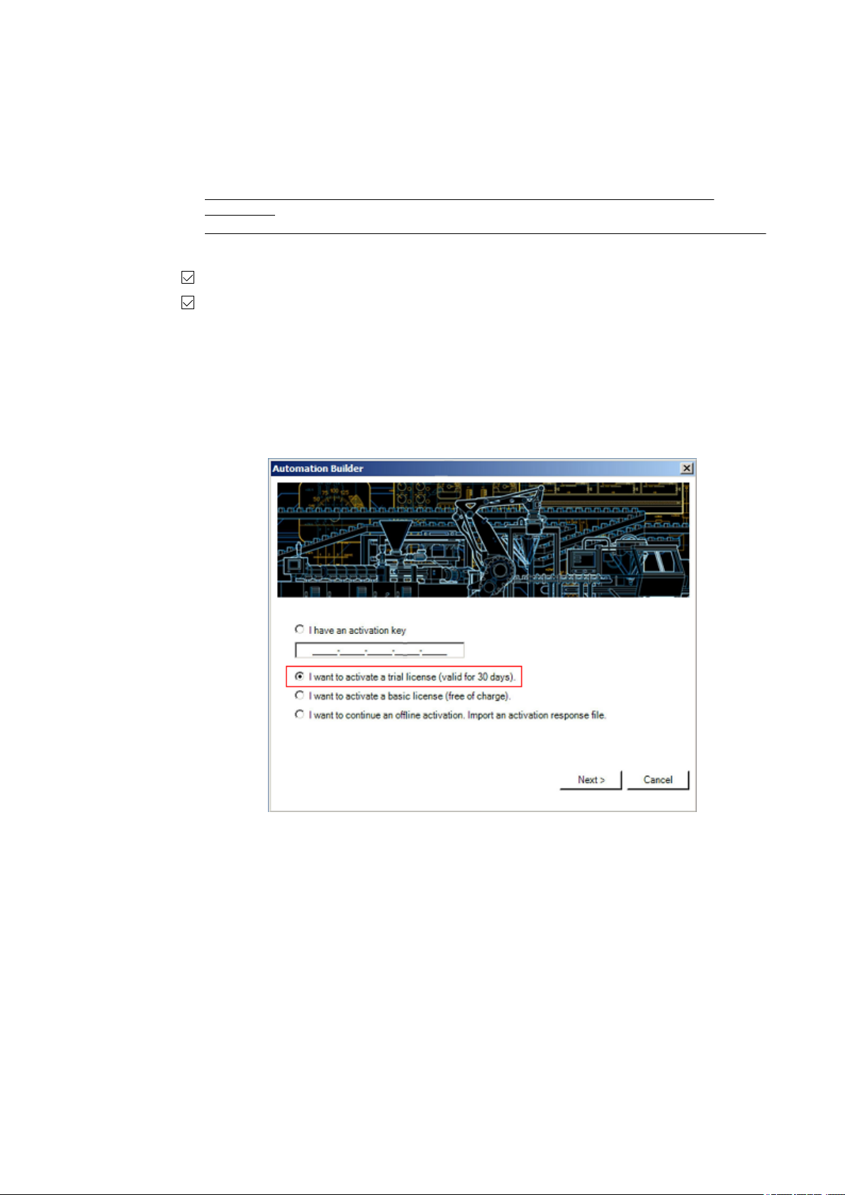
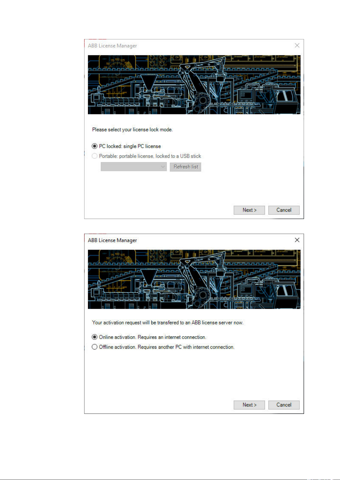
● installation of the engineering software
Ä
Chapter 1.3 “Engineering software Automation
Builder” on page 6
● hardware needed for example projects
Ä
Chapter 1.4 “Hardware AC500 V2” on page 10
● setting up a first, simple project for a stand-alone CPU with central I/O expansion, including
visualization and web visualization
Ä
Chapter 1.5 “Example project for central I/O expan-
sion” on page 13
● commissioning a project for remote I/O expansion with PROFINET
Ä
Chapter 1.6 “Example
project for remote I/O expansion with PROFINET” on page 52
1.2 Safety instructions
Relevant standards and regulations, accident prevention regulations and regulations on spe-
cial environmental conditions must be observed (e.g., hazardous areas due to explosive sub-
stances, heavy soiling or corrosive influences).
The devices must be handled and operated within the specified technical data and system data.
The devices contain no serviceable parts and must not be opened.
Removable covers must be closed during operation unless otherwise specified.
Any liability for the consequences of incorrect use or unauthorized repairs is rejected.
Both the AC500 control system and other components in the vicinity are operated with dan-
gerous touch voltages. Touching live components can lead to serious health implications or
even death.
To avoid such risks and the occurrence of property damage, persons involved in the installation,
commissioning and maintenance must have relevant knowledge about:
● Automation technology
● Handling of hazardous voltages
● Application of relevant standards and regulations, accident prevention regulations and reg-
ulations on special environmental conditions (e.g., hazardous areas due to explosive sub-
stances, heavy soiling or corrosive influences).
The AC500-S safety user manual must be read and understood before using the safety configu-
ration and programming tools of Automation Builder/PS501 Control Builder Plus. Only qualified
personnel are permitted to work with AC500-S safety PLCs.
The examples and diagrams in this manual are included solely for illustrative purposes.
Because of the many variants and requirements associated with any particular installation, ABB
cannot assume responsibility or liability for actual use based on the examples and diagrams.
The PLC was developed according to the relevant standards. Any module-specific measures
are described in the individual descriptions of the modules.
Qualified per-
sonnel
Functional
safety
General infor-
mation
Getting started with example projects
Safety instructions
2023/03/03 3ADR010649, 3, en_US 3

The product family AC500 control system is designed according to the EN
61131-2 and IEC 61131-2 standards. Any data that differs from IEC 61131-2,
is due to the higher requirements of Maritime Services. Other differences are
described in the technical data description of the devices.
NOTICE!
Avoidance of electrostatic charging
PLC devices and equipment are sensitive to electrostatic discharge, which can
cause internal damage and affect normal operation. Observe the following rules
when handling the system:
– Touch a grounded object to discharge potential static.
– Wear an approved grounding wrist strap.
– Do not touch connectors or pins on component boards.
– Do not touch circuit components inside the equipment.
– If available, use a static-safe workstation.
– When not in use, store the equipment in appropriate static-safe packaging.
NOTICE!
Use of suitable enclosure
The devices must be mounted in a control cabinet that ensures compliance with
the specified environmental conditions.
Cleaning instructions
Do not use cleaning agent for cleaning the device.
Use a damp cloth instead.
Connection plans and a user program must be created so that no dangerous situations can
occur during normal operation or failure.
The application must be tested to ensure that no dangerous situations can occur during opera-
tion.
Do not operate devices outside of the specified, technical data!
Trouble-free functioning cannot be ensured outside of the specified data.
NOTICE!
PLC damage due to missing grounding
– Make sure to ground the devices.
– The grounding (switch cabinet grounding) is supplied both by the mains
connection (or 24 V supply voltage) and via the DIN rail. The DIN rail
must be connected to ground before power is supplied to the device. The
grounding may be removed only if it is certain that no more power is being
supplied to the control system.
– In case of screw mounting, grounding must be ensured by the screws.
PLC-specific
safety notices
Getting started with example projects
Safety instructions
2023/03/033ADR010649, 3, en_US4

CAUTION!
Do not obstruct the ventilation for cooling!
The ventilation slots on the upper and lower sides of the devices must not be
covered.
CAUTION!
Run signal and power wiring separately!
Signal and supply lines (power cables) must be laid out so that no malfunctions
due to capacitive and inductive interference can occur (EMC).
WARNING!
Warning sign on the module!
This indicates that dangerous voltages may be present or that surfaces may
have dangerous temperatures.
WARNING!
Splaying of strands can cause hazards!
Avoid splayed strands when wiring terminals with stranded conductors.
– Ferrules can be used to prevent splaying.
WARNING!
Removal/Insertion under power
Removal or insertion under power is permissible only if all conditions for hot
swapping are fullfilled.
The devices are not designed for removal or insertion under power when the
conditions for hot swap do not apply. Because of unforeseeable consequences,
it is not allowed to plug in or unplug devices with the power being ON.
Make sure that all voltage sources (supply and process voltage) are switched
off before you
– connect or disconnect any signal or terminal block
– remove, mount or replace a module.
Disconnecting any powered devices while they are energized in a hazardous
location could result in an electric arc, which could create an ignition source
resulting in fire or explosion.
Prior to proceeding, make sure that power is been disconnected and that the
area has been thoroughly checked to ensure that flammable materials are not
present.
The devices must not be opened when in operation. The same applies to the
network interfaces.
Getting started with example projects
Safety instructions
2023/03/03 3ADR010649, 3, en_US 5
Table of contents
Other ABB Industrial Equipment manuals