ABB OHB Quick guide

OHB
Istruzioni per l'installazione e l'esercizio
Installation and service instructions


647026/001 - M5121 - 07-02-2002 - it-en - 1/28
Per la vostra sicurezza!
• Verificarecheilsitodiinstallazione(spazi,segregazioni
e ambiente) sia idoneo per l'apparechiatura elettrica.
• Verificare che tutte le operazioni di installazione, messa
inservizioemanutenzionesianoeffettuatedapersonale
con una adeguata conoscenza dell'apparecchiatura.
• Verificare che durante le fasi di installazione, esercizio
e manutenzione vengano rispettate le prescrizioni
normative e di legge, per l'esecuzione degli impianti in
accordo con le regole della buona tecnica e di sicurezza
sul lavoro.
• Osservare scrupolosamente le informazioni riportate
nel presente manuale di istruzione.
• Verificare che durante il servizio non vengano superate
le prestazioni nominali dell'apparecchio.
• Prestare particolare attenzione alle note indicate nel
manuale dal seguente simbolo:
• Verificare che il personale operante sull'apparecchiatu-
raabbiaadisposizioneilpresentemanualediistruzione
e le informazioni necessarie ad un corretto intervento.
!
Un comportamento responsabile
salvaguarda la vostra e l'altrui sicurezza!
Per qualsiasi esigenza contattare il
Servizio Assistenza ABB.
For your safety!
• Make sure that the installation site (spaces, divisions
and ambient) are suitable for the electrical apparatus.
• Check that all the installation, putting into service and
maintenance operations are carried out by qualified
personnel with in-depth knowledge of the apparatus.
• Make sure that the standard and legal prescriptions are
complied with during installation, putting into service
and maintenance, so that installations according to the
rules of good working practice and safety in the work
place are constructed.
• Strictly follow the information given in this instruction
manual.
• Checkthattheratedperformanceoftheapparatusisnot
exceeded during service.
• Payspecialattentiontothedangernotesindicatedinthe
manual by the following symbol:
• Check that the personnel operating the apparatus have
this instruction manual to hand as well as the necessary
information for correct intervention.
!
Responsible behaviour
safeguards your own and others’ safety!
For any requests, place contact the
ABB Assistance Service.

2/28 - 647026/001 - M5121 - 07-02-2002 - it-en
Premessa
Questa pubblicazione contiene le informazioni necessarie
per l'installazione e la messa in servizio degli interruttori di
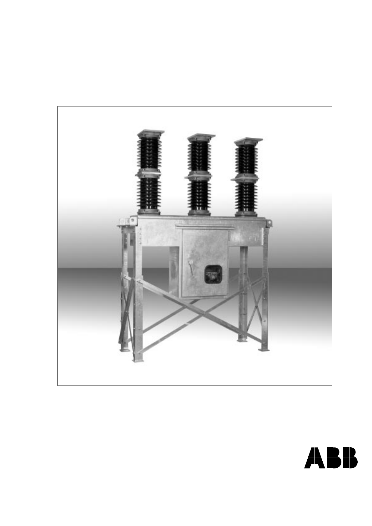
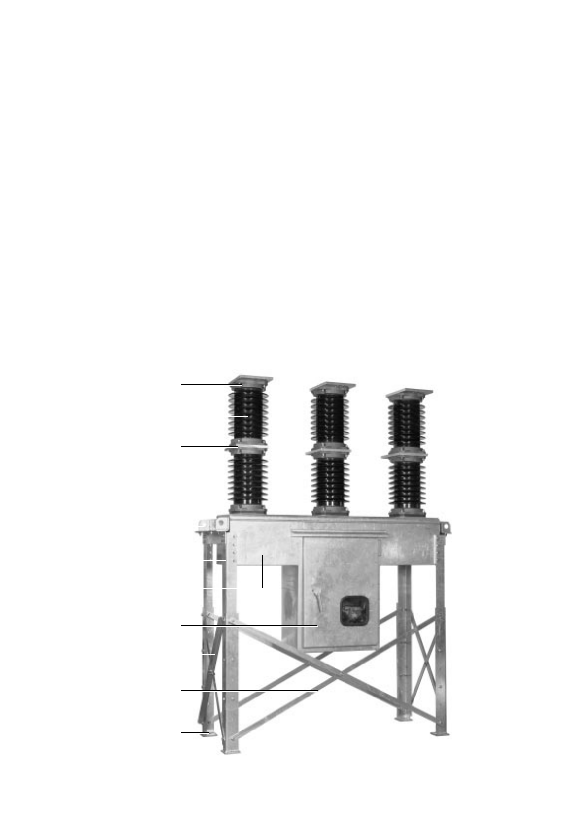
media tensione per esterno OHB.
Per il corretto impiego del prodotto se ne raccomanda una
attenta lettura.
Per il corretto montaggio di accessori e/o ricambi fare riferi-
mento alle apposite istruzioni.
Come tutti gli apparecchi di nostra costruzione, anche gli OHB
sono progettati per differenti configurazioni di impianto.
Questi apparecchi consentono tuttavia ulteriori variazioni tec-
nico-costruttive (su richiesta del cliente) per adeguamenti a
particolari esigenze impiantistiche. Per questo motivo le infor-
mazioni di seguito riportate possono talvolta mancare delle
istruzioni relative a configurazioni particolari.
È pertanto necessario fare sempre riferimento, oltre che a
questolibretto, anchealla documentazionetecnica piùaggior-
nata(schemacircuitale,schemitopografici,disegnidimontag-
gio e installazione, eventuali studi di coordinamento delle
protezioni, ecc.) specialmente in relazione alle eventuali va-
rianti richieste rispetto alle configurazioni normalizzate.
Tutte le operazioni inerenti l'installazione, la messa
in servizio, l'esercizio e la manutenzione devono
essere eseguite da personale che abbia una quali-
fica sufficiente e una conoscenza dettagliata del-
l'apparecchiatura.
Per gli interventi di manutenzione utilizzare solo parti di ricam-
biooriginali. Perulteriori informazionivedere ancheil catalogo
tecnico dell'interruttore e il catalogo ricambi.
Programma per la tutela dell’ambiente
GliinterruttoriOHBsonorealizzatinelrispettodelleNormeISO
14000 (Linee guida per la gestione ambientale).
Iprocessi produttivisono attuatinel rispetto delleNorme perla
tutela dell’ambiente in termini di riduzione sia dei consumi
energetici e di materie prime che di produzione degli scarti.
Tutto ciò grazie al sistema di gestione ambientale dello stabi-
limento di produzione delle apparecchiature di media tensio-
ne.
La valutazione dell’impatto ambientale nel ciclo di vita del
prodotto(LCA-LifeCycleAssessment),ottenutaminimizzando
il consumo di energia e di materie prime complessive del
prodotto, si è concretizzata nella fase di progettazione me-
diantelasceltamiratadeimateriali,deiprocessiedegliimballi.
Per la fabbricazione degli interruttori sono in atto tecniche di
produzione che predispongono i prodotti per un facile
smontaggio e una facile separazione dei componenti. Ciò al
fine di consentire la massima riciclabilità alla fine del ciclo di
vita utile dell’apparecchio.
Introduction
This publication contains the information necessary for instal-
lation and putting into service of OHB outdoor medium voltage
circuit-breakers.
For correct usage of the product, please read this manual
carefully.
For correct mounting of accessories and/or spare parts please
refer to the relevant instructions.
Like all the apparatus manufactured by us, the OHB circuit-
breakers are designed for different installation configurations.
They do, however, allow further technical-constructional vari-
ations (at the customer’s request) to suit special installation
requirements.
For this reason, the information given below does not always
cover special configurations.
Apartfromthisbooklet,itisthereforealwaysnecessarytorefer
to the latest technical documentation available (circuit dia-
gram, wiring diagrams, assembly and installation drawings,
any studies of protection co-ordination, etc.), especially with
regard to any variations from standardized configurations
requested.
Alltheoperationsregardinginstallation,puttinginto
service,operationandmaintenancemustbecarried
out by suitably qualified personnel with in-depth
knowledge of the apparatus.
Only use original spare parts for maintenance operations.
For further information, also see the technical catalogue of the
circuit-breaker and the spare parts catalogue.
Environmental protection programme
The OHB circuit-breakers are manufactured in accordance
with the ISO 14000 Standards (Guidelines for environmental
management).
The production processes are carried out in compliance with
the Standards for environmental protection in terms of reduc-
tion in energy consumption as well as in raw materials and
production of waste materials. All this is thanks to the medium
voltage apparatus manufacturing facility environmental man-
agement system.
Assessmentof the environmentalimpact ofthelife cycleof the
product (LCA - Life Cycle Assessment), obtained by minimis-
ing energy consumption and overall raw materials of the
product, became a concrete matter during the design stage by
means of targeted selection of the materials, processes and
packing.
Production techniques which prepare the products for simple
dismantling and separation of the components are used dur-
ing manufacture of the circuit-breakers. This is to allow maxi-
mum recycling at the end of the useful life cycle of the appara-
tus.
! !

647026/001 - M5121 - 07-02-2002 - it-en - 3/28
Indice
1. Imballaggio e trasporto 4
2. Controllo al ricevimento 4
3. Magazzinaggio 5
4. Sollevamento 6
5. Descrizione 7
5.1. Norme di riferimento 7
6. Istruzioni per la manovra dell'interruttore 8
6.1. Organi di manovra e segnalazione 8
6.2. Indicazioni di sicurezza 9
6.3. Manovra di chiusura
e di apertura dell'interruttore 9
7. Installazione 10
7.1. Generalità 10
7.2. Condizioni normali di installazione 10
7.3. Operazioni preliminari 10
7.4. Predisposizione del piano di fissaggio
e fissaggio dell'interruttore 10
7.5. Montaggio della struttura telescopica 14
7.6. Montaggio mensola trasformatori
di corrente (se prevista) 17
7.7. Adattamento dell'altezza (per interruttori
con supporti telescopici) 18
7.8. Connessioni del circuito di potenza 19
7.9. Messa a terra 20
7.10. Collegamento dei circuiti ausiliari 20
7.11. Dimensioni di ingombro 21
8. Messa in servizio 23
8.1. Procedure generali 23
9. Controlli periodici 25
9.1. Generalità 25
9.2. Programma di controllo 25
10. Operazioni di manutenzione 26
11. Indicazioni per la manipolazione
degli apparecchi con SF6 27
12. Parti di ricambio e accessori 28
12.1. Elenco ricambi 28
Index
1. Packing and transport 4
2. Checking on receipt 4
3. Storage 5
4. Lifting 6
5. Description 7
5.1. Reference Standards 7
6. Instructions for circuit-breaker operation 8
6.1. Operating and signalling parts 8
6.2. Safety indications 9
6.3. Circuit-breaker closing and
opening operations 9
7. Installation 10
7.1. General 10
7.2. Normal installation conditions 10
7.3. Preliminary operations 10
7.4. Preparing the fixing surface and
circuit-breaker fixing 10
7.5. Assembly for the telescopic structure
14
7.6.
Assembly of the current transformer
shelf (on request) 17
7.7. Adaptation of the height (for circuit-breakers
with telescopic supports) 18
7.8. Power circuit connections 19
7.9. Earthing 20
7.10. Auxiliary circuit connection 20
7.11. Overall dimensions 21
8. Putting into service 23
8.1. General procedures 23
9. Periodical checks 25
9.1. General 25
9.2. Checking programme 25
10. Maintenance operations 26
11. Indications for handling
apparatus with SF6 27
12. Spare parts and accessories 28
12.1. List of spare parts 28

4/28 - 647026/001 - M5121 - 07-02-2002 - it-en
1.Imballaggio e trasporto
L’interruttore viene spedito in apposito imballo in posizione
aperto, con molle scariche e con pressione assoluta del polo
corrispondente al valore di esercizio.
Ciascun apparecchio è protetto da involucro in plastica in
modo da evitare infiltrazioni d'acqua durante le fasi di carico e
scarico, e per preservarlo dalla polvere durante l'immagazzi-
namento.
I trasformatori di corrente, se previsti, la relativa mensola e gli
eventuali dispositivi di fissaggio, forniti a richiesta, vengono
imballati e spediti a parte.
Idispositividifissaggiodell'interruttore, forniti arichiesta,sono
inseriti nello stesso imballo di spedizione.
2. Controllo al ricevimento
Prima di eseguire qualsiasi operazione verificare
sempre che le molle del comando siano scariche e
l'apparecchioin posizione di aperto.
Al ricevimento controllare lo stato dell’apparecchio, l’integrità
dell’imballaggio e la corrispondenza dei dati di targa (vedi fig.
1) con quelli specificati nella conferma d’ordine e nella bolla di
accompagnamento trasporto.
Accertare inoltre che nella fornitura siano compresi tutti i
materiali descritti nella bolla di spedizione.
Se al disimballo venisse riscontrato qualche danno o irregola-
rità nella fornitura, avvertire ABB (direttamente, attraverso il
rappresentante o il fornitore) il più presto possibile e in ogni
caso entro cinque giorni dal ricevimento.
L’apparecchio viene fornito con i soli accessori specificati in
sede d’ordine e convalidati nella conferma d’ordine inviata da
ABB.
Idocumenti diaccompagnamento inseritinell’imballo dispedi-
zione sono:
– Manuale di istruzione (il presente documento)
– Attestazione di collaudo
– Cartellino di identificazione
– Copia fiscale dell’avviso di spedizione
– Schema elettrico.
Altri documenti che precedono l’invio dell’apparecchio sono:
– Conferma d’ordine
– Originale dell’avviso di spedizione.
– Eventuali disegni o documenti riferiti a configurazioni/condi-
zioni particolari.
1.Packing and transport
The circuit-breaker is shipped in special packing in the open
position with the springs discharged and with absolute pole
pressure corresponding with the service value.
Eachpieceofapparatusisprotectedbyaplasticfilmtoprevent
any infiltration of water during the loading and unloading
stages and to keep the dust off during storage.
If provided, the current transformers, the relative shelf and any
fixing devices, supplied on request, are packed and shipped
separately.
The circuit-breaker fixing devices - supplied on request - are
put into the same shipping packing.
2.Checking on receipt
Before carrying out any operation, always make
sure that the operating mechanism dprings are dis-
charged and that the apparatus is in the open posi-
tion.
On receipt, check the state of the apparatus, that the packing
is undamaged and that the nameplate data corresponds (see
fig. 1) with that specified in the order acknowledgement and in
the delivery note.
Also make sure that all the materials described in the shipping
note are included in the supply.
Ifanydamage orirregularityisdiscoveredonunpacking,notify
ABB (directly or through the agent or supplier) as soon as
possible and in any case within five days of receipt.
The apparatus is only supplied with the accessories specified
at the time of order and confirmed in the order acknowledge-
ment sent by ABB.
The following accompanying documents are inserted in the
shipping packing:
– Instruction manual (this document)
– Test certificate
– Identification tag
– Fiscal copy of shipping note
– Electrical diagram
These other documents are sent prior to shipment:
– Order acknowledgement
– Original copy of shipping note
– Any drawings or documents regarding special configura-
tions/conditions.
! !

647026/001 - M5121 - 07-02-2002 - it-en - 5/28
CIRCUIT-BREAKER IEC 62271-100
OHB ... CEI 17-1
No. ... MASS ... kg
RATED VOLTAGE ... kV
IMPULSE WITHSTAND VOLTAGE ... kV
RATED FREQUENCY 50/60 Hz
RATED NORMAL CURRENT ... A
SHORT-TIME CURRENT (1 s) ... kA
CLOSING/OPENING TIME ... ms
ABSOLUTE SF6 PRESSURE AT 20 °C ... kPa
BREAKING CAPACITY ... kA
MAKING CAPACITY ... kA
AT VOLTAGE OF ... kV
OPERATION SEQUENCE ...
OPERATING MECHANISM IEC 62271-100
ESH CEI 17-1
No. ...
YC ... V —
YU ... V —
YO1 ... V —
H ... V —
M ... V —
Legenda
A Targa caratteristiche dell’interruttore
B Targa caratteristiche del comando
1 Tipo di apparecchio
2 Simboli di rispondenza alle Norme
3 Numero di matricola
4 Caratteristiche dell’interruttore
5 Caratteristiche degli ausiliari di comando
Caption
A Circuit-breaker nameplate
B Operating mechanism nameplate
1 Type of apparatus
2 Symbols and compliance with Standards
3 Serial number
4 Circuit-breaker characteristics
5 Characteristics of the operating auxiliaries
1
A
B
3
4
5
2
INTERRUTTORE IEC 62271-100
OHB ... CEI 17-1
NR. ... MASSA ... kg
TENSIONE NOMINALE ... kV
TENSIONE DI TENUTA AD IMPULSO ATM. ... kV
FREQUENZA NOMINALE 50/60 Hz
CORRENTE TERMICA NOMINALE ... A
CORRENTE DI BREVE DURATA (1 s) ... kA
DURATA DI CHIUSURA / APERTURA ... ms
PRESSIONE ASSOLUTA SF6 20 °C ... kPa
POTERE DI INTERRUZIONE ... kA
POTERE DI STABILIMENTO ... kA
ALLA TENSIONE DI ... kV
SEQUENZA OPERAZIONI ...
COMANDO IEC 62271-100
ESH CEI 17-1
NR. ...
YC ... V —
YU ... V —
YO1 ... V —
H ... V —
M ... V —
1
A
B
3
4
5
2
Targa caratteristiche
Fig. 1
Nameplate
3.Storage
When a period of storage is foreseen, (on request) our work-
shops can provide suitable packing for the specified storage
conditions.
On receipt the apparatus must be carefully unpacked and
checked as described in Checking on receipt (chap. 2).
If immediate installation is not possible, the packing must be
replaced, using the original material supplied.
Inserthygroscopic substancesinside thepacking, withat least
one standard bag per piece of apparatus.
Should the original packing not be available and immediate
installation is not possible, store in covered, well-ventilated,
dry, dust-free, non-corrosive ambients, away from any flam-
mable materials and at a temperature between –5 °C and +45
°C.
In any case, avoid any accidental impacts or positioning which
stresses the structure of the apparatus.
3. Magazzinaggio
Nel caso sia previsto un periodo di magazzinaggio, le nostre
officine (su richiesta) provvedono ad un imballaggio adeguato
alle condizioni di immagazzinaggio specificato.
Al ricevimento l'apparecchio deve essere accuratamente di-
simballato e controllato come descritto al Controllo al ricevi-
mento (cap. 2).
Qualora non sia possibile l'immediata installazione, deve es-
sere ripristinato l'imballo utilizzando il materiale originale.
Inserirenell'imballoappositesostanzeigroscopichenellaquan-
tità di almeno un sacchetto standard per apparecchio.
Qualora non sia più disponibile l'imballo originale e non sia
possibilel'immediata installazioneprovvedere almagazzinag-
gioin ambiente coperto, ben ventilato, con atmosferaasciutta,
non polverosa, non corrosiva, lontano da materiali facilmente
infiammabili e con temperatura compresa tra –5 °C e +45 °C.
In ogni caso evitare urti accidentali o sistemazioni che solleci-
tino la struttura dell'apparecchio.
Designed and manufactured by ABB T & D S.p.A. Unità operativa Sace T.M.S. Designed and manufactured by ABB T & D S.p.A. Unità operativa Sace T.M.S.

6/28 - 647026/001 - M5121 - 07-02-2002 - it-en
4. Sollevamento
Lemanovredisollevamentodevonoessereeseguitemediante
parancoocarroponte.
– Mediante gli appositi moschettoni agganciare le funi alla
struttura dell'interruttore.
– Agganciare agli appositi punti di ancoraggio previsti nella
strutturae sollevare.
Ipesicomplessividelleapparecchiaturesonoriportatidiseguito:
– interruttoresutelaio:750kg
– interruttore su carrello: 700 kg
– mensola per trasformatori di corrente: 50 kg.
Fig. 2
4. Lifting
Theliftingoperationsmustbecarriedoutusingahoistorbridge
crane.
– Bymeansofthespecialspringcatches,hooktheropestothe
circuit-breaker structure
– Hook to the special anchoring points provided in the struc-
ture and lift.
The overall weights of the apparatus are indicated below:
– Circuit-breaker on frame: 750 kg
– Circuit-breaker on truck: 700 kg
– shelf for current transformers: 50 kg.

647026/001 - M5121 - 07-02-2002 - it-en - 7/28
1
2
3
4
5
6
7
8
9
10
5. Descrizione
GliinterruttoridimediatensioneperesternoOHB,impieganogas
esafluoruro di zolfo per l’estinzione dell’arco elettrico e come
mezzoisolante.
Il comando meccanico, tipo ESH, è ad accumulo di energia a
sgancio libero e consente manovre di apertura e chiusura
indipendenti dall’operatore.
Il comando, il cinematismo di azionamento dei contatti mobili,
tutti i circuiti di controllo, comando e la resistenza anticonden-
sa, sono posti all’interno del cofano metallico a tenuta stagna
che funge anche da supporto dei poli.
La suddetta struttura può essere sorretta da un carrello (ver-
sione su carrello) oppure da un telaio (versione su telaio)
realizzato con profilati metallici telescopici che permettono di
adattare l’altezza dell’interruttore da 2900 mm a 3700 mm.
IlcofanometallicohaungradodiprotezioneIP54(sepredispo-
sto con filtri, a richiesta, sui fori di aerazione sul fondo del
cassone)edèdotatodiunaportaatenutaconoblò.Lamaniglia
della porta è predisposta per l’applicazione di tre lucchetti con
ganciodi8mmdidiametro.
5.1. Norme di riferimento
Gli interruttori OHB sono conformi alle norme IEC 62271-100,
CEI 17-1 fascicolo 1375, CENELEC HD 348 S3 e a quelle dei
principali paesi industriali.
Fig. 3
5. Description
The OHB medium voltage circuit-breakers for outdoor instal-
lation use sulphur hexafluoride to extinguish the electric arc
and as the insulating means.
The mechanical operating mechanism is of the ESH type with
stored energy and free release and allows opening and
closing operations independent of the operator.
The operating mechanism, the moving contact activating kin-
ematics, all the control and operating circuits and the anti-
condensation heater are located inside the tight metal case
which also acts as the support for the poles.
The above-mentioned structure can be supported by a truck
(version on truck) or by a frame (version on frame) made of
telescopic metal sections which allow the height of the circuit-
breaker to be adapted from 2900 mm to 3700 mm.
Themetal casehas IP54 degreeof protection(if providedwith
filters- optional-over theventilation holesonthe bottomof the
box) and is fitted with a tight door with inspection window. The
door handle is preset for application of three padlocks with 8
mm diameter hook.
5.1. Reference Standards
OHB circuit-breakers comply with the IEC 62271-100, CEI 17-
1 file 1375, CENELEC HD 348 S3 Standards as well as those
of major industrialised countries.
Legenda
1 Terminali superiori
2 Isolatori di porcel-
lana
3 Terminali inferiori
4 Ganci per il solle-
vamento
5 Profilati telescopici
6 Cassonetto poli e
comando
7 Porta con oblò
8 Traverse laterali
9 Traverse frontali e
posteriori
10 Staffa di fissaggio
Caption
1 Upper terminals
2 Porcelain insula-
tors
3 Lower terminals
4 Hooks for lifting
5 Telescopic sec-
tions
6 Pole and operat-
ing mechanism
box
7 Door with inspec-
tion window
8 Side crosspieces
9 Front and rear
crosspieces
10 Fixing bracket

8/28 - 647026/001 - M5121 - 07-02-2002 - it-en
12
23
22
21
20
19
18
17
16
15
14 1312 11
10 8
4
5
6
7
9
3
24 25
6.Istruzioni per la manovra
dell'interruttore
6.1. Organi di manovra e segnalazione
Fig. 4
Legenda
1 Morsettiera dei circuiti di comando e segnalazione (XA)
2 Morsettiera amperometrica (XD) (a richiesta)
3 Ritardatore elettronico dello sganciatore di minima tensione (a
richiesta)
4 Termostato
5 Lampade di segnalazione (a richiesta)
6 Segnalatore molle cariche/scariche
7 Contatto di finecorsa del motore carica molle
8 Resistenza anticondensa
9 Innesto manovella per la carica delle molle di chiusura
10 Segnalatore interruttore aperto
11 Segnalatore interruttore chiuso
12 Pulsante di chiusura
13 Pulsante di apertura
14 Contatti ausiliari dell'interruttore
15 Presa di alimentazione di servizio (a richiesta)
16 Pulsante di chiusura e apertura elettrica locale (a richiesta)
17 Commutatore locale/distanza (a richiesta)
18 Sganciatori di apertura e di chiusura (e di minima tensione se
richiesta)
19 Morsettiera dei circuiti di comando e segnalazione (XA)
20 Contatti di posizione della porta
21 Morsettiera dei contatti ausiliari dell'interruttore rinviati meccani-
camente (contatti ausiliari supplementari a richiesta)
22 Interruttori di protezione dei circuiti ausiliari (a richiesta)
23 Relè ausiliari di apertura e di chiusura (forniti di serie solo se la
tensione di alimentazione è inferiore a 110 V c.c.)
24 Maniglia della porta (predisposta per l'applicazione di tre luc-
chetti con gancio di 8 mm di diametro, a richiesta)
25 Oblò
6.Instructions for circuit-breaker
operation
6.1. Operating and signalling parts
Caption
1 Terminal box of the operating and signalling circuits (XA)
2 Current terminal box (XD) (on request)
3 Undervoltage release electronic time-delay device (on re-
quest)
4 Thermostat
5 Signalling lamps (on request)
6 Springs charged/discharged signalling device
7 Spring charging motor limit switch contact
8 Anti-condensation heater
9 Coupling for closing spring charging handle
10 Signalling device for circuit-breaker open
11 Signalling device for circuit-breaker closed
12 Closing pushbutton
13 Opening pushbutton
14 Circuit-breaker auxiliary contacts
15 Service power supply socket (on request)
16 Local closing and opening pushbutton (on request)
17 Local/remote change-over switch (on request)
18 Shunt opening and closing releases (and undervoltage release
if requested)
19 Operating and signalling circuit terminals box (XA)
20 Door position contacts
21 Terminal box of the circuit-breaker auxiliary contacts transmit-
ted mechanically (additional auxiliary contacts on request)
22 Auxiliary circuit protection circuit-breaker (on request)
23 Auxiliary opening and closing relays (supplied as standard only
if the power supply voltage is less than 110 V d.c.)
24 Door handle (preset for application of three padlocks with 8 mm
diameter hook, on request)
25 Inspection window

647026/001 - M5121 - 07-02-2002 - it-en - 9/28
6.2. Indicazioni di sicurezza
Qualora vengano effettuate manovre meccaniche
sull'interruttore all'interno dell'area di installazione
o con reti di protezioni rimosse, prestare la massi-
ma attenzione alle parti in movimento ed alla linea
di media tensione.
Se le manovre risultassero impedite non forzare gli
interblocchi meccanici e verificare la correttezza
della sequenza delle manovre.
6.3. Manovre di chiusura
e di apertura dell’interruttore
La manovra dell’interruttore può essere manuale o elettrica.
a) Manovra manuale di carica molle
Per caricare manualmente le molle di chiusura è necessario
inserire a fondo la leva di carica nella sede (9) e ruotare in
senso orario fino alla comparsa del segnalatore (6) di colore
giallo. Lo sforzo normalmente applicabile alla leva di carica in
dotazione è 130 N. In ogni caso lo sforzo massimo applicato
non deve superare 170 N.
b) Manovra elettrica di carica molle
A richiesta l’interruttore può essere dotato dei seguenti acces-
sori per la manovra elettrica:
– motoriduttore per la carica automatica delle molle
– sganciatore di chiusura
– sganciatore di apertura.
Il motoriduttore ricarica automaticamente le molle dopo ogni
operazione di chiusura fino alla comparsa del segnalatore
giallo (6). In caso di mancanza di tensione durante la carica, il
motoriduttore si ferma e riprende automaticamente la ricarica
delle molle al ritorno della tensione. È sempre comunque
possibile completare l’operazione di ricarica manualmente.
c) Chiusura dell’interruttore
L’operazione può essere eseguita solo a molle di chiusura
completamente cariche.
Per la chiusura manuale premere il pulsante (12).
Inpresenzadisganciatoredichiusural’operazionepuòessere
eseguita anche a distanza mediante apposito circuito di con-
trollo. L’avvenuta chiusura è indicata dal segnalatore (11).
d) Apertura dell’interruttore
Per l’apertura manuale premere il pulsante (13).
Inpresenzadisganciatorediapertural’operazionepuò essere
eseguita anche a distanza mediante apposito circuito di con-
trollo. L’avvenuta apertura è indicata dal segnalatore (10).
!
6.2. Safety indications
Shouldmechanicaloperationsbecarriedoutonthe
circuit-breakerinsidetheinstallationareaorwiththe
protection nets removed, pay great attention to the
moving parts and to the medium voltage line.
Shouldtheoperationsbeprevented,donotforcethe
mechanical interlocks and check that the operation
sequence is correct.
6.3. Circuit-breaker closing
and opening operations
Circuit-breaker operation can be manual or electrical.
a) Manual operation for spring charging
To manually charge the closing springs, it is necessary to
fully insert the charging lever into the seat (9) and turn it
clockwise until the yellow indicator (6) appears. The force
which can normally be applied to the charging lever fitted is
130 N. In any case, the maximum force applied must not
exceed 170 N.
b) Electrical operation for spring charging
On request the circuit-breaker can be fitted with the following
accessories for electrical operation:
– geared motor for automatic charging of the closing springs
– shunt closing release
– shunt opening release.
The geared motor automatically recharges the springs after
each closing operation until the yellow indicator (6) appears.
Should there be no voltage during charging, the geared motor
stops and then starts recharging the springs automatically
when the voltage is on again. It is, however, always possible
to complete the charging operation manually.
c) Circuit-breaker closing
This operation can only be carried out with the closing springs
completely charged.
For manual closing, press the pushbutton (12).
When there is a shunt closing release, the operation can also
becarried outwithremote controlbymeans ofa controlcircuit.
The indicator (11) shows that closing has been accomplished.
d) Circuit-breaker opening
For manual opening, press the pushbutton (13).
When there is a shunt opening release, the operation can also
becarried outwithremote controlbymeans ofa controlcircuit.
The indicator (10) shows that opening has been accom-
plished.
!

10/28 - 647026/001 - M5121 - 07-02-2002 - it-en
> 15 kN
> 20 kN
!!
7. Installazione
7.1. Generalità
Una corretta installazione è di primaria importanza.
Le istruzioni del costruttore devono essere attenta-
mente studiate e seguite. È buona norma l'utilizzo
dei guanti per la manipolazione dei pezzi durante
l'installazione.
7.2. Condizioni normali di installazione
Temperatura massima dell'aria ambiente + 40 °C
Temperatura minima dell'aria ambiente – 25 °C
Umidità relativa % < 95
Altitudine < 1000 m
Peraltre caratteristichedell'ambiente diinstallazioneattenersi
a quanto indicato dalle norme di prodotto. Per particolari
esigenze di installazione contattateci.
Lezone interessatedal passaggiodi conduttoridi potenzao di
conduttori dei circuiti ausiliari devono essere protette contro
l'accesso di eventuali animali che potrebbero causare danni o
disservizi.
7.3. Operazioni preliminari
– Pulire le parti isolanti con strofinacci puliti e asciutti.
– Verificare che i terminali superiori e inferiori siano puliti ed
esenti da qualsiasi deformazione provocata da urti ricevuti
durante il trasporto o durante la permanenza a magazzino.
– Verificare che all'interno del cassone comando e della base
poli non siano presenti corpi estranei.
7.4. Predisposizione del piano di fissaggio e
fissaggio dell'interruttore
– Ilpianodifissaggiodell'interruttore deve essererealizzatoin
cemento armato e deve essere liscio e ben livellato. La
tolleranza di planarità massima ammessa è 2 x 1000.
– Ilfissaggiodell'interruttorepuòessereeffettuatodirettamen-
te a pavimento mediante quattro ancoranti ad espansione
(nonforniti)oppurecontirafondi(nonforniti).
– In caso di fissaggio con tasselli ad espansione possono
essere utilizzati ancoranti tipo HILTIHSA M 20x170. In ogni
caso gli ancoranti ad espansione devono essere di tipo ade-
guato affinché resistano ad una forza verticale di estrazione
³ 15 kN e ad una forza orizzontale di trazione ³ 20 kN.
– In caso di fissaggio con tirafondi, questi possono essere
realizzatiseguendoleindicazionidelparagrafo7.4.2.
– Prepararelefondazionicomeindicatoaiparagrafisuccessivi.
7.Installation
7.1. General
Correct installation is of prime importance. The in-
structions given by the manufacturer must be care-
fully studied and followed. It is good practice to use
gloves to handle the pieces during installation.
7.2. Normal installation conditions
Maximum ambient air temperature + 40 °C
Minimum ambient air temperature – 25 °C
Relative humidity % < 95
Altitude < 1000 m
For other installation conditions, please follow what is indi-
cated in the product Standards. For special installation re-
quirements please contact us.
The areas affected by the passage of power conductors or
auxiliary circuit conductors must be protected against the
possible access of animals which could cause damage or
anomalous service.
7.3. Preliminary operations
– Clean the insulating parts with clean dry rags.
– Check that the upper and lower terminals are clean and free
of any deformation caused by shocks received during
transport or storage.
– Check that there are no foreign bodies inside the operating
mechanism box and the pole base.
7.4. Preparing the fixing surface and circuit-
breaker fixing
– Thecircuit-breakerfixingsurfacemustbemadeofreinforced
concrete and must be smoothed and well levelled. The
maximum planarity tolerance allowed is 2 x 1000.
– Thecircuit-breakercanbefixeddirectlytothefloorbymeans
of four expansion anchoring bolts (not supplied) or with log
bolts (not supplied).
– In the case of fixing with expansion bolts, the HILTY HSA M
20x170 type can be used. In any case, the expansion
anchoring bolts must be of a suitable type to resist a vertical
extraction force of
³
15 kN and a horizontal traction force of
³
20 kN.
– In the case of fixing with log bolts, these must be made
following the indications given in paragraph 7.4.2.
– Prepare the foundations as indicated in the paragraphs
below.
Fig. 5

647026/001 - M5121 - 07-02-2002 - it-en - 11/28
Caption
1 Length of the steel reinforcement
2 Width of the steel reinforcement
3 Holes with 26 mm diam. for expansion bolts
4 Detail of the anchoring plate
5 Lean concrete
6 Surface and volume of the formwork
7.4.1. Preparazionedelbasamento perfissaggiocon
tasselliadespansione
Attenzione! Tuttele dimensionisonoin cm.
Fig.5a
Legenda
1 Lunghezza dell'armatura
2 Larghezza dell'armatura
3 Fori diametro 26 mm per tasselli ad espansione
4 Particolare della piastra di ancoraggio
5 Magrone di calcestruzzo
6 Superfice e volume del cassero
N.B.Perlasagomadell'armaturaelatabella
dei materiali vedere paragrafo 7.4.3.
N.B. Forthe shape ofthe steelreinforcement
and the table of materials, see paragraph
7.4.3.
7.4.1. Preparation of the base for fixing with expansion
anchoringbolts
Caution! All the dimensions are in cm.

12/28 - 647026/001 - M5121 - 07-02-2002 - it-en
7.4.2. Preparazione del basamento per fissaggio con
tirafondi
Attenzione! Tuttele dimensionisonoin cm.
Caption
1 Length of the steel reinforcement
2 Width of the steel reinforcement
3 Holes with 26 mm diam. for log bolts
4 Detail of the anchoring plate
5 Lean concrete
6 Surface and volume of the formwork
7 Log bolt
Fig. 5b
Legenda
1 Lunghezza dell'armatura
2 Larghezza dell'armatura
3 Fori diametro 26 mm per tirafondi
4 Particolare della piastra di ancoraggio
5 Magrone di calcestruzzo
6 Superfice e volume del cassero
7 Tirafondo
N.B. Per la sagoma
dell'armatura e la ta-
bella dei materiali ve-
dereparagrafo7.4.3.
N.B. For the shape of
the steel reinforce-
ment and the table of
materials, see para-
graph 7.4.3.
7.4.2. Preparation of the base for fixing with log bolts
Caution! All the dimensions are in cm.

647026/001 - M5121 - 07-02-2002 - it-en - 13/28
7.4.3. Caratteristichedei materiali, del terrenoedell'ar-
matura
Caratteristichedeimateriali
Calcestruzzo:
RcK 300.
Magronedi calcestruzzo:
100kg dicementoper m3di prodottoconfezionato.
Armature per calcestruzzo:
FeB44k.
Bullonigrezziperancoraggi(fissaggiocontirafondi):
Diametro nominale 16 mm (nucleo 13,4 mm) con
tensioneammisibile1220...1580kg.
Tasselli(fissaggio contasselli adespansione):
Tipo HILTY HSA M20 x 170.
Caratteristichedelterreno
Sollecitazioneammissibileminima:
0,5 kg / cm2.
Caratteristichedell'armatura
Posizione Quantità Diametro Lunghezzaelemento Sagoma Lunghezzatotale Unità
Item Quantity Diameter Length of the element Shape Totallength Unit
N. mm m m kg
1 16 10 3 48 29,62
2 16 12 2,3 36,8 32,68
3 4 20 0,37 1,48 3,66
Peso totale: 65,96 kg Total weight: 65,96 kg
230
R=6; a=90°
17 121
12
7.4.3. Characteristics of the materials, ground and steel
reinforcement
Characteristics of the materials
Concrete: RcK 300.
Lean concrete:
100 kg of cement per m
3
of made-up product.
Concrete steel reinforcements:
FeB44k.
Raw bolts for anchors (fixing with log bolts):
Nominal diameter: 16 mm (core 13.4 mm) with
admissible tension: 1220 …1580 kg.
Expansion bolts (fixing with expansion anchoring bolts):
HILTY HSA M 20x170 type.
Characteristics of the ground
Minimum admissible stress:
0,5 kg / cm
2.
Characteristics of the steel reinforcement

14/28 - 647026/001 - M5121 - 07-02-2002 - it-en
Fig. 6
!!
7.5. Assembly of the telescopic structure
•
checkthattheliftingequipmentissuitableforlifting
a load of more than 900 Kg;
•
thecircuit-breakerpolescontainSF6atapressure
of 380 Kpa (nominal service pressure).
•
two fixed spanners with CH19 are needed to as-
semble the telescopic structure.
Remove the cover and only the side walls of the packing crate.
For safety reasons, do not remove the front walls until the
structure has been hooked up to the lifting system. Open the
polyethylene bag containing the circuit-breaker (consisting of
the operating mechanism T-shaped enclosure, the poles and
the shelves with lifting hooks).
Hook up the four ropes to the special hooks provided on the
enclosure shelves and make the four ropes taut (see fig. 6). It
is only now possible to remove the front walls as well.
Inside the operating mechanism enclosure there are two packs
containing the following:
– no. 8 TE STAINLESS STEEL M12x20 Screws with STAIN-
LESS STEEL Spring Washers
– no. 44 TE STAINLESS STEEL M12x35 Screws with STAIN-
LESS STEEL M12 Self-locking Nuts
Remove the components of the telescopic structure from the
crate loading platform:
– no. 4 Top legs;
– no. 4 Bottom legs with plates for fixing to the ground;
– no. 2 L-shaped Crosspieces (front and rear)
– no. 2 Flat crosspieces (front and rear)
– no. 2 L-shaped Crosspieces (side)
– no. 2 Flat crosspieces (side)
Lift the circuit-breaker to a height suitable for positioning the
top legs.
Remove the loading platform of the packing crate.
7.5. Montaggio della struttura telescopica
•verificare che le attrezzature di sollevamento sia-
no idonee per sollevare un carico superiore a 900
Kg;
•ipolidell’interruttorecontengonoSF6allapressio-
ne di 380 Kpa (pressione nominale di esercizio).
•per il montaggio della struttura telescopica sono
necessarie due chiavi fisse CH19.
Togliere il coperchio e le sole pareti laterali della cassa di
imballaggio. Per sicurezza non rimuovere le pareti frontali
finché non è stata agganciata la struttura al sistema di solle-
vamento. Aprire il sacco in politene contenente l’interruttore
(costituitodalcontenitorecomandoaformadiT,daipoliedalle
mensole con i ganci di sollevamento).
Agganciare le quattro funi agli appositi agganci previsti sulle
mensole del contenitore e mettere in tensione le quattro funi
(vedere fig. 6). Solo ora è possibile rimuovere anche le pareti
frontali.
All’interno del contenitore comando si trovano due confezioni
contenenti:
– n. 8 Viti TE INOX M12x20 con Rosette INOX Elastiche
– n.44VitiTEINOXM12x35conDadiINOXM12Autobloccanti
Togliere dal pianale della cassa i componenti della struttura
telescopica:
– n. 4 Gambe superiori;
– n. 4 Gambe inferiori con piastre di fissaggio a terra;
– n. 2 Traversini a L (anteriore e posteriore)
– n. 2 Traversini piatti (anteriore e posteriore)
– n. 2 Traversini a L (laterali)
– n. 2 Traversini piatti (laterali)
Sollevare l’interruttore ad una altezza idonea al posiziona-
mento delle gambe superiori.
Togliere il pianale della cassa di imballaggio.

647026/001 - M5121 - 07-02-2002 - it-en - 15/28
Sollevare l’interruttore ad un’altezza superiore a quella previ-
staperl’esercizio (altezzamassimapossibile3721 mmdaterra
al cappellotto superiore del polo).
Posizionare la gamba inferiore anteriore destra ed accoppiar-
la, in prossimità dell’estremità superiore, alla corrispondente
gamba superiore mediante:
– n.2vitiM12x35condadiM12assicurandoancheiltraversino
anteriore e quello laterale, in prossimità dell’estremità supe-
riore della gamba inferiore;
– n. 2 viti M12x35 con dadi M12, in prossimità dell’estremità
inferiore della gamba superiore;
– n.2vitiM12x35condadiM12assicurandoancheiltraversino
anteriore e quello laterale, in prossimità delle piastre di
fissaggio della gamba inferiore.
Attenzionetuttelevitidevonoesseresoloaccostate(fig.6c).
N.B. Se la struttura deve essere montata all’altezza minima
sono sufficienti n.4 viti per ciascun accoppiamento gamba
superiore-inferiore-traversini.
Per l’accoppiamento delle altre gambe ripetere l’operazione
sopra descritta con le stesse modalità.
Collegare fra loro i traversini nei punti di incrocio con n.4 viti
M12x35 e dadi M12.
Posizionare in corrispondenza del proprio attacco la gamba
superiore anteriore destra ed assicurarla in primo luogo al
contenitore mediante le n.4 viti M12x20 con rosette elastiche
poi alla mensola mediante n.4 viti M12x35 con dadi M12.
Attenzionetuttelevitidevonoesseresoloaccostate(fig.6a).
Ripetere la stessa operazione anche per la gamba superiore
anteriore sinistra.
Posizionare in corrispondenza del proprio attacco la gamba
superiore posteriore destra ed assicurarla alla mensola me-
diante n.4 viti M12x35 con dadi M12.
Attenzionetuttelevitidevonoesseresoloaccostate(fig.6b).
Ripetere la stessa operazione anche per la gamba superiore
posteriore sinistra.
Fig. 6a Fig. 6b
Position the top front right leg in correspondence with its
attachmentandfirstputitinpositionontheenclosurebymeans
of the no. 4 M12x20 screws with spring washers, then to the
shelf by means of no. 4 M12x35 screws with M12 nuts.
Caution:allthescrewsmustonlybeputinposition(fig.6a).
Repeat the same operation for the top front left leg.
Position the top rear right leg in correspondence with its
attachment and put it in position on the shelf by means of the
no. 4 M12x25 screws with M12 nuts.
Caution:allthescrewsmustonlybeputinposition(fig.6b).
Repeat the same operation for the top rear left leg.
Lift the circuit-breaker to a height higher than the one for
service (maximum possible height: 3721 mm from the round
to the top cap of the pole).
Position the bottom front right leg and couple it, near the top
end, to the corresponding top leg by means of:
– no. 2 M12x35 screws with M12 nuts, also attaching the front
and side crosspieces near the top end of the bottom leg;
– no. 2 M12x35 screws M12 nuts, near the bottom end of the
top leg;
– no. 2 M12x35 screws with M12 nuts, also attaching the front
andside crosspiecesnearthe fixingplatesof thebottomleg.
Caution:all the screwsmust only beput in position(fig. 4).
N.B.Ifthestructureistobemountedattheminimumheight,no.
4 screws for each top-bottom leg-crosspiece coupling are
sufficient.
To couple the other legs, repeat the operation described
above using the same procedures.
Connectthe crosspiecestogether atthepoints theycross over
with no. 4 M12x35 screws and M12 nuts.

16/28 - 647026/001 - M5121 - 07-02-2002 - it-en
Abbassare lentamente l’assieme interruttore con struttura
affinchè le piastre delle gambe inferiori siano appoggiate al
suolo e, con le funi ancora agganciate e leggermente in tiro
procedere al serraggio a fondo di tutte le viti con la seguente
sequenza:
1) accoppiamento gamba superiore anteriore destra - conte-
nitore comando
2) accoppiamento mensola superiore - mensola inferiore
destra
3) accoppiamento mensola inferiore - gambe superiori de-
stre
4) accoppiamento gamba superiore anteriore sinistra - con-
tenitore comando
5) accoppiamento mensola superiore - mensola inferiore
sinistra
6) accoppiamento mensola inferiore - gambe superiori sini-
stre
7) accoppiamento gambe superiori - inferiori - traversini
(ant.destra, ant.sinistra, post.sinistra, post.destra)
8) accoppiamento traversini negli incroci.
Fig. 6c
Slowly lower the circuit-breaker assembly with the structure
until the plates of the bottom legs are resting on the round and,
with the ropes still hooked up and slightly taut, proceed to
tighten all the screws fully in the following sequence:
1) topfrontrightleg-operatingmechanismenclosurecoupling
2) top shelf - bottom right shelf coupling
3) coupling of bottom shelf - top right legs
4) top front left leg - operating mechanism enclosure cou-
pling
5) top shelf - bottom left shelf coupling
6) coupling of bottom shelf - top left legs
7) coupling of top - bottom legs - crosspieces (front right,
front left, rear left, rear right)
8) coupling crosspieces at their cross-over positions.

647026/001 - M5121 - 07-02-2002 - it-en - 17/28
1
2
7.6. Montaggio mensola trasformatori di cor-
rente (a richiesta)
– Montare i trasformatori di corrente (1) (a cura del cliente) ed
eseguire le connessioni (2)(a cura del cliente) dai terminali
inferiori dell'interruttore ai terminali dei trasformatori.
– Collegare i circuiti secondari dei trasformatori di corrente
alla morsettiera amperometrica prevista nel cassone co-
mando (a richiesta). Appositi fori permettono il passaggio
dei cavetti dall'esterno all'interno del cassone comando.
ATTENZIONE! Il peso massimo dei tre trasformatori di
corrente non deve superare 250 Kg.
Fig. 7
7.6. Assembly of the current transformer shelf
(onrequest)
– Mount the current transformers (1) (customer care) and
makethe connections(2) (tobe carriedout bythe customer)
from the lower terminals of the circuit-breaker to the trans-
former terminals.
– Connect the secondary current transformer circuits to the
current terminal box provided in the operating mechanism
box (on request). Special holes allow passage of the cables
from the outside to the inside of the operating mechanism
box.
CAUTION! The maximum weight of the three current trans-
formers must not exceed 250 kg.
(*) Peso massimo dei tre TA.
(*) Maximum weight of the three CTs.

18/28 - 647026/001 - M5121 - 07-02-2002 - it-en
1
1
1
1
2
3
7.7. Adattamento dell'altezza (per interruttori
con supporti telescopici)
I supporti telescopici dell'interruttore hanno un passo di 152
mm e possono essere adattati in modo da ottenere l'altezza
dell'interruttore (da terra al terminale superiore) da 2916 mm a
3676 mm.
Per adattare l'altezza operare come segue:
– mediante gru agganciare la struttura in modo da trattenerla
opportunamente durante le operazioni. Per il sollevamento
fare riferimento alle istruzioni riportate al cap. 4;
– svitare le viti (1) (otto laterali, quattro frontali e quattro
posteriori) ed asportare le traverse (3) (quattro laterali, due
frontali e due posteriori);
– sollevare la struttura (2) fino all'altezza desiderata;
– serrare le viti (1) in modo da fissare le traverse (3) come in
origine (coppia di serraggio ³80 Nm).
– sganciare le funi di sollevamento.
Fig. 8
7.7. Adaptation of the height (for circuit-break-
ers with telescopic supports)
The telescopic supports of the circuit-breaker have a 152 mm
pitch and can be adapted to obtain the height of the circuit-
breaker (from the ground to the upper terminal) from 2916 mm
to 3676 mm.
To adapt the height, proceed as follows:
– usingacrane,hookupthestructuresothatitisheldsecurely
during the operations. For lifting, refer to the instructions
given in chap. 4;
– loosenthe screws(1)(eight ontheside, fouronthe frontand
fouron the rear)and removethe crosspieces(3) (fouron the
side, two on the front and two on the rear);
– lift the structure (2) to the desired height;
– tighten the screws (1) to fix the crosspieces (3) in their
original position (tightening torque ³ 80 Nm).
– release the lifting ropes.
Other manuals for OHB
1
Table of contents
Other ABB Industrial Equipment manuals