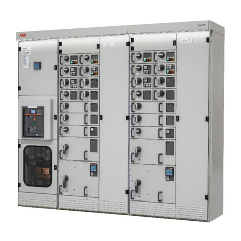
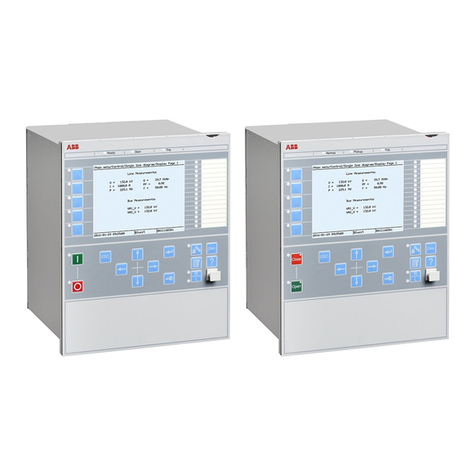
ABB Relion REB500 User manual

RELION® REB500
Distributed busbar protection REB500
Version 8.3 IEC
Communication protocol manual IEC 61850
a
=
I
;
D
e
-


a
=
I
;
D
e
-
Document ID: 1MRK 511 450-UEN
Issued: October 2020
Revision: C
Product version: 8.3
© 2019 - 2020 Hitachi Power Grids. All rights reserved

Copyright
This document and parts thereof must not be reproduced or copied without written
permission from Hitachi Power Grids, and the contents thereof must not be imparted to a
third party, nor used for any unauthorized purpose.
The software and hardware described in this document is furnished under a license and may
be used or disclosed only in accordance with the terms of such license.
This product includes software developed by the OpenSSL Project for use in the OpenSSL
Toolkit (http://www.openssl.org/). This product includes cryptographic software written/
developed by: Eric Young ([email protected]) and Tim Hudson([email protected]).
Trademarks
ABB and Relion are registered trademarks of the ABB Group. All other brand or product names
mentioned in this document may be trademarks or registered trademarks of their respective
holders.
Warranty
Please inquire about the terms of warranty from your nearest Hitachi Power Grids
representative.

Disclaimer
The data, examples and diagrams in this manual are included solely for the concept or product
description and are not to be deemed as a statement of guaranteed properties. All persons
responsible for applying the equipment addressed in this manual must satisfy themselves that
each intended application is suitable and acceptable, including that any applicable safety or
other operational requirements are complied with. In particular, any risks in applications where
a system failure and /or product failure would create a risk for harm to property or persons
(including but not limited to personal injuries or death) shall be the sole responsibility of the
person or entity applying the equipment, and those so responsible are hereby requested to
ensure that all measures are taken to exclude or mitigate such risks.
This document has been carefully checked by Hitachi Power Grids but deviations cannot be
completely ruled out. In case any errors are detected, the reader is kindly requested to notify
the manufacturer. Other than under explicit contractual commitments, in no event shall
Hitachi Power Grids be responsible or liable for any loss or damage resulting from the use of
this manual or the application of the equipment.
ABB is a registered trademark of ABB Asea Brown Boveri Ltd. Manufactured by/for a Hitachi
Power Grids company.

Conformity
This product complies with the directive of the Council of the European Communities on the
approximation of the laws of the Member States relating to electromagnetic compatibility
(EMC Directive 2004/108/EC) and concerning electrical equipment for use within specified
voltage limits (Low-voltage directive 2006/95/EC). This conformity is the result of tests
conducted by ABB Power Grids in accordance with the product standard EN 60255-26 for the
EMC directive, and with the product standards EN 60255-1 and EN 60255-27 for the low voltage
directive. The product is designed in accordance with the international standards of the IEC
60255 series.

Table of contents
Section 1 Introduction.................................................................................................... 3
1.1 This manual....................................................................................................................................3
1.2 Intended audience........................................................................................................................3
1.3 Revision history.............................................................................................................................3
1.4 Product documentation.............................................................................................................. 3
1.5 Symbols and conventions...........................................................................................................4
1.5.1 Symbols........................................................................................................................................4
1.5.2 Document conventions............................................................................................................. 4
Section 2 Safety information.........................................................................................5
Section 3 Interbay bus functions...................................................................................7
3.1 Introduction................................................................................................................................... 7
3.2 Basic configuration...................................................................................................................... 7
3.3 Configuring IEC 61850-8–1 IBB................................................................................................ 10
3.3.1 Station protection specific signals.......................................................................................10
3.3.2 Logical node GGIO (Generic process I/O) configuration..................................................11
3.3.3 Bay protection specific signals..............................................................................................13
3.4 Transfer of differential current values................................................................................... 15
3.4.1 The delta/dead band algorithm............................................................................................ 15
3.4.2 Configuring the SCS differential current parameter.........................................................15
Section 4 IEC 61850-8-1.................................................................................................17
4.1 Introduction................................................................................................................................. 17
4.2 Modeling in logical devices....................................................................................................... 17
4.3 Mapping of the REB500 signals to logical nodes.................................................................17
4.3.1 Station protection specific signals....................................................................................... 17
4.3.2 Bay protection specific signals............................................................................................. 20
4.4 Differential currents...................................................................................................................22
4.5 Disturbance recorder.................................................................................................................23
4.6 User activity events....................................................................................................................23
4.7 Service tracking (LTRK)............................................................................................................. 23
4.8 GOOSE supervision (LGOS)...................................................................................................... 24
4.9 Creation of the *.IID file.............................................................................................................24
4.10 Redundant interbay bus............................................................................................................24
4.11 Source information for LLN0.Health and LPHD.PhyHealth............................................... 24
1MRK 511 450-UEN Rev. C Table of contents
Distributed busbar protection REB500 1
Communication protocol manual IEC 61850
© 2019 - 2020 Hitachi Power Grids. All rights reserved

2

Section 1 Introduction
1.1 This manual
GUID-FD38FA69-DDD6-40C9-9185-7AC9C894B6C6 v1
The communication protocol manual describes a communication protocol supported by the
IED. The manual concentrates on vendor-specific implementations.
1.2 Intended audience
GUID-ACC7A898-5907-41E1-8DDD-DD8591298668 v1
This manual addresses the communication system engineer or system integrator responsible
for pre-engineering and engineering for communication setup in a substation from an IED
perspective.
The system engineer or system integrator must have a basic knowledge of communication in
protection and control systems and thorough knowledge of the specific communication
protocol.
1.3 Revision history
GUID-C876BDE2-918C-4B31-BA00-4D4A4190BFDC v1
1.4 Product documentation
GUID-91F0A03F-D1AF-4695-A239-1FC87E7459EE v3
REB500 manuals Document numbers
Product guide 1MRK 505 402-BEN
Application manual 1MRK 505 399-UEN
Technical manual 1MRK 505 400-UEN
Operation manual 1MRK 500 132-UEN
Engineering manual 1MRK 511 452-UEN
Commissioning manual 1MRK 505 401-UEN
Application manual for bay protection functions 1MRK 505 403-UEN
Technical manual for bay protection functions 1MRK 505 406-UEN
Cyber security deployment guideline 1MRK 511 453-UEN
Communication protocol manual IEC 61850 1MRK 511 450-UEN
Communication protocol manual IEC 60870-5-103 1MRK 511 451-UEN
Getting started guide 1MRK 505 404-UEN
1MRK 511 450-UEN Rev. C Section 1
Introduction
Distributed busbar protection REB500 3
Communication protocol manual IEC 61850
© 2019 - 2020 Hitachi Power Grids. All rights reserved
Document
revision
Date Product revision History
B 2019-07 8.3.0 First release
C 2020-10 8.3.1 Updates and extensions

1.5 Symbols and conventions
1.5.1 Symbols GUID-4F7DD10A-DEE5-4297-8697-B8AAB5E3262F v2
The electrical warning icon indicates the presence of a hazard which could
result in electrical shock.
The warning icon indicates the presence of a hazard which could result in
personal injury.
The caution icon indicates important information or warning related to the
concept discussed in the text. It might indicate the presence of a hazard which
could result in corruption of software or damage to equipment or property.
The information icon alerts the reader of important facts and conditions.
The tip icon indicates advice on, for example, how to design your project or
how to use a certain function.
Although warning hazards are related to personal injury, it is necessary to understand that
under certain operational conditions, operation of damaged equipment may result in
degraded process performance leading to personal injury or death. Therefore, comply fully
with all warning and caution notices.
1.5.2 Document conventions GUID-37C3ACF4-BD79-43C6-B37E-24B38EE69301 v3
A particular convention may not be used in this manual.
• Abbreviations and acronyms in this manual are spelled out in the glossary. The glossary
also contains definitions of important terms.
• Push button navigation in the LHMI menu structure is presented by using the push button
icons.
For example, to navigate the options, use and .
• HMI menu paths are presented in bold.
For example, select Main menu/Settings .
• Signal names are presented in bold.
The signal 21120_EXT_TEST_TRIP can be set and reset via the LHMI Test Trip menu.
• Parameter names and parameter values are presented in italics.
For example, the default value of the
Operation
setting is
Not inverted
.
• Section references are presented with the respective section numbers.
For example, see Section 1.5.2 for more details about document conventions.
Section 1 1MRK 511 450-UEN Rev. C
Introduction
4Distributed busbar protection REB500
Communication protocol manual IEC 61850
© 2019 - 2020 Hitachi Power Grids. All rights reserved

Section 2 Safety information
GUID-7CDA9FB7-5CD6-4BD5-A1D2-AAB8E7BF87A3 v3
Dangerous voltages can occur on the connectors, even though the auxiliary
voltage has been disconnected.
Non-observance can result in death, personal injury or substantial property
damage.
Only a competent electrician is allowed to carry out the electrical installation.
National and local electrical safety regulations must always be followed.
The frame of the IEDs has to be carefully earthed.
Whenever changes are made in the IEDs, measures should be taken to avoid
inadvertent tripping.
The IEDs contain components which are sensitive to electrostatic discharge.
Unnecessary touch of electronic components must therefore be avoided.
1MRK 511 450-UEN Rev. C Section 2
Safety information
Distributed busbar protection REB500 5
Communication protocol manual IEC 61850
© 2019 - 2020 Hitachi Power Grids. All rights reserved

6

Section 3 Interbay bus functions
GUID-FC8C1289-F943-4E92-A50E-BDA7281A5337 v1
3.1 Introduction
GUID-7A41F2A2-F366-4D30-9D76-BB6279380110 v3
An interface is available for connecting the numerical busbar protection to a station
automation system or station monitoring system (SCS/SMS).
For an overview of REB500’s communication interfaces, see the
Operation manual
.
In contrast to feeder control and protection bay units, REB500 is equipped with only a single
interbay bus interface via which all the REB500 bay units in the entire station communicate.
This has to be taken into account by the various bus protocols.
This document applies for IEC 61850-8-1. However, Section 3 of this document
also contains information of a second IBB using IEC 60870-5-103 if configured.
3.2 Basic configuration
GUID-B10CC299-040D-453F-B876-52AB342E9001 v3
The dialog box for configuring the communication is accessed by selecting the menu HMI500
Configuration/Communication/SCS Configuration.
15000028-IEC18000554-1-en.vsdx
IEC18000554 V1 EN-US
Figure 1: Dialog box for configuring the communication
1MRK 511 450-UEN Rev. C Section 3
Interbay bus functions
Distributed busbar protection REB500 7
Communication protocol manual IEC 61850
© 2019 - 2020 Hitachi Power Grids. All rights reserved

Table 1: Configuration of IEC 61850-8-1
Setting Description Default setting
IED Name 61850 Name of the REB500 IED REB500
RCB’s buffered 61850 report control blocks transfer
mode (for communication with third-
party systems). Measurements always
transferred unbuffered
None
Fill the Report ID For compatibility reasons with older
61850 servers (for example, Siemens) the
field could be activated in the
communication dialog
None
Edition 1/ Edition 2 Radio button which determines the
61850 model version
Edition 1
Import GOOSE
signals
Action button which opens the import
SCD file dialog
Update Subst.
Config file
Action button which opens the reimport
SCD file dialog
GOOSE enabled /
disabled
Check box which indicates whether
GOOSE inputs are used or not
No checked
Subst. Config file Filename and path of the imported
Substation Configuration File (SCD)
Enable Goose send Checkbox which indicates whether
GOOSE send for tripping is enabled or
not
No checked
GCB configuration Action button which opens the GOOSE
control block configuration dialog box
The dialog box for Ethernet communication settings is accessed by selecting the menu
HMI500 Configuration/Communication/Ethernet Devices.
18000075-IEC18000798-1-en.vsdx
IEC18000798 V1 EN-US
Figure 2: Dialog box for Ethernet communication settings
Section 3 1MRK 511 450-UEN Rev. C
Interbay bus functions
8Distributed busbar protection REB500
Communication protocol manual IEC 61850
© 2019 - 2020 Hitachi Power Grids. All rights reserved

Table 2: Configuration Ethernet communication
Setting Description Default setting
IP address IEC 61850-8-1 TCP/IP Address 0.0.0.0
Subnet mask IEC 61850-8-1 TCP/IP Subnet Mask 0.0.0.0
Gateway address IEC 61850-8-1 TCP/IP Gateway Address 0.0.0.0
The dialog box for configuring the communication is accessed by selecting Time in the
HMI500 Setting menu.
13000022-IEC18000461-1-en.vsdx
IEC18000461 V1 EN-US
Figure 3: Dialog box for configuring time zone correction
13000034-IEC18000462-1-en.vsdx
IEC18000462 V1 EN-US
Figure 4: Dialog box for configuring daylight saving time settings
1MRK 511 450-UEN Rev. C Section 3
Interbay bus functions
Distributed busbar protection REB500 9
Communication protocol manual IEC 61850
© 2019 - 2020 Hitachi Power Grids. All rights reserved

13000023-IEC18000607-1-en.vsdx
IEC18000607 V1 EN-US
Figure 5: Dialog box for configuring time synchronization
Table 3: Configuration of IEC 61850-8-1 time synchronization
Setting Description Default setting
Time zone correction
(h/m)
Time zone setting (hours/minutes) See Screenshot
Daylight saving time Dialog for switching from standard time to
summertime and vice versa
See Screenshot
SNTP SNTP must be used as time source if 61850 is
used
None
UTC UTC must be selected if 61850 is used No
SNTP1 TCP/IP Address of the SNTP time master 127.0.0.1
SNTP2 TCP/IP Address of the SNTP standby time
master
127.0.0.1
3.3 Configuring IEC 61850-8–1 IBB
3.3.1 Station protection specific signals GUID-39D6617C-7870-4A9B-A05F-E7DA895A61CD v3
For IEC 61850, all important station protection specific signals are mapped automatically to
the 61850 Model (see Section 4.3.1). This is done by the HMI500 tool automatically and cannot
be changed manually. This is shown by an inactive tick check box for IBB 1 or IBB 2,
respectively.
The logical Node and the name of the data attribute of a mapped signal are shown in the IEC
61850-8-1 box. The IEC 61850-8-1 box is not shown for signals which are not transferred to the
SCS/SMS.
Section 3 1MRK 511 450-UEN Rev. C
Interbay bus functions
10 Distributed busbar protection REB500
Communication protocol manual IEC 61850
© 2019 - 2020 Hitachi Power Grids. All rights reserved

13000024-IEC18000608-1-en.vsdx
IEC18000608 V1 EN-US
Figure 6: Configuring signals as events
Diagnostic and system events are always available for transfer whichever protocol is in use
and cannot be configured.
The IEC 60870-5-103 section only appears when the protocol is configured.
3.3.2 Logical node GGIO (Generic process I/O) configuration
GUID-49BCE444-5FF8-4226-800B-E1399532950B v3
Signals, which are not mapped to the IEC 61850 Model by the HMI500 tool automatically, can
only be transferred to SCS/SMS indirectly. They have to be assigned to binary I/Os first.
The binary I/Os are represented by the logical node GGIO in the 61850 model. By default, no
signals are mapped to the GGIO logical node.
The mapping configuration is opened by selecting the CR channel and pressing button CR
event config, OC channel and OC event config for binary inputs, respectively.
1MRK 511 450-UEN Rev. C Section 3
Interbay bus functions
Distributed busbar protection REB500 11
Communication protocol manual IEC 61850
© 2019 - 2020 Hitachi Power Grids. All rights reserved

15000025-IEC18000609-1-en.vsdx
IEC18000609 V1 EN-US
Figure 7: Configuring I/Os as GGIO
Leading and lagging edges shall be ticked. The IBB which is configured for IEC 61850-8-1 shall
be ticked.
The User defined text can be changed to identify the signal in the 61850 client tool.
15000026-IEC18000610-1-en.vsdx
IEC18000610 V1 EN-US
Figure 8: Configuring GGIO description
Table 4: Configuration Ethernet communication
Setting Description Default setting
No recording
at the leading edge recorded on the positive going edge No
at the leading edge recorded on the negative going edge No
Table continues on next page
Section 3 1MRK 511 450-UEN Rev. C
Interbay bus functions
12 Distributed busbar protection REB500
Communication protocol manual IEC 61850
© 2019 - 2020 Hitachi Power Grids. All rights reserved
Setting Description Default setting
User defined text Bin_Out_Channel
Bin_In_Channel
Default text
Send event to At least one event memory must be selected
IBB x Events can be assigned to the event lists of
interbay bus (IBB) 1 and/or 2
No
External MMC
connected to central
unit
Events are stored in the CU memories No
External MMC
connected to bay unit
Events are stored in the BU memories No
IEC Function Type Used for IEC 60870-5-103 0
IEC Information Number Used for IEC 60870-5-103 0
The User defined text is shown in the Description data attribute of the 61850 client.
17000041-IEC18000611-1-en.vsdx
IEC18000611 V1 EN-US
Figure 9: 61850 client description view of GGIO data attribute
3.3.3 Bay protection specific signals GUID-C83A48D6-735E-4DEA-A86F-895FD037B1C1 v3
For IEC 61850, bay protection specific signals are not mapped automatically to
the 61850 Model (see Section 4.3.2). Only those bay protection binary signals
can be configured to be recorded as events which are also configured via HMI
menu Configuration /Binary module .
This implies the following configuration steps:
1. Assignment of Logical output signals.
Only bay protection logical output signals that are configured to one of the 120 Logical
output of BP part (see
Application Manual for Bay Protection
, Section
Communication
,
table
Cross-references/ Item1
) can be seen in a 61850 client as spontaneous data change.
For details about the configuration of the bay protection specific output signals to the
General Purpose BP outputs, see
Application Manual for Bay Protection
, Section
Communication
, table
Cross-references/ Item2
.
2. Adjustment of the Binary module configuration.
The signal must appear in the Outputs Overview tab of the Binary module configuration
dialog box (see
Operation Manual
, Section
Outputs overview tab
).
Output signals do not necessarily have to be assigned to output relays.
The Name logical Node is composed by the following elements:
1MRK 511 450-UEN Rev. C Section 3
Interbay bus functions
Distributed busbar protection REB500 13
Communication protocol manual IEC 61850
© 2019 - 2020 Hitachi Power Grids. All rights reserved

Table 5: Composing logical node name for bay protection
Element Example for
OCINST
Field Comment
Function no. IEEE F50 Prefix
Phase Lx / N0 Prefix Omitted if three phase protection
Logical node name PTOC lnClass Time overcurrent function
Instance 7 inst the unique instance number of the
BP function
Description desc User specific description of the BP
function of the instance
17000042-IEC18000612-1-en.vsdx
IEC18000612 V3 EN-US
Figure 10: 61850 client BP logical node name
Table 6: Composing description of the data attribute
Element Example for OCINST.Str,general Comment
Bay name AJK47
Delimiter . full stop
BP Signal name 226705_OCINST Start
Delimiter . full stop
Instance 7 the unique instance number of the
BP function
17000043-IEC18000614-1-en.vsdx
IEC18000614 V3 EN-US
Figure 11: 61850 client description view of BP data attribute
The name of the data attribute of a mapped signal is shown in the IEC 61850-8-1 box of the
Outputs Details tab (see
Operator Manual
, Section
Outputs Details tab
). The IEC 61850-8-1
box is not shown for signals which are not transferred to the SCS/SMS.
Section 3 1MRK 511 450-UEN Rev. C
Interbay bus functions
14 Distributed busbar protection REB500
Communication protocol manual IEC 61850
© 2019 - 2020 Hitachi Power Grids. All rights reserved
Other manuals for Relion REB500
17
Table of contents
Other ABB Industrial Equipment manuals
Popular Industrial Equipment manuals by other brands

Aventics
Aventics DDL-X-Tool Assembly instructions

Spartan
Spartan TE200 Series user manual

Siemens
Siemens SIVACON 8PS BD2 Series installation instructions

Blohm + Voss Oil Tools
Blohm + Voss Oil Tools FloorHand 9GF-1102 Technical documentation
PCM
PCM VDF-401 operating instructions

Atlas Copco
Atlas Copco ZT 55 VSD Instruction book