ABB UniGear ZS1 Manual

• Safety
• Reliability
• Flexibility
• Economy
—
INSTALLATION, OPERATION AND MAINTENANCE INSTRUCTION MANUAL
UniGear ZS1
with a panel width of 500 mm

2

—
Table of Contents
Your safety first – at all times!
1. Summary
2. Technical data
3. Panel design and equipment
4. Dispatch and storage
5. Assembly of the switchgear at site
6. Operation of the switchgear
7. Commissioning
8. Maintenance
9. Product quality and environmental protection
04
05
06
07
18
22
42
47
48
52

4UniGear ZS1 INSTALLATION, OPERATION AND MAINTENANCE
—
Your safety first – at all times!
That is why our instruction manual begins
with thefollowing recommendations:
• Only install switchgear in closed rooms suitable
for electrical equipment
• Ensure that installation, operation and
maintenance are only carried out by qualified
competent electricians only
• Fully comply with the legally recognized
standards (IEC or local), the connection
conditions of the local electrical utility and
the applicable safety at work regulations
• Observe the relevant information in the
instruction manual for all actions involving
switchgear
Danger!
Pay special attention to the hazard notes
in the instruction manual marked with this
warning symbol.
• Make sure that the specified data are not
exceeded under switchgear operating
conditions
• Keep the instruction manual accessible to all
personnel involved in installation, operation
and maintenance
• The user’s personnel must act responsibly in
all matters affecting safety at work and correct
handling of the switchgear
Warning
Always follow the instruction manual and
respect the rules of good engineering
practice!
Hazardous voltage can cause electrical
shocks and burns.
Disconnect power, then earth and
shortcircuit before proceeding with any
work on this equipment.
Warning
Using of safety clothes like safety gloves
according to EN 388 Blade cut resistance
class 5, long sleeved work jacket or safety
sleeves, safety shoes is recommended
during all activities done with the
switchgear.
If you have any further questions about this
instruction manual, the members of our field
organization will be pleased to provide the
required information.
We reserve all rights to this publication.
Misuse, and including in particular, duplication
and making this manual - or extracts thereof
available to third parties is prohibited. We do not
accept any responsibility for the informations
provided, which are subject to change.

5SUMMARY
—
1 Summary
1.1 General
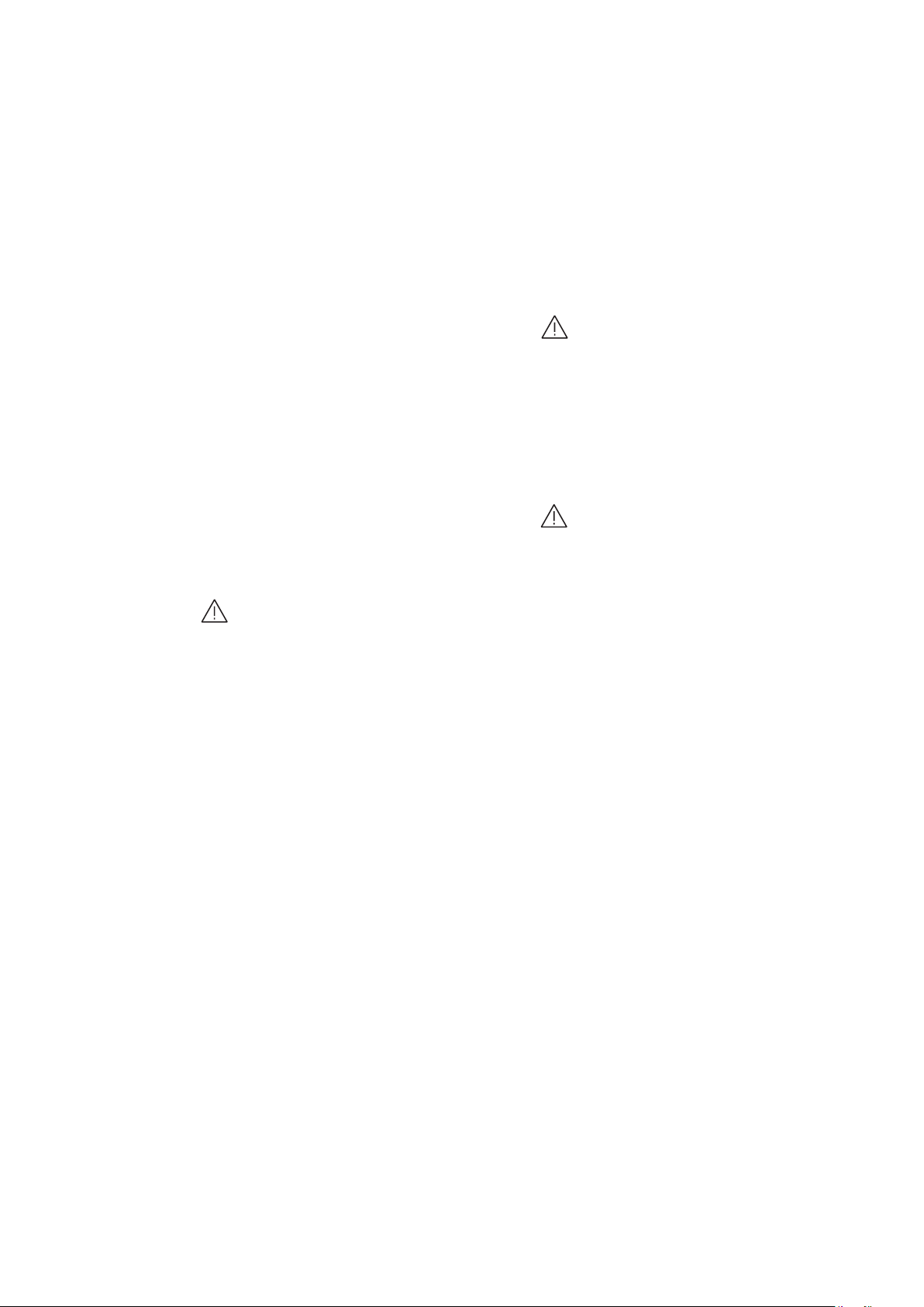
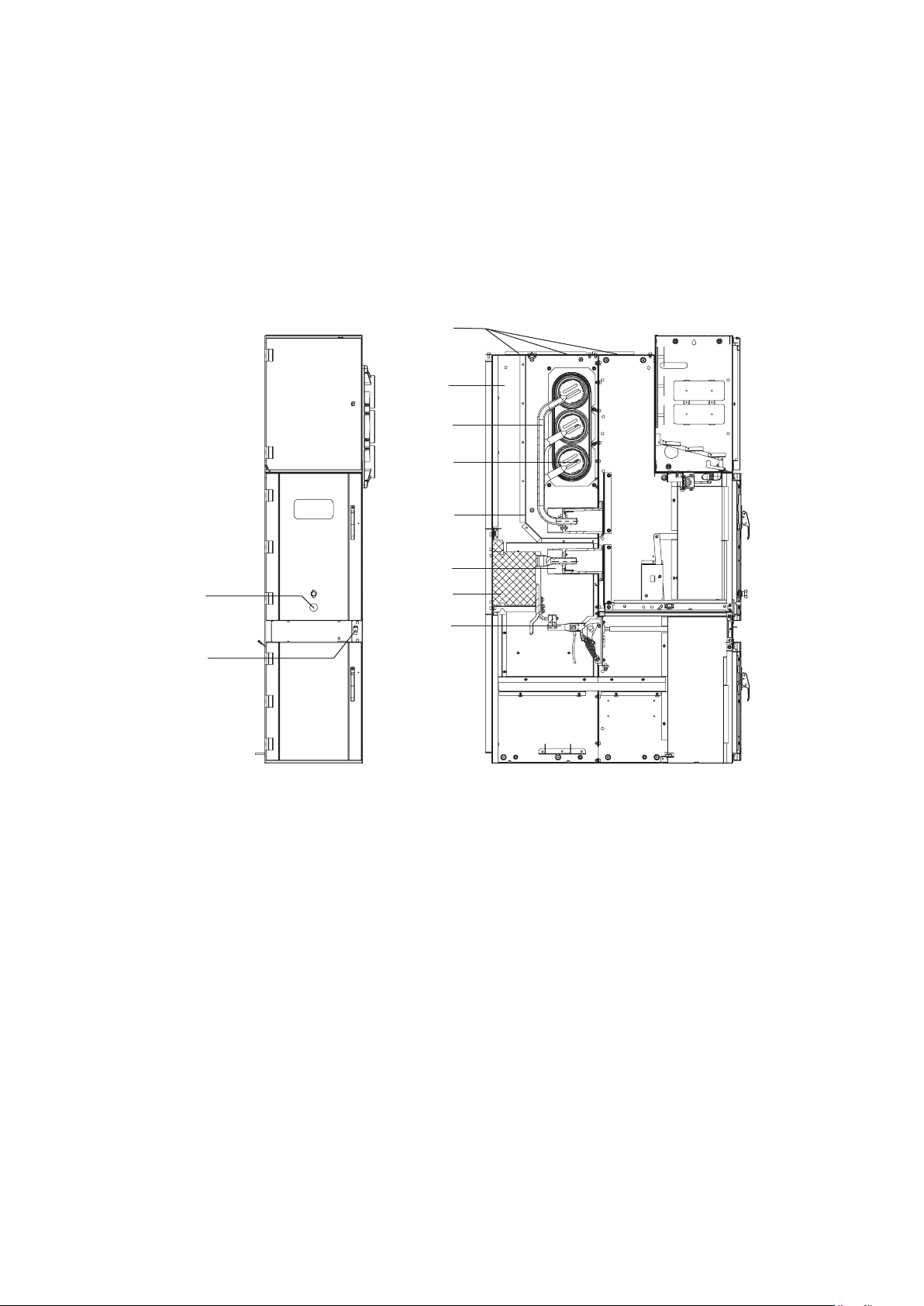
UniGear ZS1 is a three-phase, metal-enclosed, air
insulated switchgear that is factory-assembled,
type tested and suitable for indoor applications up
for 12 kV. The units are designed to accommodate
withdrawable modules and are fitted with a
single busbar system. The withdrawable parts
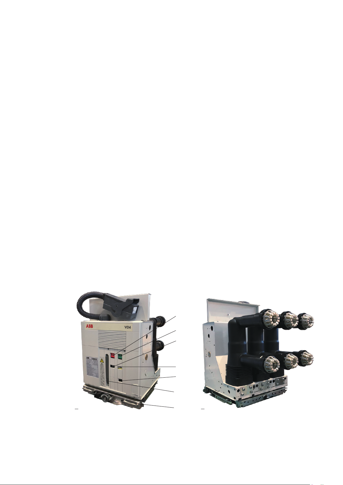
are equipped with circuit-breakers. Details of the
technical design and configuration of individual
switchgear, including detailed equipment lists
for the individual panels and comprehensive
circuit documentation etc. can be found in the
relevant order documents.
1.2 Standards and specifications
UniGear ZS1 switchgear panels comply with the
standards and specifications for factory-
assembled, metal-enclosed and type-tested high
voltage switchgear, i.e. IEC publications 62271-200
and 62271-1. In addition, in accordance with IEC
60529, the switchgear panels have the following
degrees of protection: IP4X for the enclosure and
IP2X for the partitions.
All other corresponding IEC publications, national
or local safety at work regulations and safety
regulations for production materials must be
followed during the installation and operation of
these systems. Above and beyond this, the order-
related data from ABB must be taken into account.
1.3 Operating conditions
1.3.1 Normal operating conditions
The switchgear is basically suitable for normal
operating conditions for indoor switchgear in
accordance with IEC 62271-200. Among other
considerations, the following limiting values
apply.
The normal operational altitude is up to 1,000 m
above sea level.
The indoor ambient conditions are free of
significant pollution, such as dust, smoke,
corrosive and/or flammable gases, vapors or
salt, etc.
1.3.2 Special operating conditions
The switchgear is suitable for operation in the
WDa type of climate according to IEC 60721-2-1.
Special operating conditions must be discussed
with ABB in advance. For example:
• At site altitudes above 1,000 m, the effects of
the reduction in dielectric strength of the air on
the insulation level must be taken into account
(please refer to the diagram in Figure 1)
• Increased ambient temperatures must be
compensated in the design of the busbars and
branch conductors, otherwise the current
carrying capacity will be limited
Note on special climatic operating conditions:
When switchgear is operated in areas with high
humidity and/or major rapid temperature
fluctuations, there is a risk of dew deposits
which must be excluded under normal operating
conditions for indoor switchgear.
Preventive action (e.g. suitable ventilation and
proper air conditioning of the building or housing,
use of dehumidifying equipment, etc.) must be
taken into consideration with ABB to avoid this
condensation phenomenon and any resulting
corrosion or other adverse effects.
Ambient temperature:
• Maximum +40 °C
• Maximum 24 h average +35 °C
• Minimum (according to “minus indoor class”) -15 °C
Ambient humidity:
Maximum 24 h average of relative humidity 95% RH
Maximum 24 h average of water vapour pressure 2.2 kPa
Maximum monthly average of relative humidity 90% RH
Maximum monthly average of water vapour pressure 1.8 kPa
k 1,0
0,8
0,6
0,4
1000 2000 3000 4000 m 5000 H

—
2 Technical data
2.1 Electrical data
1) Up to 4000 A if coupled with other UniGear ZS1 units.
1) Height of the control cabinet is 705/900 mm.
2) Deeper units are available on request.
6UniGear ZS1 INSTALLATION, OPERATION AND MAINTENANCE
2.2 Resistance to internal arc faults
The fault withstand capacity is 31.5 kA for 1 s.
The switchgear units have been tested
according to IEC 62271-200 standard (Annex A,
accessibility type A, IAC classification FLR) and
also to PEHLA recommendation No.4. In
individual cases, depending on the
configuration of the switchgear panels and/or
the switchroom conditions (e.g. low ceiling
height), additional measures may be necessary
to ensure compliance with criterion 5.
IEC
12
12
28
75
50/60
...31.5
80
...31.5
...4000
630-1250
GB
12
12
42
75
50/60
...31.5
80
...31.5
...4000
630-1250
kV
kV
kV 1 min
kV
Hz
kA 3 s
kA
kA 1 s
A
A
Rated voltage
Rated insulationvoltage
Rated power frequency withstand voltage
Rated lightning impulse withstand voltage
Nominal frequency
Rated short-time withstand current
Peak curent
Internal arc withstand current
Main busbars rated current 1)
Branch connections rated current
Dimension (mm) Weight (includes withdrawable modules)
Height A 2200/2595 1)
610-850 kg
Width
- Feeder panel B 500
Depth C 2) 1310/1620
Height of the basic part of panel D 2100
E 1495
2.3 Dimensions and weights

—
3 Panel design and equipment
3.1 Basic structure and variants
The UniGear ZS1 panel uses insertion technology
for the incoming/outgoing feeder panel with a
vacuum circuit-breaker. Each UniGear panel
consists of three high-voltage compartments -
busbar, circuit-breaker and cable connection -
while a control cabinet houses the secondary
equipment. Apart from this, variants are possible
for all operating needs.
Figure 2 shows example of possible panel
configuration, including electrical equipment.
For busbar sectioning, two panels are necessary: a
coupling panel with the withdrawable circuit-
breaker part and a bus-riser panel (optional with
busbar metering and earthing).
Further details about installation and switchgear
equipment can be ordered from the manufacturer.
3.2 Enclosure and partitioning
A typical panel enclosure is made of 2 mm thick
high quality galvanized steel sheets. The internal
partitions consist of 2 mm thick high quality
galvanized steel or stainless steel sheets. The
materials used protect the panel against rust
and oxidation under adverse circumstances.
The three high-voltage compartments are
equipped with top-mounted and secured
pressure-relief flaps which are opened (by a
shockwave) to release the pressure and gas
buildup caused by an internal arc fault. The
pressure-relief flaps are secured with steel screws
on one longitudinal side and plastic screws on
the other side. The internal overpressure causes
the plastic screws to rupture.
The front of the panel is closed off by pressure
resistant doors. The cable and circuit-breaker
compartments have their own doors. Neighboring
panels are separated from one another by the side
walls of each panel, and an air cushion remains
between these walls when the panels are jointed
together.
Limiting, or even avoiding the end effects of an
internal arc fault is dependent on ceiling height,
and in individual situations, some special protection
measures are needed.
• The mounting of a pressure relief duct on the
top of the switchgear, with further channels
leading out of the switchgear room in a form
appropriate to the design of the building. The
shock wave and arc discharge are channeled
off in ducts
• A switchgear internal arc causes the air pressure
inside a compartment to rise. Meanwhile the
doors are closed and sealed, causing the high
air pressure to burst through the pressure
release plate and out through the top of the
switchgear
• Steel plates are used to separate the low-and
high-voltage compartments
• The switchgear end covers are designed not
only for aesthetic purposes but their mechanical
and electro-caloric properties provide good
protection when an internal fault arc occurs
7PANEL DESIGN AND EQUIPMENT

1 Enclosure
1.1 Pressure relief flap
2 Branch conductor
3 Busbar
5 Isolating bushing
6 Earthing switch
7 Current transformer
8UniGear ZS1 INSTALLATION, OPERATION AND MAINTENANCE
18
1.1
1
2
3
84
5
7
6
18.1
18.2
14
14.1
14.2
14 Earthing switch operating mechanism
14.1 Operating shaft for earthing switch
14.2 Slide
18 Spindle mechanism
18.1 Spigot on spindle
18.2 Hole in spindle for insertion lever
84 Partition
—
Figure 2-1 Example of UniGear ZS1 unit

3.3 Panel compartments
3.3.1 Busbar compartment
The main busbars are either flat or D-shaped and
are made of copper. They are laid in sections from
panel to panel.
According to the current rating, either a single
or double configuration is used. They are held
in place by branch conductors, and if installed, by
busbar bushings. No special connection clamps
are needed. The bolt connections in the busbar
system have insulating covers. By means of
bushing plates and busbar bushings, partitions
can be created between panels. These
partitions are necessary for every panel.
3.3.2 Circuit-breaker compartment
The circuit-breaker compartment (Fig. 3, 4)
contains all the necessary equipment that
allows the withdrawable part and the panel to
work seamlessly together. Like the busbar
compartment, it is metallically partitioned on
all sides. The isolating contacts and the fixed
isolating contacts are located on a mounting
plate. The metal shutters covering the insertion
openings are also included. The shutters are
automatically opened by the actuating bars of
the withdrawable circuit-breaker part when, by
means of a lever, it is set up in the service position.
The shutters are closed when the withdrawable
part is moved to the test/disconnected position.
When the withdrawable part is in the test/
disconnected position inside the panel,
partitioning by separation is established in the
main current circuit. Connection of the control
wiring, required for test purposes, is not
interrupted when in the test/disconnected
position. The socket for the control wiring is
mounted inside the circuit-breaker compartment.
In the test/disconnected position, the ON/OFF
pushbutton located on the circuit-breaker, and
the mechanical indicators for ON/OFF and
CHARGED/DISCHARGED can be observed through
an inspection window. All switching operations
are carried out with the doors closed. Installation
of an additional mechanical switching device to
manually operate the circuit-breaker in the service
position is also possible.
9PANEL DESIGN AND EQUIPMENT
—
Figure 3-1 Circuit-breaker compartment, open.
Withdrawalpart in the disconnected
position
10.1 Control wiring socket
12.1 Top shutter
12.2 Lower shutter
14 Earthing switch operating mechanism
14.1 Drive shaft
42 Right travel rail
43.3 Duct cover, top right
—
Figure 4 View into the circuit-breaker compartment
10.1
12.1
43.3
12.2
42
14
14.1

10 UniGear ZS1 INSTALLATION, OPERATION AND MAINTENANCE
3.3.3 Withdrawable parts
1) Withdrawable circuit-breaker parts:
The withdrawable part of the UniGear ZS1
panel forms a complete module consisting of
the vaccum circuit-breaker type VD4 (Fig. 5,
6), an isolated contact arm with its associated
contact system and a control wiring plug.
The withdrawable assembly and the circuit-breaker
are coupled via a multi-pole control wiring plug
connector. The withdrawable assembly establishes
the mechanical connection between the panel and
the circuit-breaker. The fixed part of the assembly
is connected, on both sides, to the panel by
form-coded forking. The moving part with the
circuit-breaker is moved manually between the
service or test/disconnected positions - with
the front doors closed - by means of a spindle.
Auxiliary switches are used to register both the
selected position and the angular position of the
spindle.
The withdrawable part and the panel are earthed
together by means of an earthing system in the
panel.
Withdrawable parts with the same design are
interchangeable. In cases where the dimensions
are identical but the circuit-breaker fittings differ,
the control wiring plug coding (Fig. 16) prevents
incorrect connections between the withdrawable
part and the panel. Detailed coding information
is given in the relevant order documents.
2) Other withdrawable parts include:
• The metering voltage-transformer truck with
fuses
• The earthing truck without making capacity
(for the main busbar system and power
cables)
• The power cable testing truck
• The isolation truck
• The metering truck
13.1 – Close pushbutton
13.2 – Open pushbutton
13.4 – Signaling device for circuit-breaker open/closed
13.5 – Operation counter
13.4 – Signaling device for closing springs charged/discharged
13.15 – Withdrawal part
28a – Lever for manually charging the closing springs
—
Figure 5 VD4 circuit breaker
—
Figure 6 VD4 circuit-breaker pole side
13.2
13.1
13.4
13.8
13.5
28a
13.15

11PANEL DESIGN AND EQUIPMENT
3.3.4 Cable connection compartment
Depending on individual operating requirements,
the cable compartment can house up to three
current transformers, fixed and withdrawable
voltage transformers, and an earthing switch.
Should all three current transformers not be
required, dummies are installed in their place using
the same installation and connection procedures.
The fix-mounted voltage transformers are
connected on the primary side with flexible,
full-insulated cables that are inserted into the
transformers.
The removable voltage transformers are fitted
with HRC fuses.
The ET1 earthing switch can be used with a
manual mechanism. Its switching position is
indicated mechanically by an indication on the
shaft and electrically by means of the auxiliary
switch.
The surge arrestors can be fix-mounted in the
cable compartment.
Cable connection of units:
• As a standard solution, it is possible to
connect up to three parallel plastic cables with
single-core protection per phase.
In a 1,250 A panel, the cable push-on sealing ends
require a maximum cross section of 300 mm2
• Customer requests regarding connections to
bars, three-core cables, special cables or sealing
ends of different types must be considered
during the order-planning stage
—
Figure 7 Low-voltage compartment, internal view
For more information regarding cable connections,
please refer to chapter 5.10.
3.3.5 Control cabinet
The control cabinet, which covers all control and
protection aspects, can accommodate both
conventional or microprocessor control technology.
If the secondary devices are not intended for door
installation they are mounted on DIN RAILS.
These rails enable any subsequent changes to the
wiring. Three rows of DIN RAILS on a swiveling
DIN RAIL holder are located at the lower part of
the control cabinet, and directly under these is an
easily accessible auxiliary switch for the control
wiring plug.
The secondary wiring inside the panel is housed
in a duct on the right side of the panel. The
left-hand side of the panel is for the external
wiring. The ducts are covered with a steel metal
sheet. Holes at the side of the control cabinet
enable the ring conductors to be slid in.

12 UniGear ZS1 INSTALLATION, OPERATION AND MAINTENANCE
3.4 Interlock/protection against incorrect
operation
All interlocking features are realized mechanically
or through an electrical interconnection.
3.4.1 Panel internal interlocking
To prevent hazardous situations and incorrect
operation, there is a series of interlocks to protect
both personnel and equipment.
• The withdrawable part can only be moved from
the test/disconnected position (and back)
when the circuit- breaker and earthing switch
are off. In the intermediate position, the switch
is mechanically interlocked. The interlock is
electrical if the circuit breaker features an
electrical release
• The circuit breaker can only be switched on
when the withdrawable part is in the test or
service position. In the intermediate position,
the switch is mechanically interlocked. The
interlock is electrical if the circuit-breaker
features an electrical release
• In the service or test positions, the circuit
breaker can only be switched off manually
when no control voltage is applied and it cannot
be closed (electromechanical interlock)
• Connecting and disconnecting the control wiring
plug is only possible when the withdrawable
part is in the test/disconnected position
• The earthing switch can only be switched on
if the withdrawable part is in the test/
disconnected position or outside of the panel
• If the earthing switch is on, the withdrawable
part cannot be moved from the test/disconnected
position to the service position
• Details of possible interlocks, for example in
connection with a locking magnet on the
withdrawable part and/or an earthing switch
drive, can be obtained from the relevant order
document
3.4.2 Interlocking doors
• The withdrawable parts cannot be racked in
if the apparatus compartment door is open
(Fig. 8, 9)
• The apparatus compartment door cannot be
opened if the apparatus is in service or in an
undefined position (Fig. 10, 11)
• The earthing switch cannot be operated if the
cable compartment door is open (Fig. 12, 13)
• The cable compartment door cannot be opened
if the earthing switch is open (Fig. 14, 15)
3.4.3 Interlocks between panels
• The busbar earthing switch can only be closed
when all the withdrawable parts in the relative
busbar section are in the test/disconnected
position (electrical interlock)
• When the busbar earthing switch is closed, the
withdrawable parts in the earthed busbar section
cannot be moved from the test/disconnected
position to the service position
(electromechanical interlock)
3.4.4 Locking devices
• The shutters can be secured independently of
each other with a mechanical lock when the
withdrawable circuit-breaker part has been
removed
• Access to the operating shaft of the earthing
switch can be restricted using a padlock (or
keylock)
• Access to the circuit-breaker racking slot, the
circuit-breaker compartment and the cable
compartment can be restricted using a padlock
(or keylock)

13PANEL DESIGN AND EQUIPMENT
Types of interlocks
Standard safety interlocks (mandatory)
Keys (on request)
Padlocks
Locking magnets (on request)
Accessory devices
Type
1
2
3
4
5
Description
Apparatus racking-in/out
Apparatus closing
Apparatus racking-in
Apparatus multi-contact plug unplugging
Earthing switch closing
Apparatus racking-in
Apparatus compartment door opening
Apparatus racking-in
Feeder compartment door opening
Earthing switch opening
6
7
8
9
10
Apparatus racking-in lock
Earthing switch closing lock
Earthing switch opening lock
Insertion of the apparatus raking-in/out crank lever
Insertion of the earthing switch operating lever
Condition to be fulfilled
Apparatus in OFF position
Defined truck position
Apparatus multi-contact plug plugged
Truck in test position
Earthing switch in OFF position
Truck in test position
Apparatus compartment door closed
Earthing switch in OFF position
Cable compartment door closed
Can only be removed with the truck in the racked-out position.
Can only be removed with the earthing switch open.
Can only be removed with the earthing closed.
Can always be removed.
11
12
13
14
15
Apparatus compartment door opening
Cable compartment door opening
Insertion of the apparatus raking-in/out crank lever
Insertion of the earthing switch operating lever
Shutters opening or closing
16
17
Apparatus racking-in/out
Earthing switch ON/OFF
Magnet energized.
Magnet energized.
20
21
22
Shutters fail-safe
Apparatus-switchgear unit compatibility matrix
Circuit-breaker mechanical operating mechanism
The device locks the shutters in the closed position when the
apparatus is removed from the compartment. The operator
cannot open the shut ters manually. The shutters can only be
operated by the apparatus truck.
The apparatus multi-contact plug and relative switchgear unit
socket are equipped with a mechanical matrix, that disables
apparatus racking-in into a switchgear unit with an
inappropriate rated current.
The apparatus compartment is equipped with a mechanical
device, that enables circuit-breaker closing and/or opening
directly by means of the front operating mechanism pushbuttons,
keeping the door closed. The controls can be operated with the
circuit-breakers in the operation and racked-out position.
A
B
A
B
A
B
A
B
A
B
Note: Apparatus is circuit-breaker.
It is necessary to use padlocks with 5-8 mm hasp diameter.

14 UniGear ZS1 INSTALLATION, OPERATION AND MAINTENANCE
—
Figure 10 Circuit- breaker compartment door locking device
—
Figure 9 Circuit- breaker truck enabling slot
—
Figure 8 Circuit- breaker compartment door enabling device

15PANEL DESIGN AND EQUIPMENT
Pin ON Pin OFF
Note: It’s not suitable for floor rolling version.
—
Figure 13 Cable compartment door enabling slot and earthing switch enabling pin
—
Figure 11 Circuit-breaker compartment door locking device
—
Figure 12 Cable compartment door enabling device

16 UniGear ZS1 INSTALLATION, OPERATION AND MAINTENANCE
—
Figure 14 Cable compartment door locking device
—
Figure 15 Cable compartment door locking device

17PANEL DESIGN AND EQUIPMENT
3.5 Circuit-breaker plug connector coding
The control wiring plug connector coding allows
the withdrawable parts for switching devices
to be assigned to particular panels. This ensures
that withdrawable parts with different rated
currents or different control wiring circuits can
only be used in the panels they are intended for.
Coding pins are fitted in the control wiring sockets
10.1 or control wiring plugs 10.2, and engage with
the corresponding bores of the relevant plug 10.2
or socket when the two parts are connected.
The plug connector coding is order-related, and
is noted in the relevant wiring documentation.
Coding:
(…) The corresponding coding designation for
the control wiring plug is given in brackets.
The coding pins can be fitted in the control wiring
socket and/or in the control wiring plug.
– Basic design
The number of sockets is optional but the basic
assignment is 1, 8, 10, 20, 21, 31, 33 and 40.
Sockets and pins can be mixed as required in the
control wiring socket and control wiring plug.
3.6 Ith Limitors
It is additional safety feature on the top of each
unit. The microswitch generates an immediate
fault signal when the overpressure flap is opened.
Reaction time is less then 15 ms. The signal from
the microswitch can be sent directly to trigger
the circuit-breaker OFF.
10.5 10.4
10.4
10.1
10.1 – Control wiring socket
10.4 – Centering striking tabs
10.5 – Bore for actuating pin of the control wiring
plug for controlling the auxiliary switch
11.5
It may be necessary to move the auxiliary switches into their service
position when the lifting eyebolts have been removed.
11.5 Ith limiter
The centre of the switch knob of the auxiliary switch must be
adjusted to the centre of the pressure relief flap hole.
49.2 Pressure relief flap
11.5
49.2
—
Figure 16 Control wiring plug connector coding
—
Figure 17 Auxiliary Ith limiter switch

30 1.5 ≥60°
1.5 lifting eyebolt
18 UniGear ZS1 INSTALLATION, OPERATION AND MAINTENANCE
—
4 Dispatch and storage
4.1 Condition on delivery
At the time of dispatch, the UniGear panels are
factory-assembled, the withdrawable parts are
in the test position and the doors are closed.
The factory-assembled panels are checked at the
works for completeness in terms of the order and
simultaneously subjected to routine testing
(normally without AC voltage testing of the
busbars) to IEC publication 62271-200, and are
therefore tested for correct structure and function.
The busbars are not assembled. The busbar
material, fasteners and accessories are packed
separately.
4.2 Packing
Available manners of packing:
• Polythene foil - storage time 1/2 year in clean
and dry environment
• OSB boards - storage time 1/2 year in outdoor
environment according to IEC
• Wood boxes - storage time 1 year in outdoor
environment according to IEC
According to the kind of transport and country
of destination, the panels remain unpacked or
packed in seaworthy crates. A drying agent is
provided to protect them against moisture.
• Panels with basic packing or without packing
• Panels with seaworthy or similar packing
(including packing for containerised shipments):
- Sealed in polyethylene sheeting
- Transport drying agent bags included
4.3 Transport
The transport units normally comprise two
panels and, in exceptional cases, small groups of
panels. The panels are each fitted with four lifting
eyebolts.
Transport panels upright. Take the high centre of
gravity into account. Only ever carry out loading
operations when it has been ensured that all
precautionary measures to protect personnel and
materials have been taken and use the following:
• Crane
• Fork-lift truck and/or
• Manual trolley jack
Loading by crane:
• Fit lifting ropes of appropriate load capacity
with spring catches (eyebolt diameter: 30 mm)
• Keep an angle of at least 60° from the horizontal
for the ropes leading to the crane hook
• Hang the unit using ALL four eyebolts
For detailed information on switchgear handling,
please refer to chapter 4.6.
4.4 Delivery
The responsibilities of the consignee when the
switchgear arrives at site include, but are not
limited to, the following:
• Checking the consignment for completeness
and lack of any damage (e.g. also for moisture
and its detrimental effects). In case of doubt,
the packing must be opened and then properly
resealed, putting in new drying agent bags,
when intermediate storage is necessary
• If any quantities are short, or defects or transport
damage are noted, these must be:
- Documented on the respective shipping
document
- Notified to the relevant carrier or forwarding
agent immediately in accordance with the
relative liability regulations
Note:
Always take photographs to document any major
damage.
—
Figure 18 Handling by crane
1.5

19DISPATCH AND STORAGE
4.5 Intermediate storage
Optimum intermediate storage, where this is
necessary, without any negative consequences
depends on compliance with a number of minimum
conditions for the panels and assembly materials.
1. Panels with basic packing or without packing:
• A dry well-ventilated store room with a climate
in accordance with IEC 62271-1
• The room temperature must not fall below -5 °C
• There must not be any other negative
environmental influences
• Store the panels upright
• Do not stack panels
• Panels with basic packing
• Open the packing, at least partially
• Panels without packing:
- Loosely cover with protective sheeting
- Ensure that there is sufficient air circulation
• Check regularly for any condensation until
installation is started
2. Panels with seaworthy or similar packing with
internal protective sheeting:
• Store the transport units
• Protected from the weather
• In a dry place
• Safe from any damage
• Check the packing for damage
• Check the drying agent (also see section 4.2):
- On arrival of the consignment
- Subsequently at regular intervals
• When the maximum storage period, starting
from the date of packing, has been exceeded:
- The protective function of the packing can
no longer be guaranteed
- Take suitable action if intermediate storage
is to continue
Warning
Do not walk on the roof of the panels
(rupture points in pressure relief devices!).
The pressure relief devices and/or Ith
Limiters could be damaged.
4.6 Handling
4.6.1 Switchgear
The switchgear sections are usually fixed to
wooden pallets. Handling should be carried out
by means of bridge or mobile cranes. Otherwise,
use rollers or fork lift trucks.
Weights and dimensions of each section are listed
in the shipping documents and in the plant
drawings.
4.6.1.1 Handling with bridge crane or mobile
crane and unpacking
Handling the switchgear in the wood packing.
The switchgear must be lifted by means of a crane
and circular slings 1 (Fig. 19). The slings must be
inserted according to the lifting symbols marked
on the crate.
Weight and lifting opening angle must be taken
into account when choosing the circular slings.
Unpacking
• Remove the nails and crate lid and sides
• Open the compartment door and loosen the
bolts fixing the switchgear to the pallet
• Lift the cubicles by means of the crane
following the instructions below
• Remove the pallet
• Position the unloading shims
• Put the switchgear on the loading shims by
using the crane
Switchgear handling
Warning
• Only use a suitable balanced lifting system
—
Figure 19 Handling the switchgear in the wooden crate

20 UniGear ZS1 INSTALLATION, OPERATION AND MAINTENANCE
After unpacking, lift the unit groups by means
of a crane (Fig. 18). Use the eyebolts (1.5) and
the ropes fitted with safety. After installation
of the panels, remove the eyebolts used for
lifting.
4.6.1.2 Handling by means of rollers
Warning
• Only use rollers on a level floor
• Move the switchgear section avoiding
any possible tilting
Lift the switchgear section by means of a bridge
or mobile crane or using jacks (Fig. 18); remove
the wooden pallet loosening the screws fixing it
to the switchgear section base. Put a sturdy metal
sheet between the rollers and the unit base and
place the switchgear on the sliding rollers.
4.6.1.3 Handling by means of transpallet or
fork lift trucks
Warning
• Only use transpallets or fork lift trucks
on a level floor
• Move the switchgear section avoiding
any tilting
To guarantee stability, the switchgear must not
be lifted too high. Check the levelness of the forks.
4.6.2 Apparatus
The apparatus can be handled by cranes, fork
lift trucks or using the truck provided by ABB.
For each piece of apparatus follow the
instructions below.
4.6.2.1 Handling by crane
Circuit-breakers
Hook the lifting bolts to the relevant supports.
While handling, pay the utmost attention not
to put any stress on the insulating parts or on
the circuit-breaker terminals.
Before putting into service, remove all the
lifting eyebolts.
4.6.2.2 Handling by fork-lift trucks
Handling by fork-lift trucks can be carried out
only after the apparatus has been positioned
on a sturdy support.
While handling, pay the utmost attention not
to put any stress on the insulating parts or on
the circuit-breaker terminals.
Warning
Do not insert the truck forks straight
underneath the apparatus but put the
apparatus on a sturdy support.
Sliding rollers
Metal sheet
—
Figure 20 Handling by means of rollers
—
Figure 21 Lifting switchgear packed in
a wooden crate
—
Figure 22 Switchgear handling
Other manuals for UniGear ZS1
2
Table of contents
Other ABB Industrial Equipment manuals
Popular Industrial Equipment manuals by other brands

Hypertherm
Hypertherm powermax900 Field Service Bulletin

HBM Machines
HBM Machines 77501 manual

Yale
Yale HTP 500 ATEX Operating and maintenance instructions

Spirax Sarco
Spirax Sarco HP45 Installation and maintenance instructions

Baileigh Industrial
Baileigh Industrial TN-700 Operator's manual

Palamides
Palamides 102-13 operating instructions