ABB SACE Emax 2 Manual

DOC. N° 1SDH002083A1002 - ECN000119014 - Rev. A
SACE Emax 2
Emax2 E4.2 MS/DC-E low voltage air switch-disconnectors
Installation, operation and maintenance instructions for
the installer and the user

ABB | SACE Emax 2
2 | © 2021 ABB | 1SDH002083A1002 - ECN000119014 - Rev. A |

© 2021 ABB SACE Emax 2 | I 1SDH002083A1002 - ECN000119014 - Rev. A
Glossary ........................................................................................ 3
References.................................................................................... 4
1 - ABB documentation mentioned in this manual................4
Emax E4.2 circuit-breakers.......................................................... 5
1 - Contents .........................................................................5
Overview............................................................................... 5
Integrated informations......................................................... 5
recipients.............................................................................. 5
Specifications and supporting documents ............................ 5
Design notes......................................................................... 5
2 - Safety .............................................................................6
Warnings............................................................................... 6
3 - Regulations.....................................................................7
Standards ............................................................................. 7
Management operations .............................................................. 8
1 - Transport and checking on receipt..................................8
Introduction .......................................................................... 8
Weight of the circuit-breakers with packaging ...................... 8
Transport of the packaged circuit-breaker ........................... 8
Identification of packaging.................................................... 9
Packaging checks................................................................. 9
Damage and Discrepancy Report ......................................... 9
Storage method .................................................................. 10
2 - Unpacking and handling ...............................................11
Opening the packaging....................................................... 11
Disposal of packing materials ............................................. 12
Weight of circuit-breakers without packaging ..................... 12
Lift the fixed circuit breaker or the moving part of a
withdrawable circuit-breaker............................................... 13
3 - Description ................................................................... 14
Description of switch disconnector..................................... 14
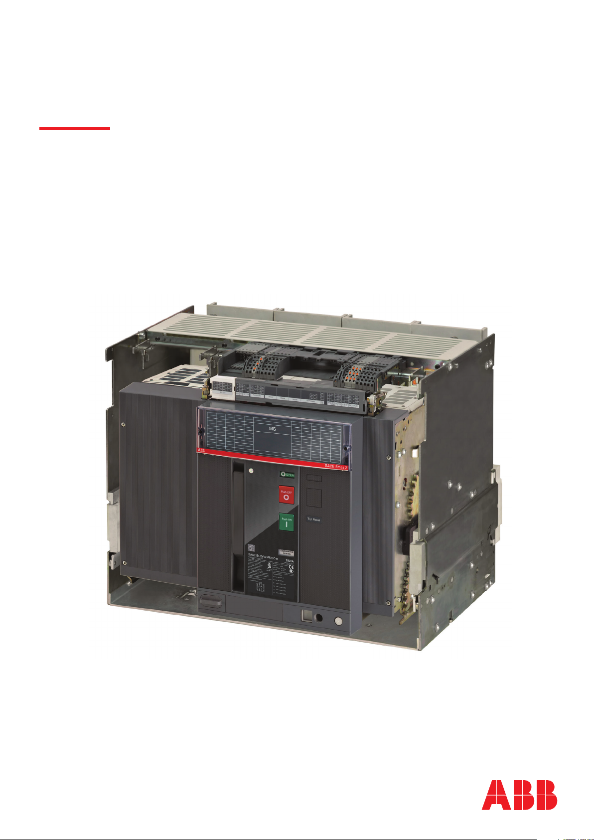
Front description................................................................. 15
Description of IEC+CCC specification data plate................ 16
Description of UL+IEC specification data plate................... 16
Description of UL+IEC+CCC specification data plate ......... 17
Manual operations for opening and closing the circuit-
breaker ............................................................................... 18
Mechanical status indicators .............................................. 19
Circuit breaker racking-in/racking-out operations ............... 20
Mechanical position indicators ........................................... 24
4 - Environmental conditions..............................................25
5 - Installation ....................................................................25
Warnings and precautions before the installation................ 25
Mounting of the fixed circuit-breaker .................................. 25
Mounting anti-insertion locks.............................................. 26
Mounting the fixed part of the withdrawable circuit-breaker 26
Types of terminal................................................................. 27
Change of position of the vertical/horizontal terminals ....... 28
Clearances.......................................................................... 28
Phase separators................................................................ 28
Connection to the power circuit.......................................... 28
Overall dimensions ............................................................. 30
Positioning anchor plates ................................................... 31
Grounding........................................................................... 32
Accessories ................................................................................ 33
1 - Overview.......................................................................33
Overview and connection.................................................... 33
2 - Wiring diagrams............................................................34
General wiring diagrams ..................................................... 34
Mechanical accessories...................................................... 37
Putting into service and maintenance....................................... 38
1 - Putting into service .......................................................38
Introduction ........................................................................ 38
General checks................................................................... 38
Check accessories.............................................................. 39
Final check list.................................................................... 41
2 - Identification of alarms or failures .................................42
Faults, causes and remedies............................................... 42
3 - Maintenance .................................................................44
Safety standards................................................................. 44
Skilled personnel ................................................................ 44
Circuit-breaker life .............................................................. 44
Maintenance schedule ........................................................ 45
4 - First level maintenance .................................................46
Preliminary operations ........................................................ 46
Inspections and general cleaning........................................ 46
Circuit-breaker connections and connections between circuit-
breaker and switchboard .................................................... 46
Disassembly operations...................................................... 47
Cleaning and lubrication of the operating mechanism ........ 48
Inspection of electrical and mechanical accessories........... 48
Final checks........................................................................ 49
Interlock check ................................................................... 49
5 - Second level maintenance ............................................50
Preliminary operations ........................................................ 50
Inspections and general cleaning........................................ 50
Circuit-breaker connections and connections between circuit-
breaker and switchboard .................................................... 51
Disassembly operations...................................................... 52
Cleaning and lubrication of the operating mechanism ........ 54
Inspection of electrical and mechanical accessories........... 55
Check for wear on the contacts .......................................... 56
Final checks........................................................................ 57
Interlock check ................................................................... 58
6 - Decommissioning and treatment at end of life ..............59
Safety standards................................................................. 59
Trained personnel ............................................................... 59
End of life treatment for circuit-breaker materials ............... 59
Disposal of packing materials ............................................. 59

II | © 2021 ABB SACE Emax 2 1SDH002083A1002 - ECN000119014 - Rev. A

ABB | SACE Emax 2
Glossary |3 | © 2021 ABB | 1SDH002083A1002 - ECN000119014 - Rev. A
Glossary
Term Description
SACE Emax 2 DC New series of ABB SACE air switch disconnectors
4P Disconnector configurations: four-pole (4P)

ABB | SACE Emax 2
4 | © 2021 ABB | 1SDH002083A1002 - ECN000119014 - Rev. A References | 1 - ABB documentation mentioned in this manual
References
1 - ABB documentation mentioned in this manual
Consult the following documents mentioned in this manual for further information about the topics covered:
Operating instructions for the design engineer
1SDH001330R1002
Technical catalog
1SDC200023D0906
Anti-insertion lock
1SDH001000R0701
Wiring diagrams
1SDM000017A1001
ABB Library Download Center
DownloADCenteR
Emax 2 Products
eMAx 2 PRoDuCtS

ABB | SACE Emax 2
Emax E4.2 circuit-breakers | 1 - Contents5 | © 2021 ABB | 1SDH002083A1002 - ECN000119014 - Rev. A
Emax E4.2 circuit-breakers
1 - Contents
Overview
This manual contains instructions on the operations to be performed on Emax E4.2 circuit-breakers
throughout their life cycle, from reception to installation, and from commissioning to subsequent maintenance
during operation, with particular attention to the environment at the end of the life cycle of the product.
Reception Installation Commissioning Maintenance Disposal
Figure 1
Integrated informations
The full description of the Emax 2 family is available in document 1SDH001330R1002 (Emax 2 engineering
manual) available on the website ABB library.
recipients
This manual refers to two user profiles, as defined by standard IEC 60050:
• Electrically Skilled Person (IEV 195-04-01): person with relevant education and experience to enable him
or her to perceive risks and to avoid hazards which electricity can create.
• Trained Persons in the electrical field (IEV 195-04-02): person adequately advised or supervised by electrically
skilled persons to enable him or her to perceive risks and to avoid danger which electricity can create.
IMPORTANT: This manual specifically indicates what operations can be performed
by people trained in the field of electricity. All the remaining operations described in
the handbook must be performed by skilled persons, in the electrical field. ABB
declines all liability for damage to persons or property caused by failure to comply
with the instructions in this document.
Specifications and supporting
documents
To ensure that the Emax 2 circuit-breaker is installed and configured correctly, please read the information in
this manual and in the technical documentation of the product, supplied with the circuit-breaker or available
in the website ABB liBRARy
Document Description
1SDC200023D0906 Sace Emax 2 CBs General catalog
1SDM000017A1001 Circuit diagrams of disconnectors Sace Emax 2 MS/DC-E
1SDC200013D0201 Technical catalog “SACE Emax 2 MS/DC-E”
Design notes
The information in this manual was written in Italian and then translated into other languages to conform to
the laws and/or commercial requirements concerning the product.

ABB | SACE Emax 2
6 | © 2021 ABB | 1SDH002083A1002 - ECN000119014 - Rev. A Emax E4.2 circuit-breakers | 2 - Safety
2 - Safety
Warnings
HAZARD
ACCIDENTAL CONTACT WITH LIVE
POINTS CAN CAUSE SHOCK, BURNS AND
RESULT IN DEATH.
Do not try to use the product in any way, before
having read this instruction manual
Figure 2
The following warnings must be respected:
• READ THE INSTRUCTION MANUAL CAREFULLY BEFORE ATTEMPTING TO INSTALL, OPERATE
OR REPAIR THE CIRCUIT-BREAKER/DISCONNECTOR.
• Store these instructions along with other documents for instruction, maintenance and installation, drawings
and descriptive notes on the circuit-breaker.
• Keep these documents available during the installation, operation and maintenance of the appliance. The
use of these instructions facilitates proper maintenance.
• Install the circuit-breaker within the limits of the project described in the instruction manual shipped with the
unit. These circuit-breakers are designed to operate with values of voltage and current within the limits of
plate ratings. Do not install this equipment in systems operating at nominal values exceeding these limits.
• Follow the safety procedures indicated by Your Company.
• Do not open any covers or doors, do not work on devices before removing power from all circuits, and
after making sure of that with a measuring instrument.
WARNING!
• detailed descriptions of standard procedures for installation, use, maintenance and principles for safe
operation are not included. It is important to note that this document contains safety and precaution
instructions, against certain methods (of installation, use and maintenance) that could cause harm to
personnel, damage devices, or make them unsafe.
• these warnings and alarms do not include all conceivable ways to make installation, use and maintenance
recommended by ABB or not, that may be made, or possible consequences and complications of each
conceivable way, nor shall ABB investigate all those ways.
• anyone using maintenance procedures or devices, recommended by ABB or not, must check thoroughly
that neither personal safety nor the safety devices are endangered by mode of installation, use, maintenance
or the instruments used. For more information, questions or specific problems contact your nearest ABB
representative.
• This manual is written for qualified personnel only and is not intended as a substitute for a proper course,
or experience about safety procedures for this device.
• for the products equipped with communication, the purchaser, the installer or the final customer is responsible
for applying all the IT safety measures necessary in order to prevent risks deriving from connection to
communication networks; such risks include, among other things, the use of the product by unauthorized
persons, alteration of its normal functionality, accessing and modifying the information.
• the purchaser, installer or end user is responsible for ensuring that notices and safety signs are posted and
that all access points and switching devices are locked securely when the switchgear is left unattended,
even momentarily.
• all the information contained in this document reflects the latest product information available at the time
of printing. We reserve the right to edit the document at any time and without notice

ABB | SACE Emax 2
Emax E4.2 circuit-breakers | 3 - Regulations7 | © 2021 ABB | 1SDH002083A1002 - ECN000119014 - Rev. A
3 - Regulations
Standards
Sace Emax 2 MS/DC-E series circuit-breakers conform to international standards:
• IEC 60947-3
• EN 60947-3
• UL 489F
• UL 489B
• GB/T 14048.3
They comply with the following EC directives:
• "Low Voltage Directive" (LVD) n° 2014/35/EU
• "Electromagnetic Compatibility Directive" (EMC) n° 2014/30/EU

ABB | SACE Emax 2
8 | © 2021 ABB | 1SDH002083A1002 - ECN000119014 - Rev. A Management operations | 1 - Transport and checking on receipt
Management operations
1 - Transport and checking on receipt
Introduction
In view of their weight, Sace Emax 2/MS 1500 V DC series switch disconnectors require particular care during
transport and handling.
They are distributed with following packages:
• one package for fixed circuit-breaker
• two packages for withdrawable circuit-breakers (one package for the fixed part and one for the mobile part).
WARNING! comply with the following instructions during each transport phase:
• The movable part of the circuit-breaker must be removed from the switchgear and/or
from the relative fixed part even if this latter is not installed in the switchgear.
• The circuit-breaker must be in the open position.
• The circuit-breaker must be protected and fastened in its original packing.
• The closing springs of the circuit-breaker must be completely discharged.
Weight of the circuit-breakers
with packaging
The following table specifies the weights of the circuit-breakers with packaging:
Standards Current Configuration Fixed 4p Withdrawable
4p Fixed part 4p
Kg Lbs Kg Lbs Kg Lbs
IEC 60947-3
4000A
4ps
120 265
80 176
97 214
3200A 120 265 97 214
2500A 105 231 81 179
2000A 105 231 81 179
1600A 105 231 81 179
4000A
2ps
114 252 90 198
3200A 114 252 90 198
2500A 104 229 79 174
2000A 104 229 79 174
1600A 104 229 79 174
UL 489B 3200A 4ps 132 (*) 292 (*) 108 (*) 238 (*)
2ps 140 (*) 308 (*) 115 (*) 254 (*)
UL 489B
UL 489F
2500A
4ps
132 (*) 292 (*) 108 (*) 238 (*)
2000A 119 262 94 207
1600A 119 262 94 207
2500A
2ps
140 (*) 308 (*) 115 (*) 254 (*)
2000A 115 253 88 194
1600A 115 253 88 194
(*) Terminals supplied not assembled
NOTE:
• the indicated weights refer to fixed circuit-breakers with rear terminals without accessories.
• the weights of the fixed part refer to the version with vertical rear terminals and, if present, with
jumpers.
Transport of the packaged
circuit-breaker
Consult the table "Weight of the circuit-breakers with packaging" before proceeding with the transport.
WARNING! Improper lifting can result in death, serious injury to persons and damage
to the equipment. Never lift a circuit-breaker and / or a fixed part above other people.
IMPORTANT: The trained personnel in charge of handling and lifting must use
appropriate safety equipment.

ABB | SACE Emax 2
Management operations | 1 - Transport and checking on receipt9 | © 2021 ABB | 1SDH002083A1002 - ECN000119014 - Rev. A
Identification of packaging
Examine the state of the packaging and check that:
• The data on the packaging plate match the data of the order.
• The box is intact and perfectly closed.
SACE EMAX E.24/MS 1500 V
VERSION
FIXED
POL4
TERMINALS
REAR HORIZONTAL TERMINALS
WITH ASSEMBLED ACCESSORIES
YO 24V AC-DC
CODE
A.B.
FB.N°
80156446401183
8031004035
Designed by ABB SACE Division
1SDA055987R1
1130055880 004100
BB44005099
1
2
4
5
3
6
Figure 3
Pos. Description
1Brief description of disconnector
2Description of accessories
3Commercial code
4Confirmation number and location
5Disconnector serial number
6Features of the circuit-breaker
Packaging checks
Examine the state of the material received and verify that:
• The circuit-breaker or the fixed part are consistent with the order.
• The circuit-breaker or the fixed part are completely intact.
IMPORTANT:
• If the material is to be stored, check it beforehand. For opening the packaging,
follow the procedures outlined in the section "Unpacking and handling - opening the
packages" on page 11
• In the case of any inconsistencies, report them within five days of reception. See the
paragraph "Damage and Discrepancy Report" in this chapter.
Damage and Discrepancy
Report
If there is any damage to the packaging upon receipt and / or inconsistencies between order and product
identification label or product please contact ABB. Damage to the packaging must be reported no later than
seven days from receipt of the material.
NOTE: The notification must indicate the Packing List number.

ABB | SACE Emax 2
10 | © 2021 ABB | 1SDH002083A1002 - ECN000119014 - Rev. A Management operations | 1 - Transport and checking on receipt
Storage method
Place the packaging (circuit-breakers and / or fixed parts) on a horizontal plane, not in contact with the floor.
If the circuit-breaker has been removed and reinserted in the package ensure, prior to storage that:
• The circuit-breaker is in the open position and the springs are discharged. See the chapter "Description
- circuit-breaker opening/closing operations" on page 18
• The circuit-breaker is protected and locked in its original packaging
WARNING! stack up to three packages of E4.2 circuit-breakers. If the package has
been opened, stacking is allowed as long as the package is re-wrapped as it was
originally.
Figure 4
OK! ≤3 NO!
Figure 5
WARNING! If the package with the terminals is joined to that of the circuit-breaker
(UL 2500A-3200A) additional packages cannot be stacked on top.
OK! NO!
Figure 6

ABB | SACE Emax 2
Management operations | 2 - Unpacking and handling11 | © 2021 ABB | 1SDH002083A1002 - ECN000119014 - Rev. A
2 - Unpacking and handling
Opening the packaging
NOTE: to unpack the circuit-breaker safely refer to the instruction sheet in the zipped packaging
pouch.
The following is the procedure for opening the packaging:
1. Cut the bands that wrap the packing box. See Figure 7 and Figure 8.
Figure 7 Figure 8
2. Open the upper part of the packing box. See Figure 9.
3. Remove the packing box by lifting it upwards. See Figure 10.
Figure 9 Figure 10
Continued on the next page

ABB | SACE Emax 2
12 | © 2021 ABB | 1SDH002083A1002 - ECN000119014 - Rev. A Management operations | 2 - Unpacking and handling
Continued from the previous page
4. Take out the screws (See Figure 11 Fixed circuit-breaker). Take out the screws and the mounting
brackets (See Figure 12 Moving part, Figure 13 Fixed part).
Figure 11 Fixed circuit-breaker Figure 12 Moving part
Figure 13 Fixed part
Disposal of packing materials
For disposal of the packaging materials see the chapter " 6 - Decommissioning and treatment at end of life
" on page 59.
Weight of circuit-breakers
without packaging
The following table specifies the weights of the circuit-breakers without packaging:
Standards Current Configuration Fixed 4p Withdrawable
4p Fixed part 4p
Kg Lbs Kg Lbs Kg Lbs
IEC 60947-3
4000A
4ps
110 243
80 176
87 192
3200A 110 243 87 192
2500A 95 209 71 157
2000A 95 209 71 157
1600A 95 209 71 157
4000A
2ps
104 230 80 176
3200A 104 230 80 176
2500A 94 207 69 152
2000A 94 207 69 152
1600A 94 207 69 152
Continued on the next page

ABB | SACE Emax 2
Management operations | 2 - Unpacking and handling13 | © 2021 ABB | 1SDH002083A1002 - ECN000119014 - Rev. A
Continued from the previous page
Standards Current Configuration Fixed 4p Withdrawable
4p Fixed part 4p
Kg Lbs Kg Lbs Kg Lbs
UL 489B 3200A 4ps 122 (*) 270 (*)
80 176
98 (*) 216 (*)
2ps 130 (*) 286 (*) 105 (*) 232 (*)
UL 489B
UL 489F
2500A
4ps
122 (*) 270 (*) 98 (*) 216 (*)
2000A 109 240 84 185
1600A 109 240 84 185
2500A
2ps
130 (*) 286 (*) 105 (*) 232 (*)
2000A 105 231 78 172
1600A 105 231 78 172
(*) Terminals supplied not assembled
NOTE:
• the indicated weights refer to fixed circuit-breakers with rear terminals without accessories.
• the weights of the fixed part refer to the version with vertical rear terminals and, if present, with
jumpers.
Lift the fixed circuit breaker
or the moving part of a
withdrawable circuit-breaker
WARNING! Improper lifting can result in death, serious injury to persons and damage
to the equipment. Never lift a circuit-breaker and / or a fixed part above other people.
IMPORTANT: The trained personnel in charge of handling and lifting must use
appropriate safety equipment.
To lift the circuit-breaker:
1. Raise the circuit-breaker from the base of the packaging with the aid of the lifting plates supplied with
the circuit-breaker. See Figure 14 and Figure 15.
Figure 14 Figure 15 Figure 16
To raise the fixed part of the circuit-breaker
1. Lift the fixed part from the base of the package using the purpose-made lifting points of the fixed part.
See Figure 16.
IMPORTANT: keep the lifting plates and manual until the disconnector is dismantled.

ABB | SACE Emax 2
14 | © 2021 ABB | 1SDH002083A1002 - ECN000119014 - Rev. A Management operations | 3 - Description
3 - Description
Description of switch
disconnector
Emax E4.2 circuit-breakers consist of a steel structure which houses the operating mechanism, the poles
and the auxiliary parts.
Each pole, insulated from the others, contains the breaking parts.
It is available in two types:
• fixed version
• withdrawable
The fixed version circuit-breaker has its own terminals for connection to the power circuit (Figure 17).
The withdrawable version consists of a movable part (Figure 18) and by a fixed part for connection to the
power circuit by its own terminals (Figure 19).
The moving and fixed parts are coupled together by special clamps installed on the movable part.
Figure 17 Figure 18
Figure 19

ABB | SACE Emax 2
Management operations | 3 - Description15 | © 2021 ABB | 1SDH002083A1002 - ECN000119014 - Rev. A
Front description
The following are the main components of the circuit-breaker:
1
2
3
4
8
7
6
5
Figure 20
Pos. Description
1Lever for manually charging the closing springs
2Name of the circuit-breaker
3CB open (O) / closed (I) indicator
4Opening pushbutton
5Mechanical signalling of tripped TU
6Closing pushbutton
7Springs charged-discharged signalling device
8Electrical data plate

ABB | SACE Emax 2
16 | © 2021 ABB | 1SDH002083A1002 - ECN000119014 - Rev. A Management operations | 3 - Description
Description of IEC+CCC
specification data plate
SACE
Accessories
S/N:
IEC-60947-3 GB/T 14048.3
Annex D
Ie=Ue=
Icw=
Ui=
Uimp=
Connection scheme
For admitted connection scheme see manuals
Admitted jumper kits:
YC
YU
YC2
YO
YO2
RTC
M
YR
AUX 4Q
AUX 6Q
0000000000000000
4000A
MADE IN ITALY
E4.2V MS/DC-E
DC-PV2
100kA (1s)
1500Vdc
12kV
4000A1500Vdc
DC-22A
1SDH002083A1
1SDA115473R1;
3A 400V AC
3A 400V AC
220V - 250V AC/DC
220V - 240V AC/DC
220V - 240V AC/DC
220V - 240V AC/DC
1SDA115474R1; 1SDA115475R1; 1SDA115476R1
LOAD
Configuration A
1
3
5
2
10
11
4
6
7
9
8
Figure 21
Pos. Description
1Type of circuit-breaker
2Rated current
3Circuit-breaker serial number
4Standards
5Rated service voltage
6Utilization category
7Admissible rated short-time current
8Impulse voltage
9Insulation voltage
10 Rated voltage of accessories
11 Circuit diagram (if present)
Description of UL+IEC
specification data plate
SACE
Accessories
S/N:
Ui= Uimp=
Connection scheme
YC
YU
YO
M
AUX 4Q
AUX 6Q
IEC-60947-3
Annex D
Ie=Ue=
Icw=
The MCS PV is suitable for use
on a circuit capable of delivering
not more than
maximun when protected by fuses
or CB with ampere rating not
exceeding MCS PV ampere rating
0000000000000000
3200A
MADE IN ITALY
E4.2V-A MS/DC-E
1500Vdc 12kV
3A 400V AC
3A 400V AC
220V - 250V AC/DC
220V - 240V AC/DC
220V - 240V AC/DC
220V - 240V AC/DC
3200A1500Vdc
DC-PV2DC-22A
100kA
PV-UL489B 1500Vdc E348799
100kA 1500Vdc
VPV M.C.S.
50°C
LOAD
Configuration D
1
3
5
12
4
6
2
5
9
11
10
7
8
6
Figure 22
Pos. Description
1Type of circuit-breaker
2Rated current
3Circuit-breaker serial number
4UL file number
5Standards
6Rated service voltage
7Utilization category
8Admissible rated short-time current
9Impulse voltage
10 Insulation voltage
11 Rated voltage of accessories
12 Circuit diagram

ABB | SACE Emax 2
Management operations | 3 - Description17 | © 2021 ABB | 1SDH002083A1002 - ECN000119014 - Rev. A
Description of UL+IEC+CCC
specification data plate
LOAD
Configuration B
SACE
Accessories
S/N:
Ui= Uimp=
Connection scheme
YC
YU
YO
M
AUX 4Q
AUX 6Q
IEC-60947-3
Annex D
Ie=Ue=
Icw=
The MCS PV is suitable for use
on a circuit capable of delivering
not more than
maximun when protected by fuses
or CB with ampere rating not
exceeding MCS PV ampere rating
Max Voltage
For
max rating, the BPS switch is suitable only
for use with battery power supply
Nominal voltage
short circuit current at nominal,
GB/T 14048.3
0000000000000000
2500A
MADE IN ITALY
E4.2V-A MS/DC-E
1500Vdc 12kV
3A 400V AC
3A 400V AC
220V - 250V AC/DC
220V - 240V AC/DC
220V - 240V AC/DC
220V - 240V AC/DC
2500A1500Vdc
DC-PV2DC-22A
100kA(1s)
PV-UL489B 1500Vdc E348799
100kA 1500Vdc
BPS-UL489F E501222 40°C
1250Vdc
PV M.C.S.
1500Vdc
100kA
1500Vdc
1250Vdc
BPS M.C.S.
50°C
1
12
3
2
9
11
5
10
7
8
6
5
4
6
Figure 23
Pos. Description
1Type of circuit-breaker
2Rated current
3Circuit-breaker serial number
4UL file number
5Standards
6Rated service voltage
7Utilization category
8Admissible rated short-time current
9Impulse voltage
10 Insulation voltage
11 Rated voltage of accessories
12 Circuit diagram

ABB | SACE Emax 2
18 | © 2021 ABB | 1SDH002083A1002 - ECN000119014 - Rev. A Management operations | 3 - Description
Manual operations for opening
and closing the circuit-breaker
The following is the sequence of steps for closing and opening the circuit-breaker:
1. Check that the circuit-breaker is open (open / closed indicator "O - OPEN"), and check that the springs
are discharged (spring signalling device "white - DISCHARGED SPRING") as indicated in Figure 24.
2. Charging the springs - Pull the lever [A] downwards several times until the springs charged signalling
device [B] is “yellow - CHARGED SPRING” as indicated in Figure 25.
Figure 24
A
B
Figure 25
3. Check that the circuit-breaker is open (open/closed signalling device “O - OPEN”), and check that the
springs are charged (springs signalling device “yellow - CHARGED SPRING”) as indicated in Figure 26.
4. Closing - Press the closing pushbutton “I - Push ON” as indicated in Figure 27.
Figure 26
Push ON
Figure 27
5. Check that the circuit-breaker is closed (open/closed indicator "I - CLOSED"), and check that the
springs are discharged (spring signalling device "white - DISCHARGED SPRING" as indicated in
Figure 28.
6. Opening - Press the opening pushbutton “O - Push OFF” as indicated in Figure 29.
Figure 28
Push OFF
Figure 29
Continued on the next page
Other manuals for SACE Emax 2
46
Table of contents
Other ABB Industrial Equipment manuals
Popular Industrial Equipment manuals by other brands

Wacker Neuson
Wacker Neuson RD 7 Series Operator's manual

SMC Networks
SMC Networks EX510 Series manual

APPLIED MATERIALS
APPLIED MATERIALS CoolEND 0190-13674 Installation, operation, basic service

ERICO
ERICO CADDY CPNAM Series instruction sheet

Schmalz
Schmalz VCMC-R QUICK operating instructions

Emerson
Emerson Rosemount 5900S Series Reference manual